Author Archives: ep

China factory World Harvester Part; Zkb65 Gearbox Gear I; Rice Combine Harvester Parts; Maxxi Harvester Part with Best Sales

Product Description

Product Description

Our Company is a professional agricultural machinery spare parts Maunfacturer in China.We focus on selling agricultural machinery and Spare parts.
  for example:Harvester 
 World harvester and spare parts :4LZ-4.0E;4LZ-5.0E;4LZ-6.0P
 
Kubota  harvester and spare parts                     :DC70;DC70G;DC60;DC95;DC105

Yanmar harvester and spare parts :AW72;AW85;YH1180

Zoomlion harvester and spare parts:4LZ=4.0ZD(PL50;PL60)

  for example:
    Tractos:LOVOL;YTO;WORLD ;KUBOTA
If you need it ,Please call me 


Detailed Photos


Product Parameters


Packaging & Shipping

Company Profile


FAQ

1.Q: How long is your delivery time?

A: Normally, it takes 15-20days to delivery after your deposit receipt or L/C at sight

2.How many spare parts can be loaded in 1 container?

1)20 Feet Container loads:15-18tons
2)40 High Cube Container loads:27tons
3)Sample or LCL shipment are also welcome

3.Q: What is the payment term?

A: Irrevocable L/C at sight or 30% T/T in advance and balance against B/L copy

Axle Spindle Types and Features

The axle spindle is an integral part of your vehicle’s suspension. There are several different types and features, including mounting methods, bearings, and functions. Read on for some basic information on axle spindles. The next part of the article will cover how to choose the correct axle spindle for your vehicle. This article will also discuss the different types of spindles available, including the differences between the rear and front bearings.
Driveshaft

Features

The improved axle spindle nut assembly is capable of providing additional performance benefits, including increased tire life and reduced seal failure. Its keyway features and radially inwardly extending teeth allow nut adjustment to be accomplished with precision. The invention further provides a unique, multi-piece locking mechanism that minimizes leakage and torque transfer. Its principles and features are detailed in the appended claims. For example, the improved axle spindle nut assembly is designed for use in vehicles that are equipped with a steering system.
The axle spindle nut assembly includes a nut 252 with threads 256 on its inner periphery. The axle spindle 50 also features threads 198 on its outer periphery. The nut is threaded onto the outboard end of the axle spindle 50 until it contacts the inboard surface of the axle spacer 26. In the assembled state, a bearing spacer 58 is also present on the axle spindle.
The axle spindle nut assembly can reduce axial end play between the wheel end assembly 52 and the axle spindle 50. It can be tightened to an extreme torque level, but if the thread faces separate, it will undercompress the bearing cone and spacer group. To minimize these disadvantages, the axle spindle nut assembly is a critical component of a wheel-end assembly. There are several types of axle spindle nuts.
The third embodiment of the axle spindle nut assembly 300 comprises an inner washer 202, an outer washer 310, and at least 1 screw 320. The axle spindle nut assembly 300 secures and preloads bearing cones 55, 57. Unlike the first embodiment, the axle spindle nut assembly 300 uses the inner washer 202, which is optional in the third embodiment. The inner washer 202 and outer washer 310 are similar to those of the first embodiment.

Functions

An axle spindle is 1 of the most important components of a vehicle’s suspension system. The spindle retains the position of bearings and a spacer in an axle by providing clamp force. The inner nut of an axle spindle should be properly torqued to ensure a secure fit. A spindle nut is also responsible for compressing bearings and spacers. If any of these components are missing, the spindle will not work properly.
An axle spindle is used in rear wheel drive cars. It carries the weight of the vehicle on the axle casing and transfers the torque from the differential to the wheels. The axle spindle and hub are secured on the spindle by large nuts. The axle spindle is a vital component of rear wheel drive vehicles. Hence, it is essential to understand the functions of axle spindle. These components are responsible for the smooth operation of a vehicle’s suspension system.
Axle spindles can be mounted in 3 ways: in the typical axle assembly, the spindles are bolted onto the ends of the tubular axle, and the axle is suspended by springs. Short stub-axle mounting uses a torsion beam that flexes to provide a smooth ride. A second washer is used to prevent excessive rotation of the axle spindle.
Apart from being a crucial component of the suspension system, the spindles of the wheels are responsible for guiding the vehicle in a straight line. They are connected to the steering axis and are used in different types of suspension systems. European cars use a MacPherson Strut suspension system in which the spindle is connected to the arms in the front and rear of the suspension frame. The MacPherson strut allows the shock absorber housing to turn the wheel.
Driveshaft

Methods of mounting

Various methods of mounting axle spindle are available. In general, these methods involve forming a tubular blank of uniform cross section and thickness, and receiving the bearing assembly against it. The spindle is then secured using a collar, which also serves as a bearing stop. In some cases, additional features are used to provide greater security. Some of these features may not be suitable for all applications. But they are generally suitable.
Axle spindle forming is usually done by progressive steps using hollow punches. The metallic body of the punch has an inner work surface, which receives the axle blank. A mandrel is fixed within the work opening of the punch. The punch body’s work surface forges the spindle about the mandrel. The punch has 2 ends, a closed and an open one.
A wheeled vehicle axle assembly (10) includes a cylindrical housing member (12 a) and a plurality of spindle mounting flanges (30) secured on the housing member. The spindles (16) are firmly attached to the housing member by means of coupling members. The coupling members are configured to distribute the bending loads imposed on the spindle by the axle. It is important to note that the coupling members can be either threaded or screwed.
Traditionally, axle spindles were made from tubular blanks of irregular thickness. This method allowed for a gradual reduction in diameter and eliminated the need for extra metal within the spindle. Similarly, axles made by cold forming eliminate the need for additional metal in the spindle. In this way, the overall cost of manufacture is also reduced. The material used for manufacturing axles also determines the size and shape of the final product.
Driveshaft

Bearings

A nut 16 is used to retain the wheel bearings on axle spindle 12. The nut comprises several parts. The first portion includes a plurality of threads and a deformable second portion. The nut may be disposed on the inboard or outboard end of the axle spindle. This type of nut is typically secured to the axle spindle by a retaining nut.
The bearings are installed in the spindle to allow the wheel hub to rotate. While bearings are greased, they can dry out over time. Consequently, you may hear a loud clicking sound when turning your vehicle. Alternatively, you may notice grease on the edges of your tires. Bearing failure can cause severe damage to your axle spindle. If you notice any of these symptoms, you may need to replace the bearings on your axle spindle. Fortunately, you can purchase the necessary bearing parts at O’Reilly Auto Parts.
There are 3 ways to mount an axle spindle. A typical axle assembly has the spindles bolted to the ends of the tubular axle. A torsion beam is also used to mount the spindles on the axle. This torsion beam acts like a spring to help make the ride smooth and bump-free. Lastly, the axle spindle is sometimes mounted as a bolt-on component.

Cost

If your axle spindle has been damaged, you may need to have it replaced. This part of the axle is relatively easy to replace, but you need to know how to do it correctly. To replace your axle spindle, you must first remove the damaged one. To do this, a technician will cut the weld. They will then thread the new 1 into the axle tube and torque it to specification. After that, they will weld the new axle spindle into place.
When you are thinking about the cost of an axle spindle replacement, you must first determine if it is worth it for your vehicle. It is generally a good idea to replace the spindle only if it is causing damage to your vehicle. You can also replace your axle housing if it is deteriorating. If you do not replace the spindle, you can risk damaging the axle housing. To save money, you can consider using a repair kit.
You can also purchase an axle nut socket set. Most wrenches have an adjusting socket for this purpose. The socket set should be suitable for most vehicle types. Axle spindle replacement costs around $500 to $600 before tax. However, you should be aware that these costs vary widely based on the type of vehicle you have. The parts can cost between $430 and $480, and the labor can cost anywhere from $50 to 70.

China factory World Harvester Part; Zkb65 Gearbox Gear I; Rice Combine Harvester Parts; Maxxi Harvester Part     with Best SalesChina factory World Harvester Part; Zkb65 Gearbox Gear I; Rice Combine Harvester Parts; Maxxi Harvester Part     with Best Sales

China Best Sales Agricultural Machinery Tractor Tie Rod End OEM 826852m91 907729m1 969352m1 135 240 250 Tractor Spare Parts near me factory

Product Description

Product Description

Warranty  1 Year Certification TS16949
Color Natural color Application Massey Ferguson
OEM NO. 826852M91  MOQ 100 PCS
Engravement Customized Port HangZhou/ZheJiang

Specifications

1.Supply to USA,Europe,and so on
2.Matrial:Body C45 Ball Pin Cr40
3.Professional Perfomance Auto parts supplier

Detail Images

Other Products

Our Company

Packing & Delivery

Certification

Our Service

1. OEM Manufacturing welcome: Product, Package…
2. Sample order
3. We will reply you for your inquiry in 24 hours.
4. after sending, we will track the products for you once every 2 days, until you get the products. When you got the
goods, test them, and give me a feedback.If you have any questions about the problem, contact with us, we will offer
the solve way for you.

FAQ

Q1. What is your terms of packing?
A: Generally, we pack our goods in neutral white boxes and brown cartons. If you have legally registered patent,
we can pack the goods in your branded boxes after getting your authorization letters.

Q2. What is your terms of payment?
A: T/T 30% as deposit, and 70% before delivery. We’ll show you the photos of the products and packages
before you pay the balance.

Q3. What is your terms of delivery?
A: EXW, FOB, CFR, CIF, DDU.

Q4. How about your delivery time?
A: Generally, it will take 30 to 60 days after receiving your advance payment. The specific delivery time depends
on the items and the quantity of your order.

Q5. Can you produce according to the samples?
A: Yes, we can produce by your samples or technical drawings. We can build the molds and fixtures.

Q6. What is your sample policy?
A: We can supply the sample if we have ready parts in stock, but the customers have to pay the sample cost and
the courier cost.

Q7. Do you test all your goods before delivery?
A: Yes, we have 100% test before delivery

Q8: How do you make our business long-term and good relationship?
A:1. We keep good quality and competitive price to ensure our customers benefit ;
2. We respect every customer as our friend and we sincerely do business and make friends with them,
no matter where they come from.

Axle Spindle Types and Features

The axle spindle is an integral part of your vehicle’s suspension. There are several different types and features, including mounting methods, bearings, and functions. Read on for some basic information on axle spindles. The next part of the article will cover how to choose the correct axle spindle for your vehicle. This article will also discuss the different types of spindles available, including the differences between the rear and front bearings.
Driveshaft

Features

The improved axle spindle nut assembly is capable of providing additional performance benefits, including increased tire life and reduced seal failure. Its keyway features and radially inwardly extending teeth allow nut adjustment to be accomplished with precision. The invention further provides a unique, multi-piece locking mechanism that minimizes leakage and torque transfer. Its principles and features are detailed in the appended claims. For example, the improved axle spindle nut assembly is designed for use in vehicles that are equipped with a steering system.
The axle spindle nut assembly includes a nut 252 with threads 256 on its inner periphery. The axle spindle 50 also features threads 198 on its outer periphery. The nut is threaded onto the outboard end of the axle spindle 50 until it contacts the inboard surface of the axle spacer 26. In the assembled state, a bearing spacer 58 is also present on the axle spindle.
The axle spindle nut assembly can reduce axial end play between the wheel end assembly 52 and the axle spindle 50. It can be tightened to an extreme torque level, but if the thread faces separate, it will undercompress the bearing cone and spacer group. To minimize these disadvantages, the axle spindle nut assembly is a critical component of a wheel-end assembly. There are several types of axle spindle nuts.
The third embodiment of the axle spindle nut assembly 300 comprises an inner washer 202, an outer washer 310, and at least 1 screw 320. The axle spindle nut assembly 300 secures and preloads bearing cones 55, 57. Unlike the first embodiment, the axle spindle nut assembly 300 uses the inner washer 202, which is optional in the third embodiment. The inner washer 202 and outer washer 310 are similar to those of the first embodiment.

Functions

An axle spindle is 1 of the most important components of a vehicle’s suspension system. The spindle retains the position of bearings and a spacer in an axle by providing clamp force. The inner nut of an axle spindle should be properly torqued to ensure a secure fit. A spindle nut is also responsible for compressing bearings and spacers. If any of these components are missing, the spindle will not work properly.
An axle spindle is used in rear wheel drive cars. It carries the weight of the vehicle on the axle casing and transfers the torque from the differential to the wheels. The axle spindle and hub are secured on the spindle by large nuts. The axle spindle is a vital component of rear wheel drive vehicles. Hence, it is essential to understand the functions of axle spindle. These components are responsible for the smooth operation of a vehicle’s suspension system.
Axle spindles can be mounted in 3 ways: in the typical axle assembly, the spindles are bolted onto the ends of the tubular axle, and the axle is suspended by springs. Short stub-axle mounting uses a torsion beam that flexes to provide a smooth ride. A second washer is used to prevent excessive rotation of the axle spindle.
Apart from being a crucial component of the suspension system, the spindles of the wheels are responsible for guiding the vehicle in a straight line. They are connected to the steering axis and are used in different types of suspension systems. European cars use a MacPherson Strut suspension system in which the spindle is connected to the arms in the front and rear of the suspension frame. The MacPherson strut allows the shock absorber housing to turn the wheel.
Driveshaft

Methods of mounting

Various methods of mounting axle spindle are available. In general, these methods involve forming a tubular blank of uniform cross section and thickness, and receiving the bearing assembly against it. The spindle is then secured using a collar, which also serves as a bearing stop. In some cases, additional features are used to provide greater security. Some of these features may not be suitable for all applications. But they are generally suitable.
Axle spindle forming is usually done by progressive steps using hollow punches. The metallic body of the punch has an inner work surface, which receives the axle blank. A mandrel is fixed within the work opening of the punch. The punch body’s work surface forges the spindle about the mandrel. The punch has 2 ends, a closed and an open one.
A wheeled vehicle axle assembly (10) includes a cylindrical housing member (12 a) and a plurality of spindle mounting flanges (30) secured on the housing member. The spindles (16) are firmly attached to the housing member by means of coupling members. The coupling members are configured to distribute the bending loads imposed on the spindle by the axle. It is important to note that the coupling members can be either threaded or screwed.
Traditionally, axle spindles were made from tubular blanks of irregular thickness. This method allowed for a gradual reduction in diameter and eliminated the need for extra metal within the spindle. Similarly, axles made by cold forming eliminate the need for additional metal in the spindle. In this way, the overall cost of manufacture is also reduced. The material used for manufacturing axles also determines the size and shape of the final product.
Driveshaft

Bearings

A nut 16 is used to retain the wheel bearings on axle spindle 12. The nut comprises several parts. The first portion includes a plurality of threads and a deformable second portion. The nut may be disposed on the inboard or outboard end of the axle spindle. This type of nut is typically secured to the axle spindle by a retaining nut.
The bearings are installed in the spindle to allow the wheel hub to rotate. While bearings are greased, they can dry out over time. Consequently, you may hear a loud clicking sound when turning your vehicle. Alternatively, you may notice grease on the edges of your tires. Bearing failure can cause severe damage to your axle spindle. If you notice any of these symptoms, you may need to replace the bearings on your axle spindle. Fortunately, you can purchase the necessary bearing parts at O’Reilly Auto Parts.
There are 3 ways to mount an axle spindle. A typical axle assembly has the spindles bolted to the ends of the tubular axle. A torsion beam is also used to mount the spindles on the axle. This torsion beam acts like a spring to help make the ride smooth and bump-free. Lastly, the axle spindle is sometimes mounted as a bolt-on component.

Cost

If your axle spindle has been damaged, you may need to have it replaced. This part of the axle is relatively easy to replace, but you need to know how to do it correctly. To replace your axle spindle, you must first remove the damaged one. To do this, a technician will cut the weld. They will then thread the new 1 into the axle tube and torque it to specification. After that, they will weld the new axle spindle into place.
When you are thinking about the cost of an axle spindle replacement, you must first determine if it is worth it for your vehicle. It is generally a good idea to replace the spindle only if it is causing damage to your vehicle. You can also replace your axle housing if it is deteriorating. If you do not replace the spindle, you can risk damaging the axle housing. To save money, you can consider using a repair kit.
You can also purchase an axle nut socket set. Most wrenches have an adjusting socket for this purpose. The socket set should be suitable for most vehicle types. Axle spindle replacement costs around $500 to $600 before tax. However, you should be aware that these costs vary widely based on the type of vehicle you have. The parts can cost between $430 and $480, and the labor can cost anywhere from $50 to 70.

China Best Sales Agricultural Machinery Tractor Tie Rod End OEM 826852m91 907729m1 969352m1 135 240 250 Tractor Spare Parts     near me factory China Best Sales Agricultural Machinery Tractor Tie Rod End OEM 826852m91 907729m1 969352m1 135 240 250 Tractor Spare Parts     near me factory

China high quality Gdk Part Number Jcb991/20023 Type Backhoe Loader near me shop

Product Description

GDK Part Number JCB991/2571 Type Backhoe Loader
Materiel: PTFE+NBR+PU+Ny

Special order: Require for other size or material, please contact us for further discussion about new CZPT and price.
Please send me 3 details about your engine application In order to give you fast and accurate pricing information.

  1. The Part Number
  2. The Centimeter Size
  3. Quantity

We set up the PTFE polymer materials, PU polyurethane and NBR materials seals producing line; Meanwhile, NOK, SKF, PARKER, CFW brand seals are also supplied well as the distributor in China.
All sealing products are widely used in different kinds of excavator and breaker hammer installation and maintenance systems, wining high reputation from the customers at home and abroad.
  

S/N CODE/ DESCRIPTION / SIZE
 
1 JCB 2002 NEW MODEL 550-41000 STABILIZER KIT
2 JCB 2002 NEW MODEL 550-41001 L.SHOVEL KIT
3 JCB 2002 NEW MODEL 550-41002 STEERING KIT
4 JCB 2002 NEW MODEL 550-41003 BUCKET KIT
5 JCB 2002 NEW MODEL 550-41004 SLEW KIT
6 JCB 2002 NEW MODEL 550-41008 LIFT KIT
7 JCB 2002 NEW MODEL 550-30444 DIPPER KIT
8 JCB 2002 NEW MODEL 550-4571 DIPPER KIT
9 JCB 2012 991-10142 SLEW KIT
10 JCB 2013 333/Y-6571 KIT
11 JCB 2013 333/Y-6571 DIPPER KIT
12 JCB 2013 333/Y-6571 BOOM KIT
13 JCB 2013 332/Y-8994 BUCKET KIT
14 JCB 2013 333/Y-9235 STEERING KIT
15 JCB 3DX 130-15110 STABILIZER KIT
16 JCB 3DX 130-15167 BOOM KIT
17 JCB 3DX 130-15089 STEERING KIT
18 JCB 3DX 130-15106 LIFT KIT
19 JCB 3DX 130-15107 BUCKET KIT
20 JCB 3DX 130-15168 DIPPER KIT
21 JCB 3DX 2003 550-42085 BOOM KIT
22 JCB 3DX 2003 550-42126 STABILIZER KIT
23 JCB 3DX 2003 550-42112 BUCKET KIT
24 JCB 3DX 2003 550-42098 DIPPER KIT
25 JCB 3DX NEW 2005 550-42854 BOOM KIT
26 JCB 3DX NEW 2005 550-42261 SLEW KIT
27 JCB 3DX NEW 2005 550-42383 STEERING KIT
28 JCB 3DX NEW 2005 550-42849 STABILIZER KIT
29 JCB 3DX NEW 2005 550-42835 L.SHOVEL KIT
30 JCB 3DX NEW 2005 550-42842 LIFT KIT
31 JCB 3DX NEW 2005 550-42855 BUCKET KIT
32 JCB 3DX NEW 2005 550-42847 DIPPER KIT
33 JCB 3DX 332/Y7633 SEAL KIT
34 JCB 4DX  550/42909 DIPPER KIT
35 JCB 4DX  550/35719 BOOM KIT
36 JCB 4DX  550/42904 STABILIZER KIT
37 JCB 4DX  550/41860 BUCKET KIT
38 JCB BLACK 2009 NEW MODEL  332/Y-5599 STABILIZER KIT
39 JCB BLACK 2009 NEW MODEL  332/Y-6192 DIPPER KIT
40 JCB BLACK 2009 NEW MODEL  332/Y-6440 BOOM KIT
41 JCB BLACK 2009 NEW MODEL  332/Y-6194 BOOM KIT
42 JCB BLACK 2009 NEW MODEL  332/Y-3519 STABILIZER KIT
43 JCB BLACK 2009 NEW MODEL  332/Y-3543 L.SHOVEL KIT
44 JCB BLACK 2009 NEW MODEL  332/Y-2186 LIFT KIT
45 JCB BLACK 2009 NEW MODEL  550/43774 LIFT KIT
46 JCB BLACK 2009 NEW MODEL  332/Y-6519 BUCKET KIT
47 JCB BLACK 2009 NEW MODEL  332/Y-6195 BUCKET KIT
48 JCB BLACK 2009 NEW MODEL  332/Y-6462 DIPPER KIT
       
49 L&T 770 SSP4216 Boom seal kit
50 L&T 770 SSP4217 Dipper seal kit
51 L&T 770 SSP4218 Seal kit
52 L&T 770 SSP4219 Seal kit
53 L&T 770 SSP4220 Lift seal kit
54 L&T 770 SSP4221 Tilt seal kit
55 L&T 770 SSP4222 Swing seal kit
56 L&T 770 SSP6889 Dipper seal kit
57 L&T 770 SSP6188 Swing seal kit
58 L&T 770 SSP6287 Stab seal kit
59 L&T 770 DC7310/650 Seal kit
60 L&T CASE DC7309/650 Boom seal kit
61 L&T CASE DC7305/650 Seal kit
62 L&T 770 DC7308/650 Dental seal kit
63 L&T 770 DC650/7454 Stab seal kit
64 L&T 770 DC650/7306 Bucket seal kit
65 L&T 770 DC650/7307 Lift seal kit
66 L&T 770 SSP7385 Tilt seal kit
67 TRX-760 SSP5095 Streering 
68 TRX-760 SSP5088 Dipper seal kit
69 TRX-760 SSP5092 L.BKT seal kit
70 TRX-760 SSP5093 Swing seal kit
71 TX760 SSP5087 Boom seal kit
72 TX760 SSP5089 Bucket seal kit
73 TEREX740 SSP8130 Seal kit
74 TEREX740 SSP8990 Seal kit
75 TEREX740 SSP7942 Dipper seal kit
76 TEREX SSP7214 Slew Seal Kit
77 L&T 770 DC650/7303 Lift seal kit
       
78 3CX JCB 991/00095 Repair seal kit
79 3CX JCB 991/00098 Repair seal kit
80 3CX JCB 991/00099 Repair seal kit
81 3CX JCB 991/5710 Repair seal kit
82 3CX JCB 991/5712 Repair seal kit
83 3CX JCB 991/5713 Repair seal kit
84 3CX JCB 991/00110 Repair seal kit
85 3CX JCB 991/00115 Repair seal kit
86 3CX JCB 991/00145 Repair seal kit
87 3CX JCB 991/00147 Repair seal kit
88 3CX JCB 991/00147P Repair seal kit
89 3CX JCB 991/00148 Repair seal kit
90 3CX JCB 991/00152 Repair seal kit
91 3CX JCB 991/00152P Repair seal kit
92 3CX JCB 991/00156 Repair seal kit
93 3CX JCB 991/10152 Repair seal kit
94 3CX JCB 991/20571 Repair seal kit
95 3CX JCB 991/20571 Repair seal kit
96 3CX JCB 991/2571 Repair seal kit
97 3CX JCB 991/20030 Repair seal kit
98 3CX JCB 991-00130 Repair seal kit
99 3CX JCB 991-00131 Repair seal kit
100 3CX JCB 991-00127 Repair seal kit
101 3CX JCB 991-00122 Repair seal kit
102 3CX JCB 991-00123 Repair seal kit
103 3CX JCB 991/00036 Repair seal kit
104 3CX JCB 991/20013 Repair seal kit

Agricultural Parts

Agricultural machinery, also known as agricultural machinery, is any mechanical device or structure used in agriculture . It includes hand tools, tractors and countless other farm implements. Agricultural machinery can be divided into 2 categories: power tools and hand tools. Some of the most common types of agricultural equipment are listed below. Each of these categories includes parts used to repair, maintain, and operate a specific piece of equipment or machinery. To learn more about agricultural machinery, please visit the Manufacturers and Suppliers section of our website.
agriculturalparts

Agricultural Machinery

Agricultural machinery parts are critical to the overall operation of a farm or ranch. Replacement parts are essential if your equipment is not functioning as expected. CZPT’s consumables experts are ready to help you find the right replacement parts for your equipment. You can rely on our knowledgeable staff to provide you with fast and accurate replacement services. If your agricultural machinery needs replacement parts, please contact us for assistance.
Key drivers of the agricultural machinery market include high global demand for food, rapid crop production, access to resources, and availability of credit. Agricultural machinery is mainly manufactured in Europe, the United States, Japan and China. Overall, we expect the agricultural machinery market to exceed $118 billion by 2025. Additionally, agricultural machinery OEM components are expected to grow at a CAGR of 3.6% over the next 5 years.
Agricultural machinery accessories include accessories and accessories other than tractor accessories. Plows loosen the soil and kill surface vegetation, fertilizer spreaders apply fertilizer evenly, rakes agitate the soil, and seeders sow seeds. Other accessories include balers, which collect materials and bundle them into management packs. Transplanters are used to transplant plants from 1 location to another. It must be properly maintained to maximize its useful life.
Farm machinery accessories can be found in all types of farming. From sowing to harvesting, farm machinery equipment is necessary to help farmers in various agricultural activities. Without mechanization, farming would not be as profitable as it is today. In Iran, Coulisse produces agricultural machinery parts including harrows, tillers, grain refiners, spinning machines and threshers. You can also find farm machinery accessories for sale through these companies.
A well-known brand in the field of agricultural machinery is New Holland. Parts can be found for New Holland and Case IH models. The company also produces replacement parts for many different models. The company’s extensive dealer network spans more than 160 countries. PDF also supplies agricultural machinery parts for brands such as Ford and New Holland. If you are looking for reliable quality and cost-effective agricultural machinery, we can get the parts you need from these brands.

Agricultural Equipment

Growing population and demand for equipment drive the demand for agricultural equipment in Asia. In countries with limited land such as India, low-paying agricultural jobs are not enough for many farmers. At the same time, Australia has a large amount of agricultural land, but the reduction of agricultural labor has led to the increasing mechanization and integration of agricultural production. This, in turn, has fueled a surge in demand for Australian agricultural products in Asia, particularly in China and India.
Tractor transplanter is a common agricultural equipment. Tractors pull on these machines, which dig holes and put plants into the holes. A cultivator is another type of agricultural equipment that tills the soil and controls weeds. Smaller operations often use a cultivator. Large plastic farms, on the other hand, need to invest in cladding, using a series of wheels to lay down a layer of plastic.
Agricultural machinery is widely used. For example, tractors can carry heavy agricultural attachments such as haymakers and grain turbines. Farm equipment also helps farmers prepare soil for growing and harvesting large quantities of crops. It also helps transport food to other regions for processing. These machines make farming easier and more efficient. With all these benefits, it’s no wonder so many people engage in farming as a profession. The world needs food and agriculture, and agricultural equipment is an integral part of the process.
Agricultural equipment operators use heavy agricultural machinery every day. They inspect the equipment and make minor repairs to keep it running smoothly. They also monitor the working environment and working conditions around the equipment. Depending on the field, agricultural equipment operators can operate a variety of agricultural equipment, load and unload products, and even harvest crops. These workers may spend most of the year working outdoors, which can take a long time. The average workweek for an agricultural equipment operator is approximately 18 hours.
Agricultural equipment operators often gain practical experience on the job. Some jobs in the industry may require a high school diploma, and students without a high school diploma can work on farms to learn the skills needed for the position. The industry requires employees to be properly trained and certified to operate equipment safely. AWS certification is highly recommended. All Associate of Applied Science in Agricultural Production Systems include core business and management courses applicable to the agricultural industry.
agriculturalparts

Agricultural machinery manufacturers

Agricultural machinery manufacturers produce agricultural implements such as tractors and combines for agricultural purposes. The production of these machines increases the productivity and efficiency of farmers around the world. These machines and parts increase the quality and quantity of crop production while reducing labor costs. They also help improve soil fertility. It’s important to choose the right type of machine for your farm because not all farm machinery is the same. There are many high-quality agricultural machinery manufacturers in China, whose prices are competitive with the local market prices.
The growth of the agricultural machinery market is mainly driven by the growing global food demand. Agricultural equipment manufacturers are investing in precision-based technologies, which allow them to build better agricultural machines. In addition, OEM parts manufacturers focus on the safety, quality and continuous improvement of agricultural machinery parts. With the shift in focus, the agricultural machinery market is expected to make great strides in the coming years. Along with these improvements, the demand for agricultural machinery OEM parts is expected to grow at an annual rate of over 3%.
Yuantong Group: This agricultural machinery manufacturer has more than 20 overseas service centers around the world. The company is committed to providing excellent customer service and provides a warranty on all of its products. Yuantong Machinery’s space parts are easily available at their service center. Shandong CZPT Heavy Industry International, a Chinese agricultural machinery manufacturer, was established in 1998 and is headquartered in Weifang City, Shandong Province.
Although the agricultural machinery industry is growing, the market is still affected by the economic downturn. The COVID-19 pandemic has put pressure on farming operations, who may forgo buying expensive equipment. Private investment in industrial equipment is also falling and is expected to decline further in 2020 and 2021. On the other hand, aftermarket agricultural machinery parts are tailored for an exact fit and outperform OEM parts.
agriculturalparts

Agricultural Machinery Suppliers

Agricultural Machinery Suppliers have a wide variety of products. From large farm machines to small ones, you’ll find it all in 1 place. In addition to providing first-class machinery, agricultural machinery suppliers can also provide you with spare parts. Shandong Heavy Industry International, for example, is China’s largest agricultural machinery maker, with annual sales of $9 billion. The company is headquartered in Weifang, Shandong and has been operating for more than 6 years.
Most farm equipment consists of hundreds of parts. For example, a typical tractor has more than 1,700 parts. Manufacturers have been shifting to just-in-time delivery of parts and raw materials. While the system works for predictable supply chains, it can break down when 1 component fails. Therefore, the best way to avoid problems and maximize profits is to get a list of Indian agricultural machinery suppliers through a dedicated marketplace.
Therefore, there are many suppliers of agricultural machinery. Some of the biggest names in the industry include CZPT and Caterpillar, both of which employ thousands of people. CZPT also offers a complete line of walk-behind and riding mowers, as well as log splitters and snow blowers. In addition, the German-made CZPT tractor line is being launched in Brazil. Finally, some smaller agricultural machinery enterprises produce and sell agricultural machinery.
In the next decade, the global agricultural machinery market will grow moderately. But in the short term, crop prices are expected to fall, which will negatively affect agricultural income and the agricultural machinery market. Experts predict that this will affect the demand for agricultural machinery. These factors will continue to influence the market and help farmers make better decisions. However, no single factor can guarantee that the agricultural machinery industry will not be affected by economic changes.
In addition to tractors, other types of agricultural machinery are also widely used for agricultural purposes. Tractors are the most common type of agricultural machinery and include rotary tillers, power tillers, subsoilers and trowels. Other equipment used for planting includes planters, planters and irrigation systems. Some specialized equipment includes sprinkler systems, micro sprinklers, and soil spray technology.

China high quality Gdk Part Number Jcb991/20023 Type Backhoe Loader     near me shop China high quality Gdk Part Number Jcb991/20023 Type Backhoe Loader     near me shop

China wholesaler 5h630-1072 Plate Valve CZPT Rice Combine Harvester Spare Parts near me manufacturer

Product Description

5H630-1072 Plate Valve CZPT Rice Combine Harvester Spare Parts
 

Welcome to Wubota

Product Details

Company Information

FAQs

How to Compare Different Types of Spur Gears

When comparing different types of spur gears, there are several important considerations to take into account. The main considerations include the following: Common applications, Pitch diameter, and Addendum circle. Here we will look at each of these factors in more detail. This article will help you understand what each type of spur gear can do for you. Whether you’re looking to power an electric motor or a construction machine, the right gear for the job will make the job easier and save you money in the long run.
Gear

Common applications

Among its many applications, a spur gear is widely used in airplanes, trains, and bicycles. It is also used in ball mills and crushers. Its high speed-low torque capabilities make it ideal for a variety of applications, including industrial machines. The following are some of the common uses for spur gears. Listed below are some of the most common types. While spur gears are generally quiet, they do have their limitations.
A spur gear transmission can be external or auxiliary. These units are supported by front and rear casings. They transmit drive to the accessory units, which in turn move the machine. The drive speed is typically between 5000 and 6000 rpm or 20,000 rpm for centrifugal breathers. For this reason, spur gears are typically used in large machinery. To learn more about spur gears, watch the following video.
The pitch diameter and diametral pitch of spur gears are important parameters. A diametral pitch, or ratio of teeth to pitch diameter, is important in determining the center distance between 2 spur gears. The center distance between 2 spur gears is calculated by adding the radius of each pitch circle. The addendum, or tooth profile, is the height by which a tooth projects above the pitch circle. Besides pitch, the center distance between 2 spur gears is measured in terms of the distance between their centers.
Another important feature of a spur gear is its low speed capability. It can produce great power even at low speeds. However, if noise control is not a priority, a helical gear is preferable. Helical gears, on the other hand, have teeth arranged in the opposite direction of the axis, making them quieter. However, when considering the noise level, a helical gear will work better in low-speed situations.

Construction

The construction of spur gear begins with the cutting of the gear blank. The gear blank is made of a pie-shaped billet and can vary in size, shape, and weight. The cutting process requires the use of dies to create the correct gear geometry. The gear blank is then fed slowly into the screw machine until it has the desired shape and size. A steel gear blank, called a spur gear billet, is used in the manufacturing process.
A spur gear consists of 2 parts: a centre bore and a pilot hole. The addendum is the circle that runs along the outermost points of a spur gear’s teeth. The root diameter is the diameter at the base of the tooth space. The plane tangent to the pitch surface is called the pressure angle. The total diameter of a spur gear is equal to the addendum plus the dedendum.
The pitch circle is a circle formed by a series of teeth and a diametrical division of each tooth. The pitch circle defines the distance between 2 meshed gears. The center distance is the distance between the gears. The pitch circle diameter is a crucial factor in determining center distances between 2 mating spur gears. The center distance is calculated by adding the radius of each gear’s pitch circle. The dedendum is the height of a tooth above the pitch circle.
Other considerations in the design process include the material used for construction, surface treatments, and number of teeth. In some cases, a standard off-the-shelf gear is the most appropriate choice. It will meet your application needs and be a cheaper alternative. The gear will not last for long if it is not lubricated properly. There are a number of different ways to lubricate a spur gear, including hydrodynamic journal bearings and self-contained gears.
Gear

Addendum circle

The pitch diameter and addendum circle are 2 important dimensions of a spur gear. These diameters are the overall diameter of the gear and the pitch circle is the circle centered around the root of the gear’s tooth spaces. The addendum factor is a function of the pitch circle and the addendum value, which is the radial distance between the top of the gear tooth and the pitch circle of the mating gear.
The pitch surface is the right-hand side of the pitch circle, while the root circle defines the space between the 2 gear tooth sides. The dedendum is the distance between the top of the gear tooth and the pitch circle, and the pitch diameter and addendum circle are the 2 radial distances between these 2 circles. The difference between the pitch surface and the addendum circle is known as the clearance.
The number of teeth in the spur gear must not be less than 16 when the pressure angle is 20 degrees. However, a gear with 16 teeth can still be used if its strength and contact ratio are within design limits. In addition, undercutting can be prevented by profile shifting and addendum modification. However, it is also possible to reduce the addendum length through the use of a positive correction. However, it is important to note that undercutting can happen in spur gears with a negative addendum circle.
Another important aspect of a spur gear is its meshing. Because of this, a standard spur gear will have a meshing reference circle called a Pitch Circle. The center distance, on the other hand, is the distance between the center shafts of the 2 gears. It is important to understand the basic terminology involved with the gear system before beginning a calculation. Despite this, it is essential to remember that it is possible to make a spur gear mesh using the same reference circle.

Pitch diameter

To determine the pitch diameter of a spur gear, the type of drive, the type of driver, and the type of driven machine should be specified. The proposed diametral pitch value is also defined. The smaller the pitch diameter, the less contact stress on the pinion and the longer the service life. Spur gears are made using simpler processes than other types of gears. The pitch diameter of a spur gear is important because it determines its pressure angle, the working depth, and the whole depth.
The ratio of the pitch diameter and the number of teeth is called the DIAMETRAL PITCH. The teeth are measured in the axial plane. The FILLET RADIUS is the curve that forms at the base of the gear tooth. The FULL DEPTH TEETH are the ones with the working depth equal to 2.000 divided by the normal diametral pitch. The hub diameter is the outside diameter of the hub. The hub projection is the distance the hub extends beyond the gear face.
A metric spur gear is typically specified with a Diametral Pitch. This is the number of teeth per inch of the pitch circle diameter. It is generally measured in inverse inches. The normal plane intersects the tooth surface at the point where the pitch is specified. In a helical gear, this line is perpendicular to the pitch cylinder. In addition, the pitch cylinder is normally normal to the helix on the outside.
The pitch diameter of a spur gear is typically specified in millimeters or inches. A keyway is a machined groove on the shaft that fits the key into the shaft’s keyway. In the normal plane, the pitch is specified in inches. Involute pitch, or diametral pitch, is the ratio of teeth per inch of diameter. While this may seem complicated, it’s an important measurement to understand the pitch of a spur gear.
gear

Material

The main advantage of a spur gear is its ability to reduce the bending stress at the tooth no matter the load. A typical spur gear has a face width of 20 mm and will fail when subjected to 3000 N. This is far more than the yield strength of the material. Here is a look at the material properties of a spur gear. Its strength depends on its material properties. To find out what spur gear material best suits your machine, follow the following steps.
The most common material used for spur gears is steel. There are different kinds of steel, including ductile iron and stainless steel. S45C steel is the most common steel and has a 0.45% carbon content. This type of steel is easily obtainable and is used for the production of helical, spur, and worm gears. Its corrosion resistance makes it a popular material for spur gears. Here are some advantages and disadvantages of steel.
A spur gear is made of metal, plastic, or a combination of these materials. The main advantage of metal spur gears is their strength to weight ratio. It is about 1 third lighter than steel and resists corrosion. While aluminum is more expensive than steel and stainless steel, it is also easier to machine. Its design makes it easy to customize for the application. Its versatility allows it to be used in virtually every application. So, if you have a specific need, you can easily find a spur gear that fits your needs.
The design of a spur gear greatly influences its performance. Therefore, it is vital to choose the right material and measure the exact dimensions. Apart from being important for performance, dimensional measurements are also important for quality and reliability. Hence, it is essential for professionals in the industry to be familiar with the terms used to describe the materials and parts of a gear. In addition to these, it is essential to have a good understanding of the material and the dimensional measurements of a gear to ensure that production and purchase orders are accurate.

China wholesaler 5h630-1072 Plate Valve CZPT Rice Combine Harvester Spare Parts     near me manufacturer China wholesaler 5h630-1072 Plate Valve CZPT Rice Combine Harvester Spare Parts     near me manufacturer

China Best Sales Speed Reducer Gearbox Tractor Parts for Agricultural Equipment with Free Design Custom

Product Description

Speed Reducer Gearbox Tractor Parts For Agricultural Equipment

Our helical agricultural gearbox has many items for your choosing and we can produce as per your drawing or sample to meet your special request
1. Large output torque
2. Safe, reliable, economical and durable
3. Stable transmission, quiet operation
4. High carrying ability
5. High modularization design, may equip with various outer power input conveniently. Same machine type may equip with various power motor. It is easy to realize the combination and junction between every machine type
6. Transmission ratio: Fine division, wide scope. The combined machine type may form very large transmission ratio, i. E. Output very low rotary speed.
7. Form of installation: The position to be installed is not limited.
8. High strength, compact the box body of high strength cast iron, gear and gear shaft adapts the gas carbonization, quenching and fine grinding process, therefore the bearing capacity of unit volume is high.
9. Long life: Under the condition of correct type chosen(including choosing suitable operation parament ) normal operation and maintenance, the life if main parts speed reducer(except wearing parts)should not be less than 20000 hours. The wearing parts include lubricating oil, oil seal and bearing.
10. Low noise: Because main parts of speed reducer are processed, and tested critically, therefore the noise of speed reducer is low.
11. Parallel axis-bevel wheel speed-down motor.
See the below features:
Size: 40mm—160mm
Reduction ratio: 3 — 512
Torque transmission: 5 Nm — 8 95 Nm
Precision backlash: ≤ 5arcmin
Running noise: 51 70 dB (A)
You are welcome to send us detail enquiry by e-mail or fax.
We can also supply Gearbox, agricultural gearbox, planetary gearbox, worm gearbox, flender gearbox, marine gearbox, gearbox, reduction gearbox, transmission gearbox, gearbox, mower gearbox, rotary cutter gearbox, small transmission gearbox, gearbox for conveyor, bevel gearbox, helical gearbox, swing gearbox, variable speed gearbox, differential gearbox, small planetary gearbox, reducer gearbox, tiller gearbox, pto gearbox, gearbox reducer, hollow shaft gearbox, speed reduction gearbox, industrial gearbox, planetary reduction gearbox, lawn mower gearbox, rotary tiller gearbox, gearbox transmission, worm reduction gearbox, aluminum gearbox, forklift gearbox, nmrv 075 worm gearbox, nmrv030 worm gearbox, shaft mounted gearbox, nmrv 050 worm gearbox, gearbox for agricultural machinery, power tiller gearbox, manual worm gearbox, spiral bevel gearbox, nmrv gearbox, worm wheel gearbox, reduce speed gearbox, industrial transmission gearbox, worm reducer gearbox, gearbox rpm reducer, helical gearbox reducer, wheel planetary gearbox, nmrv040 worm gearbox, worm gearbox reducer, nmrv worm gearbox, aluminium worm gearbox, gearbox reduction, rv series worm gearbox, worm speed gearbox, nmrv050 worm gearbox, gear reducer, worm gear reducer, helical gear reducer, gear speed reducer, worm gear speed reducer, shaft mounted gear reducer, planetary gear reducer, helical gear speed reducer, worm gear wheel reducer, speed gear reducer, bevel gear reducer, planetary gear speed reducer, spur gear reducer, aluminum worm gear reduce, nmrv worm gear reducers, helical-worm gear reducer, helical bevel gear reducers, high speed gear reducer, gear speed reducers, industrial gear reducer, high torque gear reducers

HangZhou CZPT Industry Co., Ltd. is a specialized supplier of a full range of chains, sprockets, gears, gear racks, v belt pulley, timing pulley, V-belts, couplings, machined parts and so on.

Due to our sincerity in offering best service to our clients, understanding of your needs and overriding sense of responsibility toward filling ordering requirements, we have obtained the trust of buyers worldwide. Having accumulated precious experience in cooperating with foreign customers, our products are selling well in the American, European, South American and Asian markets. Our products are manufactured by modern computerized machinery and equipment. Meanwhile, our products are manufactured according to high quality standards, and complying with the international advanced standard criteria.

With many years’ experience in this line, we will be trusted by our advantages in competitive price, one-time delivery, prompt response, on-hand engineering support and good after-sales services.

Additionally, all our production procedures are in compliance with ISO9001 standards. We also can design and make non-standard products to meet customers’ special requirements. Quality and credit are the bases that make a corporation alive. We will provide best services and high quality products with all sincerity. If you need any information or samples, please contact us and you will have our soon reply.

FAQ:
Q1: Are you trading company or manufacturer ?
A: We are factory.

Q2: How long is your delivery time and shipment?
1.Sample Lead-times: generally 10 workdays.
2.Production Lead-times: 20-40 workdays after getting your deposit.

Q3. What is your terms of payment?
A: T/T 30% as deposit, and 70% before delivery.

Q4: What is your advantages?
1. Manufacturer,the most competitive price and good quality.
2. Perfect technical engineers give you the best support.
3. OEM is available.
4. Rich stock and quick delivery.

Q5. If you can’t find the product on our website,what do you next?
Please send us inquiry with product pictures and drawings by email or other ways and we’ll check.


Spiral Gears for Right-Angle Right-Hand Drives

Spiral gears are used in mechanical systems to transmit torque. The bevel gear is a particular type of spiral gear. It is made up of 2 gears that mesh with 1 another. Both gears are connected by a bearing. The 2 gears must be in mesh alignment so that the negative thrust will push them together. If axial play occurs in the bearing, the mesh will have no backlash. Moreover, the design of the spiral gear is based on geometrical tooth forms.
Gear

Equations for spiral gear

The theory of divergence requires that the pitch cone radii of the pinion and gear be skewed in different directions. This is done by increasing the slope of the convex surface of the gear’s tooth and decreasing the slope of the concave surface of the pinion’s tooth. The pinion is a ring-shaped wheel with a central bore and a plurality of transverse axes that are offset from the axis of the spiral teeth.
Spiral bevel gears have a helical tooth flank. The spiral is consistent with the cutter curve. The spiral angle b is equal to the pitch cone’s genatrix element. The mean spiral angle bm is the angle between the genatrix element and the tooth flank. The equations in Table 2 are specific for the Spread Blade and Single Side gears from Gleason.
The tooth flank equation of a logarithmic spiral bevel gear is derived using the formation mechanism of the tooth flanks. The tangential contact force and the normal pressure angle of the logarithmic spiral bevel gear were found to be about 20 degrees and 35 degrees respectively. These 2 types of motion equations were used to solve the problems that arise in determining the transmission stationary. While the theory of logarithmic spiral bevel gear meshing is still in its infancy, it does provide a good starting point for understanding how it works.
This geometry has many different solutions. However, the main 2 are defined by the root angle of the gear and pinion and the diameter of the spiral gear. The latter is a difficult 1 to constrain. A 3D sketch of a bevel gear tooth is used as a reference. The radii of the tooth space profile are defined by end point constraints placed on the bottom corners of the tooth space. Then, the radii of the gear tooth are determined by the angle.
The cone distance Am of a spiral gear is also known as the tooth geometry. The cone distance should correlate with the various sections of the cutter path. The cone distance range Am must be able to correlate with the pressure angle of the flanks. The base radii of a bevel gear need not be defined, but this geometry should be considered if the bevel gear does not have a hypoid offset. When developing the tooth geometry of a spiral bevel gear, the first step is to convert the terminology to pinion instead of gear.
The normal system is more convenient for manufacturing helical gears. In addition, the helical gears must be the same helix angle. The opposite hand helical gears must mesh with each other. Likewise, the profile-shifted screw gears need more complex meshing. This gear pair can be manufactured in a similar way to a spur gear. Further, the calculations for the meshing of helical gears are presented in Table 7-1.
Gear

Design of spiral bevel gears

A proposed design of spiral bevel gears utilizes a function-to-form mapping method to determine the tooth surface geometry. This solid model is then tested with a surface deviation method to determine whether it is accurate. Compared to other right-angle gear types, spiral bevel gears are more efficient and compact. CZPT Gear Company gears comply with AGMA standards. A higher quality spiral bevel gear set achieves 99% efficiency.
A geometric meshing pair based on geometric elements is proposed and analyzed for spiral bevel gears. This approach can provide high contact strength and is insensitive to shaft angle misalignment. Geometric elements of spiral bevel gears are modeled and discussed. Contact patterns are investigated, as well as the effect of misalignment on the load capacity. In addition, a prototype of the design is fabricated and rolling tests are conducted to verify its accuracy.
The 3 basic elements of a spiral bevel gear are the pinion-gear pair, the input and output shafts, and the auxiliary flank. The input and output shafts are in torsion, the pinion-gear pair is in torsional rigidity, and the system elasticity is small. These factors make spiral bevel gears ideal for meshing impact. To improve meshing impact, a mathematical model is developed using the tool parameters and initial machine settings.
In recent years, several advances in manufacturing technology have been made to produce high-performance spiral bevel gears. Researchers such as Ding et al. optimized the machine settings and cutter blade profiles to eliminate tooth edge contact, and the result was an accurate and large spiral bevel gear. In fact, this process is still used today for the manufacturing of spiral bevel gears. If you are interested in this technology, you should read on!
The design of spiral bevel gears is complex and intricate, requiring the skills of expert machinists. Spiral bevel gears are the state of the art for transferring power from 1 system to another. Although spiral bevel gears were once difficult to manufacture, they are now common and widely used in many applications. In fact, spiral bevel gears are the gold standard for right-angle power transfer.While conventional bevel gear machinery can be used to manufacture spiral bevel gears, it is very complex to produce double bevel gears. The double spiral bevel gearset is not machinable with traditional bevel gear machinery. Consequently, novel manufacturing methods have been developed. An additive manufacturing method was used to create a prototype for a double spiral bevel gearset, and the manufacture of a multi-axis CNC machine center will follow.
Spiral bevel gears are critical components of helicopters and aerospace power plants. Their durability, endurance, and meshing performance are crucial for safety. Many researchers have turned to spiral bevel gears to address these issues. One challenge is to reduce noise, improve the transmission efficiency, and increase their endurance. For this reason, spiral bevel gears can be smaller in diameter than straight bevel gears. If you are interested in spiral bevel gears, check out this article.
Gear

Limitations to geometrically obtained tooth forms

The geometrically obtained tooth forms of a spiral gear can be calculated from a nonlinear programming problem. The tooth approach Z is the linear displacement error along the contact normal. It can be calculated using the formula given in Eq. (23) with a few additional parameters. However, the result is not accurate for small loads because the signal-to-noise ratio of the strain signal is small.
Geometrically obtained tooth forms can lead to line and point contact tooth forms. However, they have their limits when the tooth bodies invade the geometrically obtained tooth form. This is called interference of tooth profiles. While this limit can be overcome by several other methods, the geometrically obtained tooth forms are limited by the mesh and strength of the teeth. They can only be used when the meshing of the gear is adequate and the relative motion is sufficient.
During the tooth profile measurement, the relative position between the gear and the LTS will constantly change. The sensor mounting surface should be parallel to the rotational axis. The actual orientation of the sensor may differ from this ideal. This may be due to geometrical tolerances of the gear shaft support and the platform. However, this effect is minimal and is not a serious problem. So, it is possible to obtain the geometrically obtained tooth forms of spiral gear without undergoing expensive experimental procedures.
The measurement process of geometrically obtained tooth forms of a spiral gear is based on an ideal involute profile generated from the optical measurements of 1 end of the gear. This profile is assumed to be almost perfect based on the general orientation of the LTS and the rotation axis. There are small deviations in the pitch and yaw angles. Lower and upper bounds are determined as – 10 and -10 degrees respectively.
The tooth forms of a spiral gear are derived from replacement spur toothing. However, the tooth shape of a spiral gear is still subject to various limitations. In addition to the tooth shape, the pitch diameter also affects the angular backlash. The values of these 2 parameters vary for each gear in a mesh. They are related by the transmission ratio. Once this is understood, it is possible to create a gear with a corresponding tooth shape.
As the length and transverse base pitch of a spiral gear are the same, the helix angle of each profile is equal. This is crucial for engagement. An imperfect base pitch results in an uneven load sharing between the gear teeth, which leads to higher than nominal loads in some teeth. This leads to amplitude modulated vibrations and noise. In addition, the boundary point of the root fillet and involute could be reduced or eliminate contact before the tip diameter.

China Best Sales Speed Reducer Gearbox Tractor Parts for Agricultural Equipment     with Free Design CustomChina Best Sales Speed Reducer Gearbox Tractor Parts for Agricultural Equipment     with Free Design Custom

China Custom Precision Hydraulic Cylinder Cap Ductile Iron Casting Tractor Part/Metal Sand Machinery/Machined Steel /Mechanical/Motor/Casting/Cast/ Parts for Compressor Body near me shop

Product Description

Precision Hydraulic Cylinder Cap Ductile Iron Casting

Product description :


Item Name
 
Precision Hydraulic Cylinder Cap Ductile Iron Casting
 
 General Products      
 Application/Service Area
 
Metal Parts Solution for Vehicle, Agriculture machine, Construction Machine, transportation equipment, Valve and Pump system, Agriculture machine metal Parts, engine bracket, truck chassis bracket, gear box , gear housing , gear cover, shaft, spline shaft , pulley, flange, connection pipe, pipe, hydraulic valve , valve housing ,Fitting , flange, wheel, fly wheel, oil pump housing, starter housing, coolant pump housing, transmission shaft , transmission gear, sprocket, chains etc.
 
 Main blank Process for Casting  
Sand Casting , Resin Sand Casting, Green Sand Casting, Shell Molding, Automatic Molding, Lost Wax Casting, Lost Foam Molding Casting
 
 Blanks Tolerance -Casting  Tolerance CT9-10 for  Machine Molding Process,
CT8-9 for Shell Molding and Lost Foam Molding Casting Process
CT10-11 for Manual Molding Sand  casting Process
 Applicable Material  
See Table Below (Ductile Iron Casting, Grey Iron Casting)
OR According to customer requirement
 
 Casting Blank Size  /Dimensions 2 mm-2000mm / 0.08inch-79inch  for casting iron, according to customer requirement
 Casting Blank Weight Range from 0.01kg-1000kg for casting iron
 Applicable Machining Process  
CNC Machining/ Lathing/ Milling/ Turning/ Boring/ Drilling/ Tapping/ Broaching/Reaming /Grinding/Honing and  etc.
 
 Machining Tolerance From 0.005mm-0.01mm-0.1mm
 Machined Surface Quality Ra 0.8-Ra3.2, according to customer requirement
 Applicable Heat Treatment  
Normalization , annealing, quenching and tempering, Case Hardening, Nitriding, Carbon Nitriding, Induction Quenching
 
 Applicable Finish Surface  Treatment  
Shot/sand blast, polishing, Surface passivation, Primer Painting , Powder coating, ED- Coating, Chromate Plating, zinc-plate, Dacromat coating, Finish Painting.
 
 MOQ For iron casting : 100pcs
For Machining : 50pcs
 Lead Time 45days from the receipt date of deposit for ductile iron casting

Company Introduction :

ZheJiang CZPT International Trading Company is a trading company which is specialized in castings,

forgings and machinery parts.

Our products include all kinds of raw castings to be made of ductile iron , grey iron , brass , stainless

steel and aluminums, machined castings and forged parts . To make these parts according to the

customers’ drawings , we have relative suitable production craft and equipments, such as resin sand ,

sand CZPT , hot core boxes , lost-wax , lost  foam and so on .

Specially for hydrant bodies and valves’ bodies, we have collected rich experience for these products in

the past 16 year’s actual production, Now we are proud of our products with good surface and high quality

material. Whatever,we have been trying our best to provide our customers with better quality castings by

improving  production crafts and more careful quality control.

Looking Forward To Receiving Your Kind Favorable Reply At Your Earliest!
 

Types of Ball Bearings

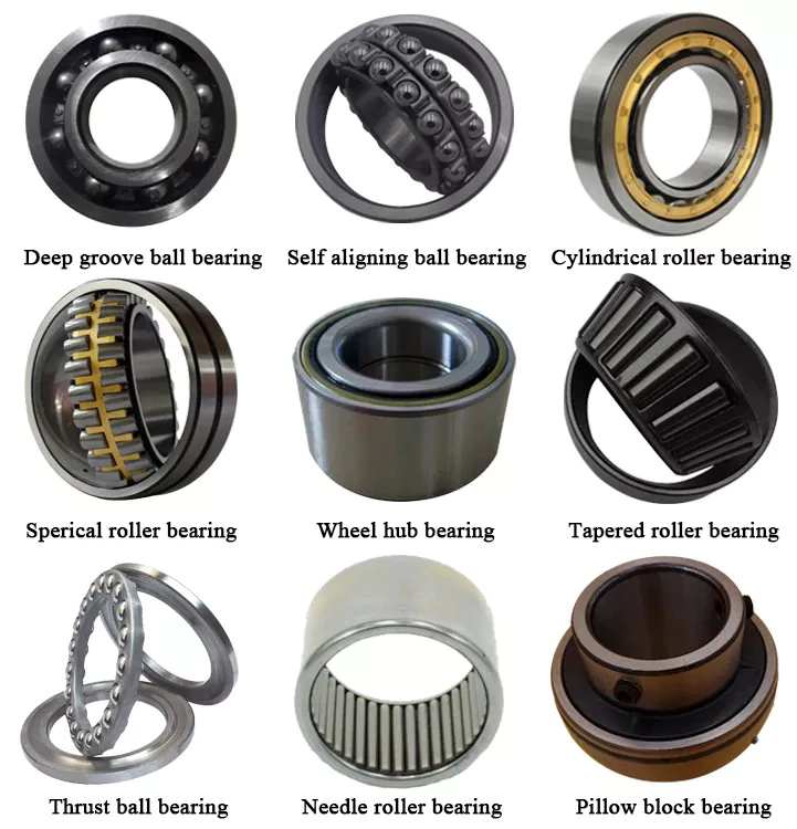
If you’re looking to purchase a new ball bearing, there are many different types available. Learn about Single-row designs, Ceramic hybrid bearings, and Self-aligning ball bearings. You can also choose from stainless steel or single-row designs. Then, read about the different types of materials available to you. You’ll have an easier time making a decision. After all, you won’t have to worry about maintaining your new ball bearing, since it will be maintained by your supplier.
bearing

Single-row designs

Ball bearings with a single-row design have a high load-carrying capacity. They are used in applications where high loads must be handled smoothly. A single-row design is a good choice when the material’s properties require high load-carrying capacity but limited axial load capability. Single-row designs use 2 bearings with similar design features, but they have different mounting methods. Single-row designs can be adjusted either against 1 another to accommodate axial loads.
The single-row design is suitable for high-speed applications, but also has some disadvantages. The contact angle a is the angle between the radial plane and contact line. The larger the angle, the higher the axial load carrying capacity of the bearing. Single-row angular contact ball bearings are suitable for higher axial forces. Single-row angular contact ball bearings have a single-row design and support high axial forces in 1 direction. Single-row ball bearings are available in both pressed steel and machined steel cages.
Angular contact ball bearings with a single row feature a cage made of fiber-glass reinforced polyamide 66. These are available in diameters up to 130 mm. Four-point angular contact ball bearings use brass, steel, or brass plate. They have good running properties and a low coefficient of linear expansion. Single-row designs are easy to mount and are widely available. Alternatively, they can be mounted with a universal match design, which allows them to be easily adjusted.
One-row angular contact ball bearings are generally not suitable for angular misalignments because they are unsuitable for compensation of angular misalignments. Misalignments cause internal forces in the bearing which reduce its radial load capacity and life expectancy. This type of bearing is not suitable for adjacent mounting as it increases the chances of misalignment. However, it is a suitable choice for applications where only 1 bearing is required per bearing position.

Ceramic hybrid bearings

While all-ceramic bearings are limited to very specialized applications, Si3N4-based hybrid bearings are finding use in a wide range of high-speed machines. Compared to steel, ceramics are less susceptible to centrifugal forces, which are directly proportional to the mass of the balls. Because Si3N4 replacement balls have a lower density than steel, these bearings reduce the stress placed on the outer race.
The benefits of hybrid bearings are clear: they allow for higher speeds and loads than full-ceramic bearings, and they require no lubrication. Because of their many benefits, many industrial equipment operators are switching to these innovative bearings. CBR is 1 company that specializes in ceramic hybrid bearings and can help you find the best product for your application. If you are thinking about purchasing ceramic bearings for your next machine, here are some things you need to know about them.
A ceramic ball bearing surface has an extremely low coefficient of friction, which is important for applications that require low friction and high speeds. Ceramic balls also have a higher hardness than steel balls, which increases their life. In addition to this, ceramic hybrid bearings have superior thermal properties, generating less heat even when spinning at high speeds. These properties make ceramic hybrid bearings an ideal choice for high-speed machinery, especially electric motors. They are also suitable for applications that operate under water.
A ceramic ball hybrid bearing is much less susceptible to temperature fluctuations and wear. Because they are essentially indestructible, ceramic balls do not generate wear particles from the adhesive wear. They can run at significantly higher speeds than steel balls. Ceramic balls are also more resistant to moisture. For this reason, grease is a recommended lubricant in most ceramic bearing applications. These lubricants offer superior protection against moisture and corrosion. Further, they are available in many types.
bearing

Self-aligning ball bearings

A self-aligning ball bearing is 1 type of self-aligning bearing. These bearings are recommended for use in flex shaft systems. Their self-aligning feature prevents them from misaligning when in use. They can be used in both single and multiple-joint systems. In addition to self-aligning ball bearings, these units also feature flex shafts.
These self-aligning ball bearings come in a variety of configurations, including cylindrical, round, tapered, and straight bore. Their inner ring is tapered to meet specific tolerances. They are suitable for operating temperatures ranging from -30°F to 120°F. Their wide range of applications allows them to be used in general machinery, precision instruments, and low noise motors. In addition, they are available in a variety of outside diameters, widths, and internal clearances.
Self-aligning ball bearings have 2 rows of balls and 1 common sphered raceway in the outer ring. This enables them to automatically compensate for angular misalignment, which may be caused by machining and assembly errors or deflections. Compared to spherical roller bearings, these self-aligning ball bearings generate less friction. They run cooler even at high speeds. Self-aligning ball bearings also offer free engineering support.
Self-aligning ball bearings are designed for difficult shaft alignment. They are double-row, self-retaining units, with cylindrical or tapered bores. These bearings are available in open and sealed designs, and can also be used in applications with misalignment. They are also available with an outer ring that rotates in relation to the inner ring. When it comes to shaft misalignment, self-aligning ball bearings are a great solution.

Stainless steel

Stainless steel is a metal that resists corrosion and is highly durable. Its corrosion-resistant and water-resistance properties make it a good choice for bearings in food and marine applications. Additionally, stainless steel has hygienic benefits. Here are some of the benefits of stainless steel ball bearings. Read on to learn more about these amazing bearings! We’ve included some of the most common uses for stainless steel.
Hardness is important in a ball bearing. Steel uses the Rockwell C scale to measure hardness. A grade 25 steel ball bearing is accurate to 25 millionths of an inch, while a grade 5 ceramic bearing is less than a half-inch round. Although roundness is important, it shouldn’t be overemphasized, as the bearing surfaces may not be as accurate as the grade of the metal. And remember, a higher price tag doesn’t mean a better product.
Stainless steel ball bearings are available in a variety of alloys. The alloys used in manufacturing a stainless steel ball bearing vary in hardness, strength, and ductility. Stainless steel ball bearings have high corrosion-resistance properties. Additionally, they have long lubrication lives. These benefits make them a popular choice for industrial applications. These bearings are easy to maintain, reduce replacement costs, and offer corrosion resistance.
The NTN Sentinel Series is a premium line of stainless steel bearings. The solid lube is NSF H1 registered and prevents grease from leaching into food. It is also corrosion-resistant and doesn’t need to be coated. The seals and slinger create a water-resistant barrier between the steel ball and the lubricant. It also adds safety and security to the bearing.
bearing

Plastic balls

For applications where noise and weight are major concerns, plastic balls are ideal. These non-magnetic balls are ideal for MRI X-ray machines and sensors. They are also easy to lubricate, and are non-magnetic. A polymer ball bearing is the lightest of all 3 types. This makes them a good choice for many industries. Read on to learn more. This article will introduce some of the advantages of plastic balls for ball bearings.
Although ceramic ball bearings are more durable and offer many advantages, they are more expensive than plastic. Fortunately, plastic ball bearings offer a cheaper alternative. These bearings feature all-plastic races and cages. Depending on the application, plastic balls can be used in applications involving chemicals. In these cases, plastic ball bearings are available with a C160 grade, which is safe for use in temperatures below 176 deg F.
Medical devices often require precision specialty balls, which are made of glass, stainless steel, and plastic. These bearings must meet stringent cleanliness requirements. To meet the most stringent requirements, they must undergo ultrasonic cleaning. These bearings are available in plastic raceways, and are also available with glass or stainless steel balls. Polyethylene balls are lightweight and can be used in a variety of applications. They can be ordered in different sizes and tolerances to meet specific requirements.
Plastic balls for ball bearings are often mounted into other parts, such as plastic wheels, pulleys, and housings. They can be seamlessly integrated into other parts of a machine, which reduces assembly time and improves affordability. One important advantage of plastic bearings is that they are rust-resistant. As such, they can be used in harsh environments without causing any damage. If a piece of equipment is exposed to extreme temperatures, polymers are the ideal choice.

China Custom Precision Hydraulic Cylinder Cap Ductile Iron Casting Tractor Part/Metal Sand Machinery/Machined Steel /Mechanical/Motor/Casting/Cast/ Parts for Compressor Body     near me shop China Custom Precision Hydraulic Cylinder Cap Ductile Iron Casting Tractor Part/Metal Sand Machinery/Machined Steel /Mechanical/Motor/Casting/Cast/ Parts for Compressor Body     near me shop

China Hot selling Good Quality CZPT CZPT Parts with Good quality

Product Description

good quality CZPT tractors parts

Product Description

1. Precision CNC machining parts strictly follow customers’ drawing, packing, and quality requirements.
2. Tolerance: between+/-0.01mm;
3. The high-tech CMM inspector to ensure the quality;
4. Full-Experienced engineers and well professional trained workers;
5. Fast delivery time;
6. Professional advice for our customers; 

Detailed Photos


Product Parameters

Our advantage of cnc machining:

Business Type Beyond the Manufacturer and strong organized ability in the industrial
Benefits 1. Deeper industrial experience at CNC machining parts service for more than 10-years,our customer’s requirement is our 1st priority.
2. 2D or 3D files is available;
3. We trust the quality priority and we insist the good quality should be based on the customers’ satisfied;
4. Without any MOQ requirement;
5.Faster delivery time;
6. Customized size and specification /OEM available
7. Near ZheJiang Port

The material

 
 Materials Accept
 
Stainless Steel SS201, SS303, SS304, SS316 etc.
Steel Q235, 20#, 45#,
Brass C36000 ( C26800), C37700 ( HPb59), C38500( HPb58), C27200(CuZn37) , C28000(CuZn40)
Iron 1213, 12L14,1215 etc.
Bronze C51000, C52100, C54400, etc.
Aluminum Al6061, Al6063,AL7075,AL5052 etc
Plastic ABS,POM,PC(Poly-Carbonate),PC+GF,PA(nylon),PA+GF,
PMMA(acrylic)PEEK,PEI etc)

Packaging & Shipping


  1. We prefer DHL or TNT express or other air freight between 1kg-100kg.
  2. we prefer sea freight more than 100kg or more than 1CBM
  3. As per customized specifications.


Company Profile

About us
HangZhou Emitech Technology Co.,Ltd is located in HangZhou City, ZheJiang  Province, Which closed the ZheJiang .The Emitech Technology is mainly engaged in the CNC Machinery Industrial Service for 15 years. Our Parts are sold to Europe, America, Japan, South Korea and China in various kinds of industrial.At present, Our company has CNC Turning machines and CNC centers and equip with professional quality and testing instruments.We have full OEM Experience from worldwide, providing them with One-stop solutions for a broad range of applications.We look forward to cooperating with you!


Our Advantages

1. Precision CNC machining parts strictly follow customer’s drawing,packing and quality requirement.
2. Tolerance: between+/-0.01mm;
3. The high-tech CMM inspector to ensure the quality;
4. Full-Experienced engineers and well professional trained workers;
5. Fast delivery time;
6. Professional advice for our customers; 

After Sales Service

china made industrial machine parts
We usually provide 12 Months repair service. If our duty, we will respond to send the new parts.

Our Service


Our Processing CNC center, CNC milling, CNC turning, drilling, grinding, bending, stamping, tapping,
Surface finish Polishing, sandblasting, Zinc-plated, nickel-plated, chrome-plated, silver-plated, gold-plated, imitation gold-plated,
Tolerance 0.05mm~0.1mm
QC System 100% inspection before shipment
Drawing format CAD / PDF/ DWG/ IGS/ STEP
Packaging Plastic bag/Standard package / Carton or Pallet / As per customized specifications
Payment Terms 30 -50%T/T in advance, 70-50% balance before delivery; Pay Pal or Western Union is acceptable.
Trade terms EXW, FOB, CIF, As per the customer’s request
Shipment Terms

1)We prefer DHL or TNT express or other air freight between 1kg-100kg.

2) we prefer sea freight more than 100kg or more than 1CBM
3) As per customized specifications.

Note The CNC machining parts are usually custom-made based on the customer’s drawings and samples. So we need the Down Payment


How to Replace the Drive Shaft

Several different functions in a vehicle are critical to its functioning, but the driveshaft is probably the part that needs to be understood the most. A damaged or damaged driveshaft can damage many other auto parts. This article will explain how this component works and some of the signs that it may need repair. This article is for the average person who wants to fix their car on their own but may not be familiar with mechanical repairs or even driveshaft mechanics. You can click the link below for more information.
air-compressor

Repair damaged driveshafts

If you own a car, you should know that the driveshaft is an integral part of the vehicle’s driveline. They ensure efficient transmission of power from the engine to the wheels and drive. However, if your driveshaft is damaged or cracked, your vehicle will not function properly. To keep your car safe and running at peak efficiency, you should have it repaired as soon as possible. Here are some simple steps to replace the drive shaft.
First, diagnose the cause of the drive shaft damage. If your car is making unusual noises, the driveshaft may be damaged. This is because worn bushings and bearings support the drive shaft. Therefore, the rotation of the drive shaft is affected. The noise will be squeaks, dings or rattles. Once the problem has been diagnosed, it is time to repair the damaged drive shaft.
Professionals can repair your driveshaft at relatively low cost. Costs vary depending on the type of drive shaft and its condition. Axle repairs can range from $300 to $1,000. Labor is usually only around $200. A simple repair can cost between $150 and $1700. You’ll save hundreds of dollars if you’re able to fix the problem yourself. You may need to spend a few more hours educating yourself about the problem before handing it over to a professional for proper diagnosis and repair.
The cost of repairing a damaged driveshaft varies by model and manufacturer. It can cost as much as $2,000 depending on parts and labor. While labor costs can vary, parts and labor are typically around $70. On average, a damaged driveshaft repair costs between $400 and $600. However, these parts can be more expensive than that. If you don’t want to spend money on unnecessarily expensive repairs, you may need to pay a little more.
air-compressor

Learn how drive shafts work

While a car engine may be 1 of the most complex components in your vehicle, the driveshaft has an equally important job. The driveshaft transmits the power of the engine to the wheels, turning the wheels and making the vehicle move. Driveshaft torque refers to the force associated with rotational motion. Drive shafts must be able to withstand extreme conditions or they may break. Driveshafts are not designed to bend, so understanding how they work is critical to the proper functioning of the vehicle.
The drive shaft includes many components. The CV connector is 1 of them. This is the last stop before the wheels spin. CV joints are also known as “doughnut” joints. The CV joint helps balance the load on the driveshaft, the final stop between the engine and the final drive assembly. Finally, the axle is a single rotating shaft that transmits power from the final drive assembly to the wheels.
Different types of drive shafts have different numbers of joints. They transmit torque from the engine to the wheels and must accommodate differences in length and angle. The drive shaft of a front-wheel drive vehicle usually includes a connecting shaft, an inner constant velocity joint and an outer fixed joint. They also have anti-lock system rings and torsional dampers to help them run smoothly. This guide will help you understand the basics of driveshafts and keep your car in good shape.
The CV joint is the heart of the driveshaft, it enables the wheels of the car to move at a constant speed. The connector also helps transmit power efficiently. You can learn more about CV joint driveshafts by looking at the top 3 driveshaft questions
The U-joint on the intermediate shaft may be worn or damaged. Small deviations in these joints can cause slight vibrations and wobble. Over time, these vibrations can wear out drivetrain components, including U-joints and differential seals. Additional wear on the center support bearing is also expected. If your driveshaft is leaking oil, the next step is to check your transmission.
The drive shaft is an important part of the car. They transmit power from the engine to the transmission. They also connect the axles and CV joints. When these components are in good condition, they transmit power to the wheels. If you find them loose or stuck, it can cause the vehicle to bounce. To ensure proper torque transfer, your car needs to stay on the road. While rough roads are normal, bumps and bumps are common.
air-compressor

Common signs of damaged driveshafts

If your vehicle vibrates heavily underneath, you may be dealing with a faulty propshaft. This issue limits your overall control of the vehicle and cannot be ignored. If you hear this noise frequently, the problem may be the cause and should be diagnosed as soon as possible. Here are some common symptoms of a damaged driveshaft. If you experience this noise while driving, you should have your vehicle inspected by a mechanic.
A clanging sound can also be 1 of the signs of a damaged driveshaft. A ding may be a sign of a faulty U-joint or center bearing. This can also be a symptom of worn center bearings. To keep your vehicle safe and functioning properly, it is best to have your driveshaft inspected by a certified mechanic. This can prevent serious damage to your car.
A worn drive shaft can cause difficulty turning, which can be a major safety issue. Fortunately, there are many ways to tell if your driveshaft needs service. The first thing you can do is check the u-joint itself. If it moves too much or too little in any direction, it probably means your driveshaft is faulty. Also, rust on the bearing cap seals may indicate a faulty drive shaft.
The next time your car rattles, it might be time for a mechanic to check it out. Whether your vehicle has a manual or automatic transmission, the driveshaft plays an important role in your vehicle’s performance. When 1 or both driveshafts fail, it can make the vehicle unsafe or impossible to drive. Therefore, you should have your car inspected by a mechanic as soon as possible to prevent further problems.
Your vehicle should also be regularly lubricated with grease and chain to prevent corrosion. This will prevent grease from escaping and causing dirt and grease to build up. Another common sign is a dirty driveshaft. Make sure your phone is free of debris and in good condition. Finally, make sure the driveshaft chain and cover are in place. In most cases, if you notice any of these common symptoms, your vehicle’s driveshaft should be replaced.
Other signs of a damaged driveshaft include uneven wheel rotation, difficulty turning the car, and increased drag when trying to turn. A worn U-joint also inhibits the ability of the steering wheel to turn, making it more difficult to turn. Another sign of a faulty driveshaft is the shuddering noise the car makes when accelerating. Vehicles with damaged driveshafts should be inspected as soon as possible to avoid costly repairs.

China Hot selling Good Quality CZPT CZPT Parts     with Good qualityChina Hot selling Good Quality CZPT CZPT Parts     with Good quality

China OEM High Quality Wholesale Custom Cheap 8-12mm 40cr Casting&Forging& Electrophoresis Backhoe Bucket Bush Excavator Spare Part wholesaler

Product Description

Quick Hitch Excavator Coupler Hydraulic Quick Hitch Excavator Quick Coupler

Product Description

Please confirm the size before placing the order

SINGLE FLANGE BUCKET BUSHING

SINGLE FLANGE BUCKET BUSHING

45*55*50

70*90*90

50*65*60

50*65*60

70*100*90

70*85*90

60*75*60

80*95*90

90*105*90

65*85*60

90*105*90

60*75*60

65*80*65

100*115*90

80*95*90

70*85*90

more

90*110*90


Application


How to Design a Forging Spur Gear

Before you start designing your own spur gear, you need to understand its main components. Among them are Forging, Keyway, Spline, Set screw and other types. Understanding the differences between these types of spur gears is essential for making an informed decision. To learn more, keep reading. Also, don’t hesitate to contact me for assistance! Listed below are some helpful tips and tricks to design a spur gear. Hopefully, they will help you design the spur gear of your dreams.
Gear

Forging spur gears

Forging spur gears is 1 of the most important processes of automotive transmission components. The manufacturing process is complex and involves several steps, such as blank spheroidizing, hot forging, annealing, phosphating, and saponification. The material used for spur gears is typically 20CrMnTi. The process is completed by applying a continuous through extrusion forming method with dies designed for the sizing band length L and Splitting angle thickness T.
The process of forging spur gears can also use polyacetal (POM), a strong plastic commonly used for the manufacture of gears. This material is easy to mold and shape, and after hardening, it is extremely stiff and abrasion resistant. A number of metals and alloys are used for spur gears, including forged steel, stainless steel, and aluminum. Listed below are the different types of materials used in gear manufacturing and their advantages and disadvantages.
A spur gear’s tooth size is measured in modules, or m. Each number represents the number of teeth in the gear. As the number of teeth increases, so does its size. In general, the higher the number of teeth, the larger the module is. A high module gear has a large pressure angle. It’s also important to remember that spur gears must have the same module as the gears they are used to drive.

Set screw spur gears

A modern industry cannot function without set screw spur gears. These gears are highly efficient and are widely used in a variety of applications. Their design involves the calculation of speed and torque, which are both critical factors. The MEP model, for instance, considers the changing rigidity of a tooth pair along its path. The results are used to determine the type of spur gear required. Listed below are some tips for choosing a spur gear:
Type A. This type of gear does not have a hub. The gear itself is flat with a small hole in the middle. Set screw gears are most commonly used for lightweight applications without loads. The metal thickness can range from 0.25 mm to 3 mm. Set screw gears are also used for large machines that need to be strong and durable. This article provides an introduction to the different types of spur gears and how they differ from 1 another.
Pin Hub. Pin hub spur gears use a set screw to secure the pin. These gears are often connected to a shaft by dowel, spring, or roll pins. The pin is drilled to the precise diameter to fit inside the gear, so that it does not come loose. Pin hub spur gears have high tolerances, as the hole is not large enough to completely grip the shaft. This type of gear is generally the most expensive of the three.
Gear

Keyway spur gears

In today’s modern industry, spur gear transmissions are widely used to transfer power. These types of transmissions provide excellent efficiency but can be susceptible to power losses. These losses must be estimated during the design process. A key component of this analysis is the calculation of the contact area (2b) of the gear pair. However, this value is not necessarily applicable to every spur gear. Here are some examples of how to calculate this area. (See Figure 2)
Spur gears are characterized by having teeth parallel to the shafts and axis, and a pitch line velocity of up to 25 m/s is considered high. In addition, they are more efficient than helical gears of the same size. Unlike helical gears, spur gears are generally considered positive gears. They are often used for applications in which noise control is not an issue. The symmetry of the spur gear makes them especially suitable for applications where a constant speed is required.
Besides using a helical spur gear for the transmission, the gear can also have a standard tooth shape. Unlike helical gears, spur gears with an involute tooth form have thick roots, which prevents wear from the teeth. These gears are easily made with conventional production tools. The involute shape is an ideal choice for small-scale production and is 1 of the most popular types of spur gears.

Spline spur gears

When considering the types of spur gears that are used, it’s important to note the differences between the two. A spur gear, also called an involute gear, generates torque and regulates speed. It’s most common in car engines, but is also used in everyday appliances. However, 1 of the most significant drawbacks of spur gears is their noise. Because spur gears mesh only 1 tooth at a time, they create a high amount of stress and noise, making them unsuitable for everyday use.
The contact stress distribution chart represents the flank area of each gear tooth and the distance in both the axial and profile direction. A high contact area is located toward the center of the gear, which is caused by the micro-geometry of the gear. A positive l value indicates that there is no misalignment of the spline teeth on the interface with the helix hand. The opposite is true for negative l values.
Using an upper bound technique, Abdul and Dean studied the forging of spur gear forms. They assumed that the tooth profile would be a straight line. They also examined the non-dimensional forging pressure of a spline. Spline spur gears are commonly used in motors, gearboxes, and drills. The strength of spur gears and splines is primarily dependent on their radii and tooth diameter.
SUS303 and SUS304 stainless steel spur gears

Stainless steel spur gears are manufactured using different techniques, which depend on the material and the application. The most common process used in manufacturing them is cutting. Other processes involve rolling, casting, and forging. In addition, plastic spur gears are produced by injection molding, depending on the quantity of production required. SUS303 and SUS304 stainless steel spur gears can be made using a variety of materials, including structural carbon steel S45C, gray cast iron FC200, nonferrous metal C3604, engineering plastic MC901, and stainless steel.
The differences between 304 and 303 stainless steel spur gears lie in their composition. The 2 types of stainless steel share a common design, but have varying chemical compositions. China and Japan use the letters SUS304 and SUS303, which refer to their varying degrees of composition. As with most types of stainless steel, the 2 different grades are made to be used in industrial applications, such as planetary gears and spur gears.
Gear

Stainless steel spur gears

There are several things to look for in a stainless steel spur gear, including the diametral pitch, the number of teeth per unit diameter, and the angular velocity of the teeth. All of these aspects are critical to the performance of a spur gear, and the proper dimensional measurements are essential to the design and functionality of a spur gear. Those in the industry should be familiar with the terms used to describe spur gear parts, both to ensure clarity in production and in purchase orders.
A spur gear is a type of precision cylindrical gear with parallel teeth arranged in a rim. It is used in various applications, such as outboard motors, winches, construction equipment, lawn and garden equipment, turbine drives, pumps, centrifuges, and a variety of other machines. A spur gear is typically made from stainless steel and has a high level of durability. It is the most commonly used type of gear.
Stainless steel spur gears can come in many different shapes and sizes. Stainless steel spur gears are generally made of SUS304 or SUS303 stainless steel, which are used for their higher machinability. These gears are then heat-treated with nitriding or tooth surface induction. Unlike conventional gears, which need tooth grinding after heat-treating, stainless steel spur gears have a low wear rate and high machinability.

China OEM High Quality Wholesale Custom Cheap 8-12mm 40cr Casting&Forging& Electrophoresis Backhoe Bucket Bush Excavator Spare Part     wholesaler China OEM High Quality Wholesale Custom Cheap 8-12mm 40cr Casting&Forging& Electrophoresis Backhoe Bucket Bush Excavator Spare Part     wholesaler

China Hot selling Rice Mill Spouting CZPT Spare Parts wholesaler

Product Description

We manufacturing – Prefabricated Chute Pipe + Diverter + Wind Net + Standard Parts

Low Speed Vertical Bucket Elevator Conveyor Food Grade Bucket Elevator for Rice
Rice mill plant Chain Conveyor and vertical bucket elevator


Low Speed SE Elevator Features:
SE series bucket elevator for rice has attacrtive and novel appearance, small sace requirement, large conveying capacity, low energy consumption, low rate of rice broken, less backflow characterisitcs. It is mainly applied in vertical lifiting for a variety of granular material in grain, oil, food and feed industries. Elevation to avoid broken.Auto-tightening on bucket belts.
 

Model Model

SE-6S

 SE-7S

 SE-8S

 SE – 10S

Capacity ( t / h )

 5-6

 9-11

 14-16

 25-30

Bucket belt linear speed (m/s)

 0.8~1.8

 0.8~1.8

 0.8~1.8

 0.8 ~ 1.8


TDTG High Speed Elevator Features:
TDTG series high speed elevator is a new generation product that researched and developed by digestion and absorption of foreign similar advanced technology. It is applicable to all kinds of granular and powder materials vertical conveying and can be widely used in CZPT and oil, flour, feed and chemical industries. 
 

Model Bucket Model Capacity (T/H) Linear Speed Height Model Bucket Model Capacity (T/H) Linear Speed Height

Link Chain Coveyor Features:
1.Suitable for all kinds of streamlined production of bulk and package ‘S logistics transportation.
2.With good stable performance safe dependability and easy operation.
3.Transportation capability is strong, transportation distance,
4.low energy consumption, and low cost of usage.
5. It is convenient to operate procedure control and automation, and also can go and down transportation.

Model Chain Distance Linear Speed Capacity (T/H) Conveying length

Factory Products Glance: 


The Mechanical Advantage of a Pulley

A pulley is an important tool for many tasks. The advantage that it offers over a hand-held mechanism is its mechanical advantage. In this article, we’ll discuss the types of pulleys and their applications. We’ll also look at the types of compound pulleys. And, of course, there’s a little bit about the mechanical advantage of a pulley. This article will help you decide whether this tool is right for your needs.
pulley

Mechanical advantage of a pulley

A pulley has a mechanical advantage over a lever because it is able to produce more force over longer distances. The mechanical advantage of a pulley sounds brilliant and could produce energy. But what exactly is this mechanical advantage? Let’s take a look. First, consider how a pulley works. A rope supports a 100kg mass, which requires 500 newtons of force to lift. If the rope supports a 100kg mass, 2 sections of rope can support that load. Using a pulley, you can lift the same weight with half the force.
A pulley’s ideal mechanical advantage is the ratio of the force applied to the total length of the rope. The larger the radius, the greater the mechanical advantage. A pulley made up of 4 rope segments has an ideal mechanical advantage of four. Therefore, a four-segment pulley would multiply the force applied by four. As the numbers on the rope segments are smaller than the total length of the rope, it would be better to use a compound pulley.
The mechanical advantage of a pulley can be calculated by using the T-method. The first step in calculating the mechanical advantage of a pulley is defining the force you need to lift. Then, divide that force by 2 to calculate the amount of force you need to lift the load. Once you know this amount, you can design a pulley to meet your needs. That way, you can achieve the perfect balance between the 2 types of pulleys.

Types of pulleys

The main function of the pulley is to change the direction of the force. The mechanical advantages of a single pulley are two. Ideally, 2 pulleys should have 2 or more mechanical advantages. The mechanical advantage of compound pulleys can be increased to 2 or more. The number of pulleys that make up the composite pulley will determine the mechanical advantage. Certain types of pulleys are combined in 1 housing.
A stepped pulley is a set of pulleys with stepped surfaces. Each face is anchored to the mid-axis in an ordered sequence. This design gives these pulleys their name. They are used to increase and decrease the speed of the driven pulley. Step pulleys are usually used in pairs. They can be straight or stepped, but usually come in pairs.
The 3 main types of pulleys are pulleys, rope pulleys, and chain pulleys. Pulley Pulley systems use mechanics to lift and lower heavy objects. The Greek historian Plutarch credits the invention of the pulley to Archimedes of ancient Sicily. The Mesopotamians used rope pulleys to lift water around 1500 BC, and Stonehenge is said to have been built using a rope pulley system.
pulley

Application of pulley system

The advantages of using a pulley system are numerous. The ability to lift heavy objects is a good example. The pulley system makes it easy for people to lift blocks and other large objects. It can be used in many different applications, from utility elevators to construction cranes. In addition, it is widely used on sailing boats. If you want to learn more about the benefits of a pulley system, keep reading!
You can use the pulley system to water flowers or water plants. Some of them even lowered the pot to make cleaning easier. Pendant lights are another great place to install a pulley system. Climbing and fishing are just some of the activities that utilize the pulley. They are great for fishing and gardening. And since they are so versatile, you can use the pulley system anywhere.
To get the most out of your pulley system, you must choose a product that has all of the above attributes. A high-quality pulley must have a large pulley diameter and be made of sturdy materials. The cables must also be properly supported in the pulleys to ensure a long service life for your investment. A good cable should have minimal cracks and be lubricated. These factors are the most important considerations when choosing a pulley system for your needs.

composite pulley

Composite pulley systems combine 2 or more movable pulleys. These systems maximize the force to move the weight and can also change direction so they can be used to lift weights. Composite pulley systems can be as simple or as complex as your needs. For example, a pulley pulley system uses multiple pulleys on each axis. This method is often used for hoisting building materials.
A compound pulley system has 2 or more rope segments, each of which is pulled up on a load. It can increase lift by making objects move faster. These systems are common on large sailboats and construction sites. Composite pulleys are also available for larger boats. Due to their versatility, they are versatile tools for construction sites and large sailboats. If you have their app, you should consider buying one.
The main advantage of composite pulleys is their versatility. You can use them to lift weights or use them to save energy. Composite pulleys are especially useful for lifting heavy objects. For example, you can tie a paper clip to the end of the rope and pull it up. The flag is then lifted into the air with the help of compound pulleys. Composite pulleys are a great invention and they are often used in construction.

security considerations

There are several safety considerations to consider when using pulleys. The first is Secure Workload (SWL). This value is a general guideline for the maximum weight a pulley can safely handle. It varies according to the height and angle of the pulley. Besides SWL, there are some other factors to consider. Consider each 1 before deciding on the pulley that best suits your needs.
Another safety consideration is the weight of the load. Since the highs of the pulley are higher than the lows, it doubles in weight. The weight of the high point should not exceed 4 kN. The safety factor is calculated by multiplying the strength of the pulley by the weight of the load. Secondary COD has a safety factor of 10:1 and bulletproof primary anchors should be used with pulleys.
If using a chain hoist, you must be trained in the appropriate type of lifting. It is important not to hang on the top hooks of the structure, nor to overload or rig the hooks with multiple slings. You should also avoid corroded or damaged chains, as they can cause the crane to jam or overload. A worn chain can even cause the load to drop.
pulley

Components of a pulley system

Proper design of the pulley system can increase the life of the cables and pulleys. Larger diameter cables should be selected as they are more durable than smaller diameter cables. The cables should also be supported in the pulley grooves. The pulley must be designed to be compatible with the cable and its lubrication should be optimal. Proper lubrication of cables and pulleys will ensure maximum durability and longevity.
The first type of pulley is called a fast pulley. These pulleys are used for quick start and stop of the machine. These pulleys are usually mounted in pairs on the countershaft of the machine. One pulley is tightly mounted on the machine shaft, while the other pulley is fitted with a free-spinning mechanism. When the machine is running, the belt is mounted on the tensioner pulley, and when it is stopped, the belt slides on the independent pulley.
Composite pulley sets reduce the overall effort required by reducing the size of the pulley. These are usually attributed to Archimedes. Flat pulleys are often used in flat belt driven transmission systems. These are used in high-speed, low-power applications. Flat pulley idlers are also used on the back of traditional V-belts.

China Hot selling Rice Mill Spouting CZPT Spare Parts     wholesaler China Hot selling Rice Mill Spouting CZPT Spare Parts     wholesaler

China manufacturer 654/704/754 Front Axle Flange Shaft Locking CZPT Tractor Parts with Great quality

Product Description

NEW HOLLAND TRACTOR PARTS 

RELATED PRODUCTS

KUBOTA TRACTOR PARTS :M6040,M7040,M9540,L3408,L4508,L3608,L4708

KUBOTA HARVESTER PARTS:PRO688,PRO758,PRO988,DC60,DC68G,DC70,
                                                    DC70PLUS,DC95,DC105

KUBOTA ENGINE PARTS:V2203,V2403,V2603,V3000,V3600,V3800,D1105,D782,D1803

KUBOTA  RICE TRANSPLANTER PARTS:SVP-6CMD,SPV-8CMD,NSPU-68CMD

PACKAING AND SHIPPING

OUR SERVICES

Product: We can provide high quality products with competitive price.

Production Capacity: we have good production capacity and we have enough spare parts stock and
can start to pack at once when you confirm your order.

Online Service: We will reply you at once when we get your enquiry, 24hours online service for you.
Welcome to contact us by email, ,viber,IMO

COMPANY INFORMATION 

Our Company is a professional agricultural machinery spare parts Manufacturer in China,
We specializes in agricultural machinery and accessories, we have a wealth of experience
in parts development, processing, production, so we are well aware of market demand and
can provide good products for our customers.We have been export to many countries such
as Southeast Asia, Australia, American, South America and Africa. We have enough parts
stock and can send out goods soon when customer place order. Dear Friends, it is our
pleasure to know you and look forward to your cooperation.We have a warehouse of 5000 square meters.


Why Checking the Drive Shaft is Important

If you hear clicking noises while driving, your driveshaft may need repair. An experienced mechanic can tell if the noise is coming from 1 side or both sides. This problem is usually related to the torque converter. Read on to learn why it’s so important to have your driveshaft inspected by an auto mechanic. Here are some symptoms to look for. Clicking noises can be caused by many different things. You should first check if the noise is coming from the front or the rear of the vehicle.
air-compressor

hollow drive shaft

Hollow driveshafts have many benefits. They are light and reduce the overall weight of the vehicle. The largest manufacturer of these components in the world is CZPT. They also offer lightweight solutions for various applications, such as high-performance axles. CZPT driveshafts are manufactured using state-of-the-art technology. They offer excellent quality at competitive prices.
The inner diameter of the hollow shaft reduces the magnitude of the internal forces, thereby reducing the amount of torque transmitted. Unlike solid shafts, hollow shafts are getting stronger. The material inside the hollow shaft is slightly lighter, which further reduces its weight and overall torque. However, this also increases its drag at high speeds. This means that in many applications hollow driveshafts are not as efficient as solid driveshafts.
A conventional hollow drive shaft consists of a first rod 14 and a second rod 14 on both sides. The first rod is connected with the second rod, and the second rod extends in the rotation direction. The 2 rods are then friction welded to the central area of ​​the hollow shaft. The frictional heat generated during the relative rotation helps to connect the 2 parts. Hollow drive shafts can be used in internal combustion engines and environmentally-friendly vehicles.
The main advantage of a hollow driveshaft is weight reduction. The splines of the hollow drive shaft can be designed to be smaller than the outside diameter of the hollow shaft, which can significantly reduce weight. Hollow shafts are also less likely to jam compared to solid shafts. Hollow driveshafts are expected to eventually occupy the world market for automotive driveshafts. Its advantages include fuel efficiency and greater flexibility compared to solid prop shafts.

Cardan shaft

Cardan shafts are a popular choice in industrial machinery. They are used to transmit power from 1 machine to another and are available in a variety of sizes and shapes. They are available in a variety of materials, including steel, copper, and aluminum. If you plan to install 1 of these shafts, it is important to know the different types of Cardan shafts available. To find the best option, browse the catalog.
Telescopic or “Cardan” prop shafts, also known as U-joints, are ideal for efficient torque transfer between the drive and output system. They are efficient, lightweight, and energy-efficient. They employ advanced methods, including finite element modeling (FEM), to ensure maximum performance, weight, and efficiency. Additionally, the Cardan shaft has an adjustable length for easy repositioning.
Another popular choice for driveshafts is the Cardan shaft, also known as a driveshaft. The purpose of the driveshaft is to transfer torque from the engine to the wheels. They are typically used in high-performance car engines. Some types are made of brass, iron, or steel and have unique surface designs. Cardan shafts are available in inclined and parallel configurations.
Single Cardan shafts are a common replacement for standard Cardan shafts, but if you are looking for dual Cardan shafts for your vehicle, you will want to choose the 1310 series. This type is great for lifted jeeps and requires a CV-compatible transfer case. Some even require axle spacers. The dual Cardan shafts are also designed for lifts, which means it’s a good choice for raising and lowering jeeps.
air-compressor

universal joint

Cardan joints are a good choice for drive shafts when operating at a constant speed. Their design allows a constant angular velocity ratio between the input and output shafts. Depending on the application, the recommended speed limit may vary depending on the operating angle, transmission power, and application. These recommendations must be based on pressure. The maximum permissible speed of the drive shaft is determined by determining the angular acceleration.
Because gimbal joints don’t require grease, they can last a long time but eventually fail. If they are poorly lubricated or dry, they can cause metal-to-metal contact. The same is true for U-joints that do not have oil filling capability. While they have a long lifespan, it can be difficult to spot warning signs that could indicate impending joint failure. To avoid this, check the drive shaft regularly.
U-joints should not exceed 70 percent of their lateral critical velocity. However, if this speed is exceeded, the part will experience unacceptable vibration, reducing its useful life. To determine the best U-joint for your application, please contact your universal joint supplier. Typically, lower speeds do not require balancing. In these cases, you should consider using a larger pitch diameter to reduce axial force.
To minimize the angular velocity and torque of the output shaft, the 2 joints must be in phase. Therefore, the output shaft angular displacement does not completely follow the input shaft. Instead, it will lead or lag. Figure 3 illustrates the angular velocity variation and peak displacement lead of the gimbal. The ratios are shown below. The correct torque for this application is 1360 in-Ibs.

Refurbished drive shaft

Refurbished driveshafts are a good choice for a number of reasons. They are cheaper than brand new alternatives and generally just as reliable. Driveshafts are essential to the function of any car, truck, or bus. These parts are made of hollow metal tubes. While this helps reduce weight and expense, it is vulnerable to external influences. If this happens, it may crack or bend. If the shaft suffers this type of damage, it can cause serious damage to the transmission.
A car’s driveshaft is a critical component that transmits torque from the engine to the wheels. A1 Drive Shaft is a global supplier of automotive driveshafts and related components. Their factory has the capability to refurbish and repair almost any make or model of driveshafts. Refurbished driveshafts are available for every make and model of vehicle. They can be found on the market for a variety of vehicles, including passenger cars, trucks, vans, and SUVs.
Unusual noises indicate that your driveshaft needs to be replaced. Worn U-joints and bushings can cause excessive vibration. These components cause wear on other parts of the drivetrain. If you notice any of these symptoms, please take your vehicle to the AAMCO Bay Area Center for a thorough inspection. If you suspect damage to the driveshaft, don’t wait another minute – it can be very dangerous.
air-compressor

The cost of replacing the drive shaft

The cost of replacing a driveshaft varies, but on average, this repair costs between $200 and $1,500. While this price may vary by vehicle, the cost of parts and labor is generally equal. If you do the repair yourself, you should know how much the parts and labor will cost before you start work. Some parts can be more expensive than others, so it’s a good idea to compare the cost of several locations before deciding where to go.
If you notice any of these symptoms, you should seek a repair shop immediately. If you are still not sure if the driveshaft is damaged, do not drive the car any distance until it is repaired. Symptoms to look for include lack of power, difficulty moving the car, squeaking, clanking, or vibrating when the vehicle is moving.
Parts used in drive shafts include center support bearings, slip joints, and U-joints. The price of the driveshaft varies by vehicle and may vary by model of the same year. Also, different types of driveshafts require different repair methods and are much more expensive. Overall, though, a driveshaft replacement costs between $300 and $1,300. The process may take about an hour, depending on the vehicle model.
Several factors can lead to the need to replace the drive shaft, including bearing corrosion, damaged seals, or other components. In some cases, the U-joint indicates that the drive shaft needs to be replaced. Even if the bearings and u-joints are in good condition, they will eventually break and require the replacement of the drive shaft. However, these parts are not cheap, and if a damaged driveshaft is a symptom of a bigger problem, you should take the time to replace the shaft.

China manufacturer 654/704/754 Front Axle Flange Shaft Locking CZPT Tractor Parts     with Great qualityChina manufacturer 654/704/754 Front Axle Flange Shaft Locking CZPT Tractor Parts     with Great quality