Author Archives: ep

Professional

The Different Types of Splines in a Splined Shaft

A splined shaft is a machine component with internal and external splines. The splines are formed in 4 different ways: Involute, Parallel, Serrated, and Ball. You can learn more about each type of spline in this article. When choosing a splined shaft, be sure to choose the right 1 for your application. Read on to learn about the different types of splines and how they affect the shaft’s performance.
splineshaft

Involute splines

Involute splines in a splined shaft are used to secure and extend mechanical assemblies. They are smooth, inwardly curving grooves that resist separation during operation. A shaft with involute splines is often longer than the shaft itself. This feature allows for more axial movement. This is beneficial for many applications, especially in a gearbox.
The involute spline is a shaped spline, similar to a parallel spline. It is angled and consists of teeth that create a spiral pattern that enables linear and rotatory motion. It is distinguished from other splines by the serrations on its flanks. It also has a flat top. It is a good option for couplers and other applications where angular movement is necessary.
Involute splines are also called involute teeth because of their shape. They are flat on the top and curved on the sides. These teeth can be either internal or external. As a result, involute splines provide greater surface contact, which helps reduce stress and fatigue. Regardless of the shape, involute splines are generally easy to machine and fit.
Involute splines are a type of splines that are used in splined shafts. These splines have different names, depending on their diameters. An example set of designations is for a 32-tooth male spline, a 2,500-tooth module, and a 30 degree pressure angle. An example of a female spline, a fillet root spline, is used to describe the diameter of the splined shaft.
The effective tooth thickness of splines is dependent on the number of keyways and the type of spline. Involute splines in splined shafts should be designed to engage 25 to 50 percent of the spline teeth during the coupling. Involute splines should be able to withstand the load without cracking.

Parallel splines

Parallel splines are formed on a splined shaft by putting 1 or more teeth into another. The male spline is positioned at the center of the female spline. The teeth of the male spline are also parallel to the shaft axis, but a common misalignment causes the splines to roll and tilt. This is common in many industrial applications, and there are a number of ways to improve the performance of splines.
Typically, parallel splines are used to reduce friction in a rotating part. The splines on a splined shaft are narrower on the end face than the interior, which makes them more prone to wear. This type of spline is used in a variety of industries, such as machinery, and it also allows for greater efficiency when transmitting torque.
Involute splines on a splined shaft are the most common. They have equally spaced teeth, and are therefore less likely to crack due to fatigue. They also tend to be easy to cut and fit. However, they are not the best type of spline. It is important to understand the difference between parallel and involute splines before deciding on which spline to use.
The difference between splined and involute splines is the size of the grooves. Involute splines are generally larger than parallel splines. These types of splines provide more torque to the gear teeth and reduce stress during operation. They are also more durable and have a longer life span. And because they are used on farm machinery, they are essential in this type of application.
splineshaft

Serrated splines

A Serrated Splined Shaft has several advantages. This type of shaft is highly adjustable. Its large number of teeth allows large torques, and its shorter tooth width allows for greater adjustment. These features make this type of shaft an ideal choice for applications where accuracy is critical. Listed below are some of the benefits of this type of shaft. These benefits are just a few of the advantages. Learn more about this type of shaft.
The process of hobbing is inexpensive and highly accurate. It is useful for external spline shafts, but is not suitable for internal splines. This type of process forms synchronized shapes on the shaft, reducing the manufacturing cycle and stabilizing the relative phase between spline and thread. It uses a grinding wheel to shape the shaft. CZPT Manufacturing has a large inventory of Serrated Splined Shafts.
The teeth of a Serrated Splined Shaft are designed to engage with the hub over the entire circumference of the shaft. The teeth of the shaft are spaced uniformly around the spline, creating a multiple-tooth point of contact over the entire length of the shaft. The results of these analyses are usually satisfactory. But there are some limitations. To begin with, the splines of the Serrated Splined Shaft should be chosen carefully. If the application requires large-scale analysis, it may be necessary to modify the design.
The splines of the Serrated Splined Shaft are also used for other purposes. They can be used to transmit torque to another device. They also act as an anti-rotational device and function as a linear guide. Both the design and the type of splines determine the function of the Splined Shaft. In the automobile industry, they are used in vehicles, aerospace, earth-moving machinery, and many other industries.

Ball splines

The invention relates to a ball-spinned shaft. The shaft comprises a plurality of balls that are arranged in a series and are operatively coupled to a load path section. The balls are capable of rolling endlessly along the path. This invention also relates to a ball bearing. Here, a ball bearing is 1 of the many types of gears. The following discussion describes the features of a ball bearing.
A ball-splined shaft assembly comprises a shaft with at least 1 ball-spline groove and a plurality of circumferential step grooves. The shaft is held in a first holding means that extends longitudinally and is rotatably held by a second holding means. Both the shaft and the first holding means are driven relative to 1 another by a first driving means. It is possible to manufacture a ball-splined shaft in a variety of ways.
A ball-splined shaft features a nut with recirculating balls. The ball-splined nut rides in these grooves to provide linear motion while preventing rotation. A splined shaft with a nut that has recirculating balls can also provide rotary motion. A ball splined shaft also has higher load capacities than a ball bushing. For these reasons, ball splines are an excellent choice for many applications.
In this invention, a pair of ball-spinned shafts are housed in a box under a carrier device 40. Each of the 2 shafts extends along a longitudinal line of arm 50. One end of each shaft is supported rotatably by a slide block 56. The slide block also has a support arm 58 that supports the center arm 50 in a cantilever fashion.
splineshaft

Sector no-go gage

A no-go gauge is a tool that checks the splined shaft for oversize. It is an effective way to determine the oversize condition of a splined shaft without removing the shaft. It measures external splines and serrations. The no-go gage is available in sizes ranging from 19mm to 130mm with a 25mm profile length.
The sector no-go gage has 2 groups of diametrally opposed teeth. The space between them is manufactured to a maximum space width and the tooth thickness must be within a predetermined tolerance. This gage would be out of tolerance if the splines were measured with a pin. The dimensions of this splined shaft can be found in the respective ANSI or DIN standards.
The go-no-go gage is useful for final inspection of thread pitch diameter. It is also useful for splined shafts and threaded nuts. The thread of a screw must match the contour of the go-no-go gage head to avoid a no-go condition. There is no substitute for a quality machine. It is an essential tool for any splined shaft and fastener manufacturer.
The NO-GO gage can detect changes in tooth thickness. It can be calibrated under ISO17025 standards and has many advantages over a non-go gage. It also gives a visual reference of the thickness of a splined shaft. When the teeth match, the shaft is considered ready for installation. It is a critical process. In some cases, it is impossible to determine the precise length of the shaft spline.
The 45-degree pressure angle is most commonly used for axles and torque-delivering members. This pressure angle is the most economical in terms of tool life, but the splines will not roll neatly like a 30 degree angle. The 45-degree spline is more likely to fall off larger than the other two. Oftentimes, it will also have a crowned look. The 37.5 degree pressure angle is a compromise between the other 2 pressure angles. It is often used when the splined shaft material is harder than usual.

Professional Professional

China manufacturer Adr 10-30V Truck Trailer Tractor LED Rear Turn Signal Lights LED Auto Light AAR Parts with Hot selling

Product Description

Product Description


  • * LED Truck Side Marker Light,LED Turning Light,LED Bus Indicator Light
    * High Quality with uv pc lens
    * E-mark ADR Approval

     * Manufacturer


  LTL1350A LTL1350R LTL1350W
Type LED Signal light, Tail  Light,Turn Lamp LED Signal light, Tail  Light,Stop Lamp LED Signal light, Tail  Light,Reverse Lamp
Car Made Trailer Truck  Car Trailer Truck  Car Trailer Truck  Car
Function LED Turn Light,  Marker Signal Light LED Stop Light, Marker Signal Light LED Reverse Light, Marker Signal Light
Production Name Turn Signal Light Stop Light Reverse Light 
Material UV PC + ABS UV PC + ABS UV PC+ABS
LED QTY 18 leds 18 leds 18 leds
Voltage 10-30 V 10-30 V  10-30 V
Power 13.5V 1.32W;  
28V 1.54W
13.5V R:1.68W P:0.22W 28V R:1.82W P:0.39W 13.5V 1.49W;  
28V 1.68W
Waterproof 100%Waterproof 100%Waterproof 100%Waterproof
Warranty 12Months 12Months 12Months
Certifications ADR ADR ADR


Packaging & Delivery


Packaging Details  pp bag + white box
Port HangZhou or ZheJiang port

Company Profile


Certifications

FAQ


Types of Miter Gears

The different types of miter gears include Hypoid, Crown, and Spiral. To learn more, read on. In addition, you’ll learn about their differences and similarities. This article will provide an overview of the different types of miter gears. You can also choose the type that fits your needs by using the guide below. After you’ve read it, you’ll know how to use them in your project. You’ll also learn how to pair them up by hand, which is particularly useful if you’re working on a mechanical component.
gear

Bevel gears

Bevel and miter gears are both used to connect 2 shafts that have different axes. In most cases, these gears are used at right angles. The pitch cone of a bevel gear has the same shape as that of a spur gear, except the tooth profile is slightly tapered and has variable depth. The pinions of a bevel gear are normally straight, but can be curved or skew-shaped. They can also have an offset crown wheel with straight teeth relative to the axis.
In addition to their industrial applications, miter gears are found in agriculture, bottling, printing, and various industrial sectors. They are used in coal mining, oil exploration, and chemical processes. They are an important part of conveyors, elevators, kilns, and more. In fact, miter gears are often used in machine tools, like forklifts and jigsaws.
When considering which gear is right for a certain application, you’ll need to think about the application and the design goals. For example, you’ll want to know the maximum load that the gear can carry. You can use computer simulation programs to determine the exact torque required for a specific application. Miter gears are bevel gears that are geared on a single axis, not two.
To calculate the torque required for a particular application, you’ll need to know the MA of each bevel gear. Fortunately, you can now do so with CZPT. With the help of this software, you can generate 3D models of spiral bevel gears. Once you’ve created your model, you can then machine it. This can make your job much easier! And it’s fun!
In terms of manufacturing, straight bevel gears are the easiest to produce. The earliest method for this type of gear is a planer with an indexing head. Since the development of CNC machining, however, more effective manufacturing methods have been developed. These include CZPT, Revacycle, and Coniflex systems. The CZPT uses the Revacycle system. You can also use a CNC mill to manufacture spiral bevel gears.
gear

Hypoid bevel gears

When it comes to designing hypoid bevel gears for miter and other kinds of gears, there are several important parameters to consider. In order to produce high-quality gearings, the mounting distance between the gear teeth and the pinion must be within a predefined tolerance range. In other words, the mounting distance between the gear teeth and pinion must be 0.05 mm or less.
To make this possible, the hypoid bevel gearset mesh is designed to involve sliding action. The result is a quiet transmission. It also means that higher speeds are possible without increasing noise levels. In comparison, bevel gears tend to be noisy at high speeds. For these reasons, the hypoid gearset is the most efficient way to build miter gears. However, it’s important to keep in mind that hypoid gears are not for every application.
Hypoid bevel gears are analogous to spiral bevels, but they don’t have intersecting axes. Because of this, they can produce larger pinions with smooth engagement. Crown bevel gears, on the other hand, have a 90-degree pitch and parallel teeth. Their geometry and pitch is unique, and they have particular geometrical properties. There are different ways to express pitch. The diametral pitch is the number of teeth, while circumferential measurement is called the circumference.
The face-milling method is another technique used for the manufacture of hypoid and spiral bevel gears. Face-milling allows gears to be ground for high accuracy and surface finish. It also allows for the elimination of heat treatment and facilitates the creation of predesigned ease-off topographies. Face-milling increases mechanical resistance by as much as 20%. It also reduces noise levels.
The ANSI/AGMA/ISO standards for geometric dimensioning differ from the best practices for manufacturing hypoid and bevel gears. The violation of common datum surfaces leads to a number of geometrical dimensioning issues. Moreover, hypoid gears need to be designed to incorporate the base pitches of the mating pinion and the hypoid bevel gear. This is not possible without knowing the base pitch of the gear and the mating pinion.

Crown bevel gears

When choosing crown bevels for a miter gear, you will need to consider a number of factors. Specifically, you will need to know the ratio of the tooth load to the bevel gear pitch radius. This will help you choose a bevel gear that possesses the right amount of excitation and load capacity. Crown bevels are also known as helical gears, which are a combination of 2 bevel gear types.
These bevel gears differ from spiral bevels because the bevels are not intersected. This gives you the flexibility of using a larger pinion and smoother engagement. Crown bevel gears are also named for their different tooth portions: the toe, or the part of the gear closest to the bore, and the heel, or the outermost diameter. The tooth height is smaller at the toe than it is at the heel, but the height of the gear is the same at both places.
Crown bevel gears are cylindrical, with teeth that are angled at an angle. They have a 1:1 gear ratio and are used for miter gears and spur gears. Crown bevel gears have a tooth profile that is the same as spur gears but is slightly narrower at the tip, giving them superior quietness. Crown bevel gears for miter gears can be made with an offset pinion.
There are many other options available when choosing a Crown bevel gear for miter gears. The material used for the gears can vary from plastics to pre-hardened alloys. If you are concerned with the material’s strength, you can choose a pre-hardened alloy with a 32-35 Rc hardness. This alloy also has the advantage of being more durable than plastic. In addition to being stronger, crown bevel gears are also easier to lubricate.
Crown bevel gears for miter gears are similar to spiral bevels. However, they have a hyperbolic, not conical, pitch surface. The pinion is often offset above or below the center of the gear, which allows for a larger diameter. Crown bevel gears for miter gears are typically larger than hypoid gears. The hypoid gear is commonly used in automobile rear axles. They are useful when the angle of rotation is 90 degrees. And they can be used for 1:1 ratios.
gear

Spiral miter gears

Spiral bevel gears are produced by machining the face surface of the teeth. The process follows the Hertz theory of elastic contact, where the dislocations are equivalent to small significant dimensions of the contact area and the relative radii of curvature. This method assumes that the surfaces are parallel and that the strains are small. Moreover, it can reduce noise. This makes spiral bevel gears an ideal choice for high-speed applications.
The precision machining of CZPT spiral miter gears reduces backlash. They feature adjustable locking nuts that can precisely adjust the spacing between the gear teeth. The result is reduced backlash and maximum drive life. In addition, these gears are flexible enough to accommodate design changes late in the production process, reducing risk for OEMs and increasing efficiency and productivity. The advantages of spiral miter gears are outlined below.
Spiral bevel gears also have many advantages. The most obvious of these advantages is that they have large-diameter shafts. The larger shaft size allows for a larger diameter gear, but this means a larger gear housing. In turn, this reduces ground clearance, interior space, and weight. It also makes the drive axle gear larger, which reduces ground clearance and interior space. Spiral bevel gears are more efficient than spiral bevel gears, but it may be harder to find the right size for your application.
Another benefit of spiral miter gears is their small size. For the same amount of power, a spiral miter gear is smaller than a straight cut miter gear. Moreover, spiral bevel gears are less likely to bend or pit. They also have higher precision properties. They are suitable for secondary operations. Spiral miter gears are more durable than straight cut ones and can operate at higher speeds.
A key feature of spiral miter gears is their ability to resist wear and tear. Because they are constantly being deformed, they tend to crack in a way that increases their wear and tear. The result is a harder gear with a more contoured grain flow. But it is possible to restore the quality of your gear through proper maintenance. If you have a machine, it would be in your best interest to replace worn parts if they aren’t functioning as they should.

China manufacturer Adr 10-30V Truck Trailer Tractor LED Rear Turn Signal Lights LED Auto Light AAR Parts     with Hot sellingChina manufacturer Adr 10-30V Truck Trailer Tractor LED Rear Turn Signal Lights LED Auto Light AAR Parts     with Hot selling

supplier

Drive shaft type

The driveshaft transfers torque from the engine to the wheels and is responsible for the smooth running of the vehicle. Its design had to compensate for differences in length and angle. It must also ensure perfect synchronization between its joints. The drive shaft should be made of high-grade materials to achieve the best balance of stiffness and elasticity. There are 3 main types of drive shafts. These include: end yokes, tube yokes and tapered shafts.
air-compressor

tube yoke

Tube yokes are shaft assemblies that use metallic materials as the main structural component. The yoke includes a uniform, substantially uniform wall thickness, a first end and an axially extending second end. The first diameter of the drive shaft is greater than the second diameter, and the yoke further includes a pair of opposing lugs extending from the second end. These lugs have holes at the ends for attaching the axle to the vehicle.
By retrofitting the driveshaft tube end into a tube fork with seat. This valve seat transmits torque to the driveshaft tube. The fillet weld 28 enhances the torque transfer capability of the tube yoke. The yoke is usually made of aluminum alloy or metal material. It is also used to connect the drive shaft to the yoke. Various designs are possible.
The QU40866 tube yoke is used with an external snap ring type universal joint. It has a cup diameter of 1-3/16″ and an overall width of 4½”. U-bolt kits are another option. It has threaded legs and locks to help secure the yoke to the drive shaft. Some performance cars and off-road vehicles use U-bolts. Yokes must be machined to accept U-bolts, and U-bolt kits are often the preferred accessory.
The end yoke is the mechanical part that connects the drive shaft to the stub shaft. These yokes are usually designed for specific drivetrain components and can be customized to your needs. Pat’s drivetrain offers OEM replacement and custom flanged yokes.
If your tractor uses PTO components, the cross and bearing kit is the perfect tool to make the connection. Additionally, cross and bearing kits help you match the correct yoke to the shaft. When choosing a yoke, be sure to measure the outside diameter of the U-joint cap and the inside diameter of the yoke ears. After taking the measurements, consult the cross and bearing identification drawings to make sure they match.
While tube yokes are usually easy to replace, the best results come from a qualified machine shop. Dedicated driveshaft specialists can assemble and balance finished driveshafts. If you are unsure of a particular aspect, please refer to the TM3000 Driveshaft and Cardan Joint Service Manual for more information. You can also consult an excerpt from the TSB3510 manual for information on angle, vibration and runout.
The sliding fork is another important part of the drive shaft. It can bend over rough terrain, allowing the U-joint to keep spinning in tougher conditions. If the slip yoke fails, you will not be able to drive and will clang. You need to replace it as soon as possible to avoid any dangerous driving conditions. So if you notice any dings, be sure to check the yoke.
If you detect any vibrations, the drivetrain may need adjustment. It’s a simple process. First, rotate the driveshaft until you find the correct alignment between the tube yoke and the sliding yoke of the rear differential. If there is no noticeable vibration, you can wait for a while to resolve the problem. Keep in mind that it may be convenient to postpone repairs temporarily, but it may cause bigger problems later.
air-compressor

end yoke

If your driveshaft requires a new end yoke, CZPT has several drivetrain options. Our automotive end yoke inventory includes keyed and non-keyed options. If you need tapered or straight holes, we can also make them for you.
A U-bolt is an industrial fastener that has U-shaped threads on its legs. They are often used to join 2 heads back to back. These are convenient options to help keep drivetrain components in place when driving over rough terrain, and are generally compatible with a variety of models. U-bolts require a specially machined yoke to accept them, so be sure to order the correct size.
The sliding fork helps transfer power from the transfer case to the driveshaft. They slide in and out of the transfer case, allowing the u-joint to rotate. Sliding yokes or “slips” can be purchased separately. Whether you need a new 1 or just a few components to upgrade your driveshaft, 4 CZPT Parts will have the parts you need to repair your vehicle.
The end yoke is a necessary part of the drive shaft. It connects the drive train and the mating flange. They are also used in auxiliary power equipment. CZPT’s drivetrains are stocked with a variety of flanged yokes for OEM applications and custom builds. You can also find flanged yokes for constant velocity joints in our extensive inventory. If you don’t want to modify your existing drivetrain, we can even make a custom yoke for you.

supplier supplier

China OEM Pine Straw Baler Parts with Great quality

Product Description

  1. We have 4 models round baler, 850/870/1070/1090, can match your different requirements.
  2. Widely range of applications, can pickup grass/straw/corn stalk/alfalfa/beans and others.
  3. All models of round balers can match with 25-80hp tractors. Can be adapted to tractors of different horsepower.
  4. Original force feeding technology of round baler, can prevent jam problem. Improve working efficiency.
  5. 90% parts are produced by our own factory, control machine quality from accessories, strive for excellence.

Model 850/850F 870/870F 1070/1070F 1090/1090F
Bale size 50x70cm 60x70cm 70x100cm 90x100cm
Pickup width 70cm 80cm 100cm 100cm
Bale weight 15-25kg 20-30kg 25-35gk 30-45kg
Working speed 2-5km/h 3-8km/h
Capacity 80-120 bales/h
Machine weight 450kg 500kg 680kg 800kg
Overall size 115x130x120cm 131x146x138cm 131x167x156cm 157x167x170cm


Detailed Photos


Force feeding technology

When picking up long wet grass or corn stalks, the normal baler is easy to block, which often causes machine breakdown and damage.

Our model F adopts unique design, the extra part can force feed the material into the chamber secondly so that avoid any jam. And its working efficiency is 1.5 times than normal model.
 

Automatic solenoid valve

Ordinary baler uses hydraulic valves, and needs to hand down the lever to release the bale, which is very inconvenient. After a long time of use, the hydraulic valve will rust because of leakage.

Our latest automatic solenoid valve can release bale automatically, whose main material is aluminum alloy, not easy to rust.
 

One-time molding Roller

Common roller is made by welding with short service life, whose welding parts are easy to fall off during work, so that brings great safety hidden danger to equipment and operates.

Our baler adopts one-time molding process, not easy to wear out, without and hidden trouble.
 

Pickup sping tooth

High strength teeth, not easy to damage, long service time, high collection efficiency.

And we are the manufacturer of parts for more than 20 years, 90% parts of balers are produced by our own factory.

Our castings are more durable and not easy to wear out so that ensure longer service life of balers.

>> ADVANTAGES OF US
1. With excellent quality, we have been supplying agriculture parts for CZPT and LOVOL for more than 20 years, which is 1 of the biggest agricultural machinery companies in China.
2. We are good at making high quality castings, all of the baler parts are produced by our own factory except rubber, plastic, bearings, pump parts. A complete set of quality control system guarantee that our quality of balers must be controlled well.
3. We have 4 models of the balers, and both Rope twine and Net wrap kinds, also have Square baler and Big round baler, can meet customers’ dufferent requirements.
4. We have been constantly improving and upgrading the machine according to customer feedback, and will adjust the machine according to different market requirements to help dealer customers develop the market.

Company Profile

>> ABOUT US
HangZhou Guoan Engineering Machinery Co.,Ltd was founded in 2006, is a comprehensive technology company intergrating research, production, sales and service. We have 14 years’ experience of machanical development and production. We have more than 200 employees, 30R&D persons, a number of patented technologies.

>> OUR PRODUCTS
We have been focusing on Mini round balers for more than 5 years. The 850/870/1070/1090 series round balers that we have researched and produced independently are the three-point suspension round baler that can be matched with 25-50hp tractor to go for the walking works in the field, which is mainly used for collecting the green grass, straw, wheat-straw and corn stalk after their harvest.

Besides, we also have Net wrap balers, Square baler, Big round baler, Hay rake, Hay mower, Bale wrapper machines, can meet your different requirements.

>> OUR PARTNERSHIP
We have already exported to Russia, Vietnam, Germany, Spain, South africa, Serbia, Brazil, Columbia, Czech and many other countries.

>> MORE PRODUCTS

>> CERTIFICATIONS

Our services

>> PRE-SALES SERVICE.
1. First of all, we will recommed suitable machine and model as customers’ requirements.
2. After customers places order, we will supply pictures of each manufacturing parts for customers checking on time.
3. Prepare packing and shipment according to customers’ needing in advance.
4. Testing machines and taking testing video for customers’ checking.

>> AFTER-SALES SERVICE.
1. We will guarantee the machines quality for 1 year.
2. Provide 24-hour online training and Q&A.

Packaging & Shipping


FAQ

>> 1. How much horsepower of the tractors can match with your round baler?
25-80hp all can matched with our round balers, tractor pto drive output needs 540r/min.
>> 2. How about the bale size of your round balers?
We have 4 models of the round balers, 850/870/1070/1090. 850 model bale size is 50x70cm, 870 model bale size is 60x70cm, 1070 model bale size is 70x100cm, 1090 model bale size is 90×100. You can choose the suitable model as your request.
>> 3. Is there anything special about your Round balers?
Yes, we have unique force feeding technology of the “F” model balers, can prevent blockage problems. And we have both twine rope balers and net wrap balers, can meet your different requirements.
>> 4. There are many unqualified round balers in the market, how can you make sure your quality control?
We have CE and ISO certificates, 30R&D persons, our balers are produced in strict accordance with international standards. And our company start to produce parts since 1996, 90% parts are produced by our own factory.
>> 5. How about your design ability? Do you offer OEM service?
OEM is acceptable and offer confidentiality agreement business secret contract for your design safe.
>> 6. How to place order and pay?
Option A: After you confirm the PI, can pay according it.
Option B: Make the order on Alibaba and pay.
Since hope to make cooperation with you, welcome send inquiry to know more details.


The Benefits of Spline Couplings for Disc Brake Mounting Interfaces

Spline couplings are commonly used for securing disc brake mounting interfaces. Spline couplings are often used in high-performance vehicles, aeronautics, and many other applications. However, the mechanical benefits of splines are not immediately obvious. Listed below are the benefits of spline couplings. We’ll discuss what these advantages mean for you. Read on to discover how these couplings work.

Disc brake mounting interfaces are splined

There are 2 common disc brake mounting interfaces – splined and six-bolt. Splined rotors fit on splined hubs; six-bolt rotors will need an adapter to fit on six-bolt hubs. The six-bolt method is easier to maintain and may be preferred by many cyclists. If you’re thinking of installing a disc brake system, it is important to know how to choose the right splined and center lock interfaces.
splineshaft

Aerospace applications

The splines used for spline coupling in aircraft are highly complex. While some previous researches have addressed the design of splines, few publications have tackled the problem of misaligned spline coupling. Nevertheless, the accurate results we obtained were obtained using dedicated simulation tools, which are not commercially available. Nevertheless, such tools can provide a useful reference for our approach. It would be beneficial if designers could use simple tools for evaluating contact pressure peaks. Our analytical approach makes it possible to find answers to such questions.
The design of a spline coupling for aerospace applications must be accurate to minimize weight and prevent failure mechanisms. In addition to weight reduction, it is necessary to minimize fretting fatigue. The pressure distribution on the spline coupling teeth is a significant factor in determining its fretting fatigue. Therefore, we use analytical and experimental methods to examine the contact pressure distribution in the axial direction of spline couplings.
The teeth of a spline coupling can be categorized by the type of engagement they provide. This study investigates the position of resultant contact forces in the teeth of a spline coupling when applied to pitch diameter. Using FEM models, numerical results are generated for nominal and parallel offset misalignments. The axial tooth profile determines the behavior of the coupling component and its ability to resist wear. Angular misalignment is also a concern, causing misalignment.
In order to assess wear damage of a spline coupling, we must take into consideration the impact of fretting on the components. This wear is caused by relative motion between the teeth that engage them. The misalignment may be caused by vibrations, cyclical tooth deflection, or angular misalignment. The result of this analysis may help designers improve their spline coupling designs and develop improved performance.
CZPT polyimide, an abrasion-resistant polymer, is a popular choice for high-temperature spline couplings. This material reduces friction and wear, provides a low friction surface, and has a low wear rate. Furthermore, it offers up to 50 times the life of metal on metal spline connections. For these reasons, it is important to choose the right material for your spline coupling.
splineshaft

High-performance vehicles

A spline coupler is a device used to connect splined shafts. A typical spline coupler resembles a short pipe with splines on either end. There are 2 basic types of spline coupling: single and dual spline. One type attaches to a drive shaft, while the other attaches to the gearbox. While spline couplings are typically used in racing, they’re also used for performance problems.
The key challenge in spline couplings is to determine the optimal dimension of spline joints. This is difficult because no commercial codes allow the simulation of misaligned joints, which can destroy components. This article presents analytical approaches to estimating contact pressures in spline connections. The results are comparable with numerical approaches but require special codes to accurately model the coupling operation. This research highlights several important issues and aims to make the application of spline couplings in high-performance vehicles easier.
The stiffness of spline assemblies can be calculated using tooth-like structures. Such splines can be incorporated into the spline joint to produce global stiffness for torsional vibration analysis. Bearing reactions are calculated for a certain level of misalignment. This information can be used to design bearing dimensions and correct misalignment. There are 3 types of spline couplings.
Major diameter fit splines are made with tightly controlled outside diameters. This close fit provides concentricity transfer from the male to the female spline. The teeth of the male spline usually have chamfered tips and clearance with fillet radii. These splines are often manufactured from billet steel or aluminum. These materials are renowned for their strength and uniform grain created by the forging process. ANSI and DIN design manuals define classes of fit.
splineshaft

Disc brake mounting interfaces

A spline coupling for disc brake mounting interfaces is a type of hub-to-brake-disc mount. It is a highly durable coupling mechanism that reduces heat transfer from the disc to the axle hub. The mounting arrangement also isolates the axle hub from direct contact with the disc. It is also designed to minimize the amount of vehicle downtime and maintenance required to maintain proper alignment.
Disc brakes typically have substantial metal-to-metal contact with axle hub splines. The discs are held in place on the hub by intermediate inserts. This metal-to-metal contact also aids in the transfer of brake heat from the brake disc to the axle hub. Spline coupling for disc brake mounting interfaces comprises a mounting ring that is either a threaded or non-threaded spline.
During drag brake experiments, perforated friction blocks filled with various additive materials are introduced. The materials included include Cu-based powder metallurgy material, a composite material, and a Mn-Cu damping alloy. The filling material affects the braking interface’s wear behavior and friction-induced vibration characteristics. Different filling materials produce different types of wear debris and have different wear evolutions. They also differ in their surface morphology.
Disc brake couplings are usually made of 2 different types. The plain and HD versions are interchangeable. The plain version is the simplest to install, while the HD version has multiple components. The two-piece couplings are often installed at the same time, but with different mounting interfaces. You should make sure to purchase the appropriate coupling for your vehicle. These interfaces are a vital component of your vehicle and must be installed correctly for proper operation.
Disc brakes use disc-to-hub elements that help locate the forces and displace them to the rim. These elements are typically made of stainless steel, which increases the cost of manufacturing the disc brake mounting interface. Despite their benefits, however, the high braking force loads they endure are hard on the materials. Moreover, excessive heat transferred to the intermediate elements can adversely affect the fatigue life and long-term strength of the brake system.

China OEM Pine Straw Baler Parts     with Great qualityChina OEM Pine Straw Baler Parts     with Great quality

China high quality American 13t Axle and Parts for Semi Trailer Tractor with Best Sales

Product Description

Trailer parts American type 16t semi trailer axle

Axle-Inboard Drum Series Specifications
Axle Type Max.
Capacity(T)
Track
(mm)
Brake(mm) Bearing (Spring Seat
Installation)
Axle Beam
(mm)
Centre Distance
Of Brake
Chamber(mm)
Wheel Fixing Total Length
(mm)
Recommended
Wheel
Axle
Weight
(kg)
Stud P.C.D(mm) H(mm)
JSS13F1B10 13 2420 φ420×180 HM518445/10 ≥ 1510 150
 
787
 
10×M22×1.5 ISO
 
335
 
280.8
 
~ 2526
 
7.5V-20
 
380
 

ZheJiang CZPT Axle Manufacturing Co., Ltd., founded in 2000, is a professional manufacturer of trailer axle assemblies, semi-trailer suspension systems and correlative fittings in China. We are located in Quanpu Industry Zone which is the largest production base of trailers in China, in Xihu (West Lake) Dis., the famous scenic spot. We are 1 of specialized enterprises in the scientific research, design, production and sale, with more than 300 skilled employees and professional designers for different areas. We adopt the domestic and international technical standards in production, accurately grasp the information of the market demand and make quick and optimal designs. In this way, our axle, suspension and other fittings have the world-class technical quality through reasonable and advanced manufacture technologies. Our advanced processing technology, first-class production line and precision CNC machining equipment from home and abroad ensure the good quality of our semi-trailer axle assemblies, suspension systems and other correlative fittings. At the same time, our annual capacity for the export of American and German semi-trailer axle assemblies has achieved 60, 000 pieces and of suspension assemblies has achieved 50, 000 sets. We obtained the ISO9001: 2000 International Quality Management System Certification in 2003 and TS16949 Certification in 2007. “First-class product quality, the meticulous and thoughtful service, and CZPT cooperation” is the philosophy that we always cherish. We not only meet the domestic market demand, but also export our products to Southeast Asia, the Middle East, Latin America and other countries, enjoying a good reputation. We always regard quality as life, and client as God. We will create a brilliant tomorrow with your sincere cooperation and support.1. What’s your advantage?

  First we are manufacturer, we own professinal technology & quality control team; excellent team for foreign trade plus a rich expertise in trading.

2. What kinds of mainly products do you manufacture?

 We are a professional manufacturer of trailer axle assemblies, semi-trailer suspension systems and correlative fittings in China.
 
 3. Can you send me samples for testing?

  Certainly! We’d like to provide the samples free of charge, but for the freight, pls kindly bear it.

 4. How long do you finish a mew product?

  Usually 20~35days once all information confirmed.


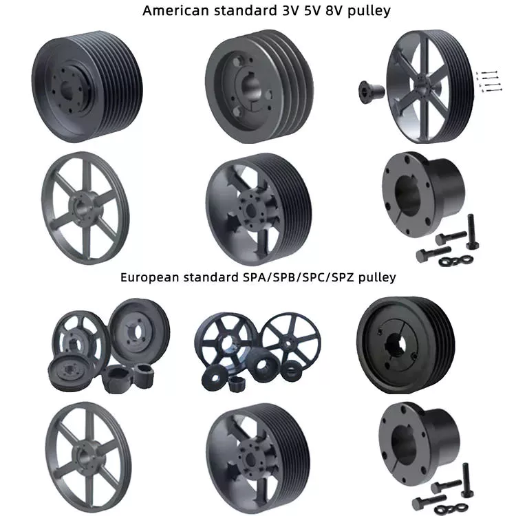
The benefits of using pulleys

A pulley is a mechanical device that converts force into rotation. There are many advantages to using pulleys. Let’s take a look at a few of them. This article will describe the advantages, types, applications, and power sources of pulleys. You can then choose the pulley that best suits your specific needs. If you’re looking for a new tool to help you with a certain task, this article is for you.
pulley

Mechanical advantage

The mechanical advantage of a pulley can be defined as the ratio of applied force to the applied force. The mechanical advantage of a pulley can be calculated by considering several factors, including weight and friction. It can be calculated by the force applied per unit length of rope and the number of pulleys used. In a single-circuit system, the force required to lift a heavy object is equal to the user’s body weight.
The mechanical advantage of a pulley can be realized by comparing it to a seesaw. Both uses of rope are suitable for lifting objects. A rope 4 times heavier than a kilo is 4 times as effective. Because the forces on both sides of the pulley are equal, a small force is enough to move a large weight a short distance. The same force can be applied to a large mass to lift it several meters.
After introducing the concept of mechanical advantage, learners will practice using the pulley system. In addition to testing the pulley system, they should also calculate its mechanical advantage. Using either the instructor-provided handout or the learner’s workbook, students will determine how easily the pulley system functions. Once they have completed the test, they can discuss their results and how the system can be improved. These courses are best completed as part of a mini-unit or as a standalone main course.
The mechanical advantage of the pulley system is proportional to the number of rope loops. This circuit requires the same force as the dual circuit to lift heavy objects. A single lap requires only a third of the force to lift a double lap, while 3 laps require almost half the energy required for a single lap. The mechanical advantage of the pulley system becomes constant as the number of cycles increases.
The 3:1 Mechanical Advantage system feels like lifting a 300-pound load with 3 feet of rope. The three-foot-long rope moves the load 1 foot high. Understanding the mechanical advantages of pulleys is critical for rescuers when trying to create the perfect pulley system. Ideally, the pulley system will be anchored to a nearby rock, tree, pole or person – if the weight is not too heavy.
pulley

Types of pulleys

There are several types of pulleys. V-belt pulleys are the type commonly used in vehicles and electric motors. “V” pulleys require a “V” belt, and some even have multiple V grooves. “V” pulleys are often used in heavy duty applications for power transmission because they reduce the risk of power slippage.
Composite pulleys combine the properties of fixed and movable pulleys. Compound pulleys are able to change the direction of force while requiring relatively low force to move even the heaviest loads. Mechanical advantage is a measure of the effectiveness of a machine or equipment. It can be divided into 3 categories: force, distance and mechanics. Once you understand how each type works, you can design complex machines.
Fixed pulleys: These pulleys are the most basic type of pulleys. They use ropes and slotted wheels to move with the lifted object. Because they are so simple to set up, lifting heavy objects is a breeze. Although the moving object feels light, it is actually heavier than it actually is. These pulleys are used in construction cranes, utility elevators and many different industries.
Compound Pulley System: A pulley pulley is a combination of 2 fixed pulleys and 1 movable pulley. Compound pulley systems are effective for moving heavy objects because they have the largest force multipliers and are flexible enough to change the direction of the force as needed. Composite pulley systems are commonly used in rock climbing, theater curtains and sailing. If you’re looking for a pulley system, you can start by evaluating the types of pulleys and their uses.
Construction Pulleys: These are the most basic types of pulleys and have wheel rails. These pulleys can be lifted to great heights and attached to chains or ropes. They allow workers to access equipment or materials from greater heights. They are usually mounted on wheels with axles and secured with ropes. They are essential tools for construction workers. There are many different types of pulleys out there.

energy source

Belts and pulleys are mechanical devices used to transmit energy and rotational motion. The belt is connected to the rotating part of the energy source, and the pulley is mounted on the other. One pulley transmits power to the other, while the other changes the direction of the force. Many devices use this combination, including automobiles, stationary generators, and winches. It is used in many home applications, from conveyors to treadmills. Pulleys are also used for curtains in theater halls.
Pulley systems are an essential part of modern industry and everyday life. Pulleys are used in elevators, construction sites and fitness equipment. They are also used in belt-driven generators as backup power. Despite their simple and seemingly humble beginnings, they have become a versatile tool. From lifting heavy objects to guiding wind turbines, pulley systems are widely used in our daily lives.
The main reason why pulleys are so popular is the mechanical advantage they offer. They can lift a lot of weight by applying very little force over longer distances. For example, a small motor can pull 10 meters of cable, while a large motor can pull 1 meter. Also, the work done is equal to the force times the distance traveled, so the energy delivered to the large motor is the same.
The power source for the pulley system can be cables, belts or ropes. The drive element in a pulley system is usually a rope or cable. A belt is a loop of flexible material that transmits motion from 1 pulley to another. The belt is attached to the shaft and a groove is cut in the pulley. The belt then transfers energy from 1 pulley to the other through the system.
pulley

application

A pulley is a mechanical device used to lift heavy objects. They reduce the amount of work required to lift heavy objects and are an excellent choice for many applications. There are several different applications for pulleys, including elevators, grinders, planters, ladder extensions, and mountaineering or rock climbing. Let’s take a look at some of the most popular uses for pulleys in modern society. These include:-
A pulley is a mechanical device that changes force. To use, you wrap the rope around it and pull down to lift the object. While this device is very useful, a major limitation of using pulleys is that you still have to apply the same force to lift the object as you would without the pulleys. This is why people use pulleys to move large objects like furniture and cars.
In addition to lifting heavy objects, pulleys are used in elevators, flagpoles and wells. These systems allow people to move heavy objects without straining their backs. Many other examples of pulleys in the home include garage doors, flagpoles, and elevators. They also help raise and lower flagpoles, which can reach several stories high.
There are 2 basic types of pulleys: movable and fixed. Fixed pulleys are attached to a ceiling or other object using 2 ropes. Modern elevators and construction cranes use movable pulleys, as do some weight machines in gyms. Composite pulleys combine movable and fixed pulleys to minimize the force required to move heavy objects.
Another type of fixed pulley is the flagpole. A flagpole can support a country, organization, or anything else that needs to be lifted. A taller flagpole creates a prouder moment for those who support it. The operation of the rope and pulley mechanism is very simple. The user simply attaches the flag to the rope, pulls the pulley, and he or she can watch the flag rise and unfold.

China high quality American 13t Axle and Parts for Semi Trailer Tractor     with Best SalesChina high quality American 13t Axle and Parts for Semi Trailer Tractor     with Best Sales

China manufacturer Power Tiller Walking Tractor Agricultural Machinery Parts with Best Sales

Product Description

Professional in Agricultural Machinery & Accessories in China for 15 years

Our 1GK-series rotary tillers are carefully designed according to different soil qualities. They can be used with various types of tractors for rotary tillage, crushing and stubble burying operations. There is no ridge, the surface is fine and smooth, and the stubble burial rate reaches more than 90%.

The 1GK series rotary tiller have a multi-functional and high-efficiency supporting machine promoted by governments at all levels. The through-shaft type can be used for positive and negative rotary tillage, for different users to choose,and has won many national patents.

Note: Samples under USD 200 are free to provide. We have advantage on agricultural machinery parts. We have more than 9,000 series of conponents of many machines.
For samples, normally we use DHL, fedex, UPS, TNT andEMS. If you have inquyiry, welcome to contact with us.


Guide to Drive Shafts and U-Joints

If you’re concerned about the performance of your car’s driveshaft, you’re not alone. Many car owners are unaware of the warning signs of a failed driveshaft, but knowing what to look for can help you avoid costly repairs. Here is a brief guide on drive shafts, U-joints and maintenance intervals. Listed below are key points to consider before replacing a vehicle driveshaft.
air-compressor

Symptoms of Driveshaft Failure

Identifying a faulty driveshaft is easy if you’ve ever heard a strange noise from under your car. These sounds are caused by worn U-joints and bearings supporting the drive shaft. When they fail, the drive shafts stop rotating properly, creating a clanking or squeaking sound. When this happens, you may hear noise from the side of the steering wheel or floor.
In addition to noise, a faulty driveshaft can cause your car to swerve in tight corners. It can also lead to suspended bindings that limit overall control. Therefore, you should have these symptoms checked by a mechanic as soon as you notice them. If you notice any of the symptoms above, your next step should be to tow your vehicle to a mechanic. To avoid extra trouble, make sure you’ve taken precautions by checking your car’s oil level.
In addition to these symptoms, you should also look for any noise from the drive shaft. The first thing to look for is the squeak. This was caused by severe damage to the U-joint attached to the drive shaft. In addition to noise, you should also look for rust on the bearing cap seals. In extreme cases, your car can even shudder when accelerating.
Vibration while driving can be an early warning sign of a driveshaft failure. Vibration can be due to worn bushings, stuck sliding yokes, or even springs or bent yokes. Excessive torque can be caused by a worn center bearing or a damaged U-joint. The vehicle may make unusual noises in the chassis system.
If you notice these signs, it’s time to take your car to a mechanic. You should check regularly, especially heavy vehicles. If you’re not sure what’s causing the noise, check your car’s transmission, engine, and rear differential. If you suspect that a driveshaft needs to be replaced, a certified mechanic can replace the driveshaft in your car.
air-compressor

Drive shaft type

Driveshafts are used in many different types of vehicles. These include four-wheel drive, front-engine rear-wheel drive, motorcycles and boats. Each type of drive shaft has its own purpose. Below is an overview of the 3 most common types of drive shafts:
The driveshaft is a circular, elongated shaft that transmits torque from the engine to the wheels. Drive shafts often contain many joints to compensate for changes in length or angle. Some drive shafts also include connecting shafts and internal constant velocity joints. Some also include torsional dampers, spline joints, and even prismatic joints. The most important thing about the driveshaft is that it plays a vital role in transmitting torque from the engine to the wheels.
The drive shaft needs to be both light and strong to move torque. While steel is the most commonly used material for automotive driveshafts, other materials such as aluminum, composites, and carbon fiber are also commonly used. It all depends on the purpose and size of the vehicle. Precision Manufacturing is a good source for OEM products and OEM driveshafts. So when you’re looking for a new driveshaft, keep these factors in mind when buying.
Cardan joints are another common drive shaft. A universal joint, also known as a U-joint, is a flexible coupling that allows 1 shaft to drive the other at an angle. This type of drive shaft allows power to be transmitted while the angle of the other shaft is constantly changing. While a gimbal is a good option, it’s not a perfect solution for all applications.
CZPT, Inc. has state-of-the-art machinery to service all types of drive shafts, from small cars to race cars. They serve a variety of needs, including racing, industry and agriculture. Whether you need a new drive shaft or a simple adjustment, the staff at CZPT can meet all your needs. You’ll be back on the road soon!

U-joint

If your car yoke or u-joint shows signs of wear, it’s time to replace them. The easiest way to replace them is to follow the steps below. Use a large flathead screwdriver to test. If you feel any movement, the U-joint is faulty. Also, inspect the bearing caps for damage or rust. If you can’t find the u-joint wrench, try checking with a flashlight.
When inspecting U-joints, make sure they are properly lubricated and lubricated. If the joint is dry or poorly lubricated, it can quickly fail and cause your car to squeak while driving. Another sign that a joint is about to fail is a sudden, excessive whine. Check your u-joints every year or so to make sure they are in proper working order.
Whether your u-joint is sealed or lubricated will depend on the make and model of your vehicle. When your vehicle is off-road, you need to install lubricable U-joints for durability and longevity. A new driveshaft or derailleur will cost more than a U-joint. Also, if you don’t have a good understanding of how to replace them, you may need to do some transmission work on your vehicle.
When replacing the U-joint on the drive shaft, be sure to choose an OEM replacement whenever possible. While you can easily repair or replace the original head, if the u-joint is not lubricated, you may need to replace it. A damaged gimbal joint can cause problems with your car’s transmission or other critical components. Replacing your car’s U-joint early can ensure its long-term performance.
Another option is to use 2 CV joints on the drive shaft. Using multiple CV joints on the drive shaft helps you in situations where alignment is difficult or operating angles do not match. This type of driveshaft joint is more expensive and complex than a U-joint. The disadvantages of using multiple CV joints are additional length, weight, and reduced operating angle. There are many reasons to use a U-joint on a drive shaft.
air-compressor

maintenance interval

Checking U-joints and slip joints is a critical part of routine maintenance. Most vehicles are equipped with lube fittings on the driveshaft slip joint, which should be checked and lubricated at every oil change. CZPT technicians are well-versed in axles and can easily identify a bad U-joint based on the sound of acceleration or shifting. If not repaired properly, the drive shaft can fall off, requiring expensive repairs.
Oil filters and oil changes are other parts of a vehicle’s mechanical system. To prevent rust, the oil in these parts must be replaced. The same goes for transmission. Your vehicle’s driveshaft should be inspected at least every 60,000 miles. The vehicle’s transmission and clutch should also be checked for wear. Other components that should be checked include PCV valves, oil lines and connections, spark plugs, tire bearings, steering gearboxes and brakes.
If your vehicle has a manual transmission, it is best to have it serviced by CZPT’s East Lexington experts. These services should be performed every 2 to 4 years or every 24,000 miles. For best results, refer to the owner’s manual for recommended maintenance intervals. CZPT technicians are experienced in axles and differentials. Regular maintenance of your drivetrain will keep it in good working order.

China manufacturer Power Tiller Walking Tractor Agricultural Machinery Parts     with Best SalesChina manufacturer Power Tiller Walking Tractor Agricultural Machinery Parts     with Best Sales

factory

Types of Ball Bearings

Modern ball bearing configurations have different materials and geometries to meet the demands of different working environments and applications. There are different types of ball bearings: single row deep groove, double-row deep groove, angular contact ball bearing, thrust, and self-aligning. Let us look at the differences between each type and learn why they are important for various purposes. Listed below are some of the most common types of ball bearings.

Miniature bearings

Although miniature ball bearings are a popular choice for small mechanical components, they are not without their challenges. They must be properly lubricated and stored in clean rooms. A strand of hair could ruin a miniature bearing. Fortunately, manufacturers offer lubrication services and a “Clean Room” for customers to store their miniature bearings safely. Read on to learn more about these small bearings and how they can help you.
The size of a miniature ball bearing can vary significantly, but most types of these devices are available in sizes ranging from.040 inch to 1 eighth of an inch. Whether you need a small ball bearing for a miniature car or a tiny instrument, a miniature bearing can save space while still offering high performance. Many of these bearings are shielded to prevent dirt from entering and leakage of lubricant. They can be flanged or unflanged, and some miniature ball bearings have extended inner rings that are designed for easy plate mounting.
Miniature ball bearings are commonly made from stainless steel or chrome steel. Both metals have their advantages. Stainless steel is the most popular material for ball bearings, which allows for a high load capacity while being quiet. Because stainless steel is relatively inexpensive, many small instrument bearings are made entirely of stainless steel. The difference in price is minimal, as the amount of steel is relatively small. Stainless steel miniature bearings are the smallest and lightest of all types of miniature ball bearings.

Self-aligning ball bearings

bearing
In the simplest terms, self-aligning ball bearings are ball bearings with flex shafts. If you’re looking for a ball bearing with a high degree of precision, you’ll want to choose 1 with a flex shaft, which means it can adjust to the proper orientation of the bearing’s flex shaft. Ball bearings with flex shafts are also recommended. But, what are these bearings?
Self-aligning ball bearings are made with 2 rows of balls and a common sphered raceway on the outer ring. As a result, they can accommodate small errors in shaft alignment and mounting. The CZPT brand is especially suitable for high-speed applications requiring greater running accuracy. The self-alignment mechanism is enabled by the fact that the balls are placed in 2 rows on either side of the sphered raceway in the outer ring. These 2 rows of balls also promote reduced friction and wear.
Another type of self-aligning ball bearings is a double-row design. They feature a common sphered raceway on the outer ring, a hollow spherical ring, and a cage that rotates relative to it. A self-aligning ball bearing is used in applications where shaft misalignment is a problem, such as conveying equipment. They are also used in simple woodworking machinery and ventilators.

Ceramic ball bearings

Ceramic ball bearings have several advantages over steel or metal bearings. These include increased acceleration capability, reduced friction, improved wear-resistance, and higher speeds. The United States holds the leading position in the global ceramic ball bearings market thanks to a rebounding motor vehicle production and healthy fixed investment environment. In the United States, there are 3 primary markets for ceramic ball bearings: healthcare, automotive, and aerospace. Here are the main benefits of ceramic ball bearings:
Hybrid ball bearings are also available. Hybrid bearings feature traditional metal rings and silicon nitride (ceramic) balls. Hybrid bearings offer important performance advantages over all-steel bearings, and they are more affordable. However, full ceramic ball bearings have all ceramic parts, and are best suited for machines that require high precision. These types of bearings also resist corrosion and wear.
Compared to steel ball bearings, ceramic balls are lighter than steel. They are also less dense, which means less friction and therefore less heat. Additionally, ceramic balls operate at higher speeds than steel balls, which increases their durability and longevity. But they are still not as strong as steel bearings. And because of their reduced density, they are much cheaper to manufacture. Therefore, they are an excellent choice for many applications. You can expect them to last much longer than steel bearings.

Steel carbon ball bearings

High precision G25 ball bearings are made of the highest grade chrome steel and hot forged from bar stock. Statistical process control and exacting atmospheres help ensure uniform hardness and microstructure. Moreover, these bearings are of the highest quality, with fine surface finish and a tight tolerance. This makes them the most widely used and reliable choice for industrial and automotive applications. However, there are some considerations that should be taken into account before acquiring a steel carbon ball bearing.
Generally, AFBMA grade 200 is the standard hardness specification for this material. AFBMA grade 100 can also be obtained with great difficulty. Despite the high hardness of steel carbon ball bearings, their outer surface is just a thin hardened shell, so a special micro hardness test is needed to evaluate them. In addition to the hardness, steel balls are easily machined and ground. Some manufacturers even offer stainless steel ball bearings and ball sets.
Another factor that makes steel carbon ball bearings so valuable is their precision. They can give precise measurements, which makes them ideal for low and medium-speed applications. Due to their high precision and durability, steel carbon ball bearings can be used in many applications, from conveyor machines to roller skates. However, you should be aware that the material used to produce these bearings is not suitable for applications in which they are exposed to water and gases. Further, they are also noisy and heavy, and must be installed properly in a manufacturing environment.

Stainless steel ball bearings

bearing
Stainless steel ball bearings are made from a high-quality type of stainless steel, 440C, which offers optimal corrosion and abrasion resistance. These bearings are also durable and rust-free, and are suitable for a variety of applications. Among others, stainless steel ball bearings are used in beverage and food processing plants, pharmaceuticals, pulp and paper mills, marine environments, and freezers.
Stainless steel bearings are available in various grades. For example, AISI 440C offers corrosion resistance, while the DD400 is specifically designed for marine applications. Both types of stainless steel are available in different forms, including open, shielded, and sealed. Stainless steel ball bearings can also be custom-made, as BL is known for producing customized bearings. There are also other materials that are available.
AISI type 316 stainless steel balls are ideal for marine applications and food processing. They have excellent resistance to most organic materials and are also used in medical devices and dispenser pumps. They are also strong enough to resist many petroleum products and are widely used in medical equipment and cosmetic applications. In addition, stainless steel balls can be plated to provide an additional layer of protection against chemicals. To understand how they differ, let’s take a look at some common types of stainless steel ball bearings.

Stainless steel

Stainless steel ball bearings can be used in various applications. Besides being corrosion resistant, they also last longer thanks to the Molded-Oil lubrication technology. Stainless steel ball bearings are clean units, which saves time and money in terms of maintenance, replacement, and downtime. But what are the advantages of stainless steel ball bearings? Let us discuss these benefits. Also, we’ll discuss their advantages and disadvantages.
Stainless steel ball bearings offer notable advantages, including corrosion resistance, increased strength, and improved stability under high temperatures. These qualities make them the ideal choice for special circumstances and demanding environments. However, you should be careful when choosing stainless steel bearings. There are several different types of stainless steel. Here’s a brief look at what makes them the best choice. And remember: Stainless steels are also recyclable. In fact, they can be recycled indefinitely.
They’re made from chrome alloy electric furnace steel, which is hardened for optimum service life and strength. They have the highest surface finish and dimensional accuracy. Advanced heat-treating processes increase their strength and anti-cracking abilities. And thanks to their unique materials, they’re corrosion-resistant. As a result, they’re more durable than other types of bearings. And since they’re made with a high-quality steel, you’ll save money in the long run.

Plastic ball bearings

bearing
Plastic ball bearings were developed to meet the specific needs of applications where standard steel bearings would fail. Steel and 440C stainless steel are both susceptible to rusting when exposed to water, making them poor choices for applications involving food processing, swimming pools, and medical equipment. In addition to this, the plastic material is able to dampen vibrations and make the bearing virtually silent. Here’s what makes plastic ball bearings so great for these applications.
Plastic ball bearings are lightweight, corrosion-resistant, and offer a long service life. In addition to their low price, they can be easily cleaned and are incredibly durable. Motion plastics specialist igus has recently expanded its range of xiros polymer grooved ball bearings. These bearings are also FDA-compliant, lubricant-free, electrically insulating, and resistant to both temperature and media.
Plastic bearings are often mounted into other components like wheels, pulleys, and housings. In this way, the inner ring is essentially a profile of the pulley’s profile, and the outer ring is a shaft or fixing clip. The result is seamless integration of the bearing and the surrounding parts, which reduces the overall assembly time and costs. You can also use multiple plastic ball bearings in 1 application for more options.

factory factory

China Standard Plastic Parts Made by Plastic Injection Mold/Mould for ABS Pet Hair Dryer Plastic Case with Hot selling

Product Description

Product Description


 Plastic Injection Product Description:
 

Item Plastic injection moulding parts Plastic material ABS,PP,Nylon,PC or any other material as you need
Type of enterprise Professional manufacturer of injection molds and injection molding parts Service
 
OEM,Design based on your idea or Make mold and produce based on your drawing
Design software Solidworks, Pro-E, UG, CAD, Rhino etc. Drawing format Step, Igs, PDF, CAD etc.
Produce Size
 
From small to big, based on your drawing or sample Product weight
 
1g-10kgs
MOQ 100PCS Production ability 10,000pcs/day
Assembly & Test Professional assembly factory with 6 assembly lines Package
 
Standard carton, pallet or customized package
Payment details T/T, L/C, D/A, D/P, Western Union, MoneyGram, Veem, Paypal etc Delivery time For mold & samples: 3-4 weeks.
For mass production: 15 workdays
Shipping way By Courier DHL, Fedex, TNT, UPS, EMS, By Sea or By Air Prototype 3D printing, CNC, Laser cutting etc

Detailed Photos


Packaging & Shipping


Company Profile


HangZhou CEMAL ENGINEERING CO.,LTD

CEMAL Enginnering , professional plastic mold manufacturer in China, we focus on design and manufacturing plastic molds for the Automotive, Home Appliances and other sectors.
Excited and ready to help support your project from the early stages of part development and tool design to fabrication and parts production via professional engineering, manufacturing, and project management, we are confident that our service level is second to none.
When you choose CEMAL- whether it’s for a single part, a small run or a multi-year contract – you’ll get the same attention to detail, the same problem-solving approach, the same quality solution. That’s the CEMAL promise.
Making our customers satisfying, Keeping our customer successful is the goal of CEMAL.


Why Choose CEMAL

Are you plHangZhou to get a supply of custom injection molds and probably do not have an idea of which Company is likely to offer effective products? If yes, then this article will be a perfect CZPT for you as it tries to highlight various reasons as to why you should choose Loxin mold as your supplier in injection molds. There are thousands of injection mold manufactures in China and therefore, determining the ideal company to partner with can quite be difficult. Not all factories offer genuine products or even provide the various services at affordable prices and there is thus the need to be careful on the company that you settle for.


FAQ


1. Are you a trading company or a manufacturer?
We are a manufacturer as you can see our workshop as above.

2. What kind of trade terms can you do?

EX-WORKS,FOB,CIF,DDP DDU

3. What is your terms of payment?

50% Mold cost deposit,balance mold cost +50% production cost paid when samples confimed,Balance production cost paid against copy
of B/L. We accept T/T

4. Do you support OEM ?

Yes, we can produce by technical drawings or samples.

5. How about your delivery time?

Generally, it take 20-30 working days ( 15-25 days do mold and 5-10 days do mass production).


Screws and Screw Shafts

A screw is a mechanical device that holds objects together. Screws are usually forged or machined. They are also used in screw jacks and press-fitted vises. Their self-locking properties make them a popular choice in many different industries. Here are some of the benefits of screws and how they work. Also read about their self-locking properties. The following information will help you choose the right screw for your application.

Machined screw shaft

A machined screw shaft can be made of various materials, depending on the application. Screw shafts can be made from stainless steel, brass, bronze, titanium, or iron. Most manufacturers use high-precision CNC machines or lathes to manufacture these products. These products come in many sizes and shapes, and they have varying applications. Different materials are used for different sizes and shapes. Here are some examples of what you can use these screws for:
Screws are widely used in many applications. One of the most common uses is in holding objects together. This type of fastener is used in screw jacks, vises, and screw presses. The thread pitch of a screw can vary. Generally, a smaller pitch results in greater mechanical advantage. Hence, a machined screw shaft should be sized appropriately. This ensures that your product will last for a long time.
A machined screw shaft should be compatible with various threading systems. In general, the ASME system is used for threaded parts. The threaded hole occupies most of the shaft. The thread of the bolt occupy either part of the shaft, or the entire one. There are also alternatives to bolts, including riveting, rolling pins, and pinned shafts. These alternatives are not widely used today, but they are useful for certain niche applications.
If you are using a ball screw, you can choose to anneal the screw shaft. To anneal the screw shaft, use a water-soaked rag as a heat barrier. You can choose from 2 different options, depending on your application. One option is to cover the screw shaft with a dust-proof enclosure. Alternatively, you can install a protective heat barrier over the screw shaft. You can also choose to cover the screw shaft with a dust-proof machine.
If you need a smaller size, you can choose a smaller screw. It may be smaller than a quarter of an inch, but it may still be compatible with another part. The smaller ones, however, will often have a corresponding mating part. These parts are typically denominated by their ANSI numerical size designation, which does not indicate threads-per-inch. There is an industry standard for screw sizes that is a little easier to understand.
screwshaft

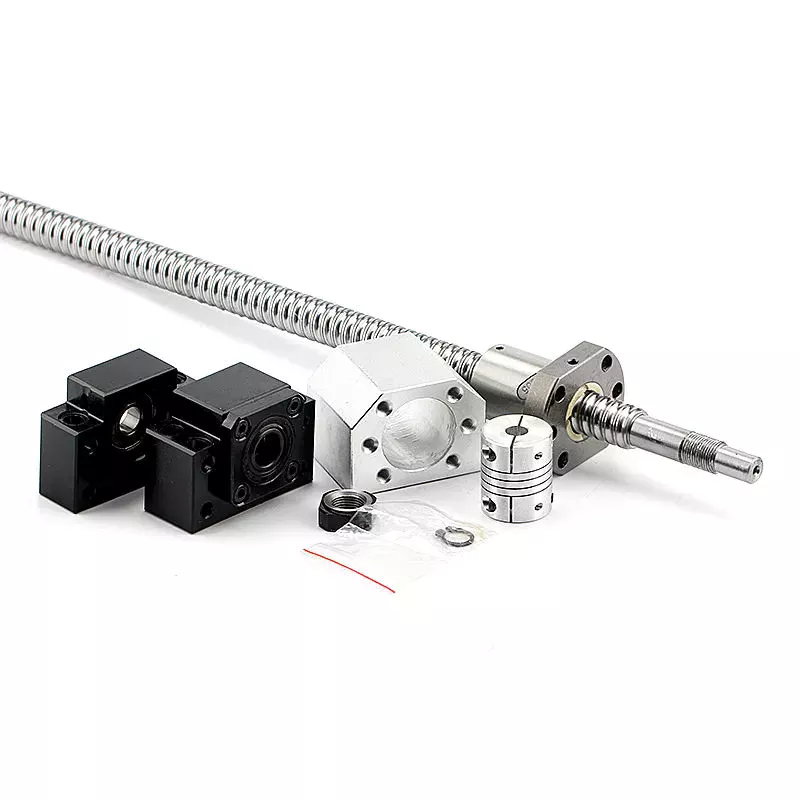
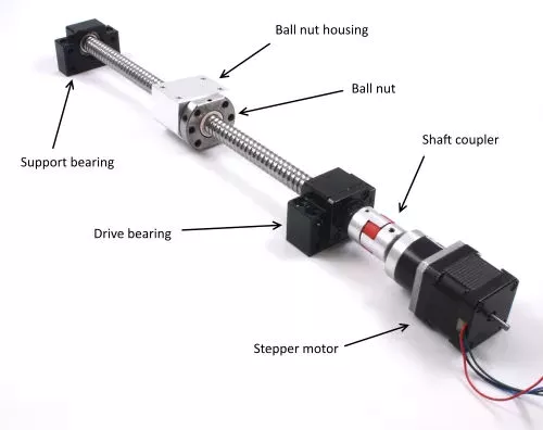
Ball screw nut

When choosing a Ball screw nut for a screw shaft, it is important to consider the critical speed of the machine. This value excites the natural frequency of a screw and determines how fast it can be turned. In other words, it varies with the screw diameter and unsupported length. It also depends on the screw shaft’s diameter and end fixity. Depending on the application, the nut can be run at a maximum speed of about 80% of its theoretical critical speed.
The inner return of a ball nut is a cross-over deflector that forces the balls to climb over the crest of the screw. In 1 revolution of the screw, a ball will cross over the nut crest to return to the screw. Similarly, the outer circuit is a circular shape. Both flanges have 1 contact point on the ball shaft, and the nut is connected to the screw shaft by a screw.
The accuracy of ball screws depends on several factors, including the manufacturing precision of the ball grooves, the compactness of the assembly, and the set-up precision of the nut. Depending on the application, the lead accuracy of a ball screw nut may vary significantly. To improve lead accuracy, preloading, and lubrication are important. Ewellix ball screw assembly specialists can help you determine the best option for your application.
A ball screw nut should be preloaded prior to installation in order to achieve the expected service life. The smallest amount of preload required can reduce a ball screw’s calculated life by as much as 90 percent. Using a lubricant of a standard grade is recommended. Some lubricants contain additives. Using grease or oil in place of oil can prolong the life of the screw.
A ball screw nut is a type of threaded nut that is used in a number of different applications. It works similar to a ball bearing in that it contains hardened steel balls that move along a series of inclined races. When choosing a ball screw nut, engineers should consider the following factors: speed, life span, mounting, and lubrication. In addition, there are other considerations, such as the environment in which the screw is used.
screwshaft

Self-locking property of screw shaft

A self-locking screw is 1 that is capable of rotating without the use of a lock washer or bolt. This property is dependent on a number of factors, but 1 of them is the pitch angle of the thread. A screw with a small pitch angle is less likely to self-lock, while a large pitch angle is more likely to spontaneously rotate. The limiting angle of a self-locking thread can be calculated by calculating the torque Mkdw at which the screw is first released.
The pitch angle of the screw’s threads and its coefficient of friction determine the self-locking function of the screw. Other factors that affect its self-locking function include environmental conditions, high or low temperature, and vibration. Self-locking screws are often used in single-line applications and are limited by the size of their pitch. Therefore, the self-locking property of the screw shaft depends on the specific application.
The self-locking feature of a screw is an important factor. If a screw is not in a state of motion, it can be a dangerous or unusable machine. The self-locking property of a screw is critical in many applications, from corkscrews to threaded pipe joints. Screws are also used as power linkages, although their use is rarely necessary for high-power operations. In the archimedes’ screw, for example, the blades of the screw rotate around an axis. A screw conveyor uses a rotating helical chamber to move materials. A micrometer uses a precision-calibrated screw to measure length.
Self-locking screws are commonly used in lead screw technology. Their pitch and coefficient of friction are important factors in determining the self-locking property of screws. This property is advantageous in many applications because it eliminates the need for a costly brake. Its self-locking property means that the screw will be secure without requiring a special kind of force or torque. There are many other factors that contribute to the self-locking property of a screw, but this is the most common factor.
Screws with right-hand threads have threads that angle up to the right. The opposite is true for left-hand screws. While turning a screw counter-clockwise will loosen it, a right-handed person will use a right-handed thumb-up to turn it. Similarly, a left-handed person will use their thumb to turn a screw counter-clockwise. And vice versa.
screwshaft

Materials used to manufacture screw shaft

Many materials are commonly used to manufacture screw shafts. The most common are steel, stainless steel, brass, bronze, and titanium. These materials have advantages and disadvantages that make them good candidates for screw production. Some screw types are also made of copper to fight corrosion and ensure durability over time. Other materials include nylon, Teflon, and aluminum. Brass screws are lightweight and have aesthetic appeal. The choice of material for a screw shaft depends on the use it will be made for.
Shafts are typically produced using 3 steps. Screws are manufactured from large coils, wire, or round bar stock. After these are produced, the blanks are cut to the appropriate length and cold headed. This cold working process pressudes features into the screw head. More complicated screw shapes may require 2 heading processes to achieve the desired shape. The process is very precise and accurate, so it is an ideal choice for screw manufacturing.
The type of material used to manufacture a screw shaft is crucial for the function it will serve. The type of material chosen will depend on where the screw is being used. If the screw is for an indoor project, you can opt for a cheaper, low-tech screw. But if the screw is for an outdoor project, you’ll need to use a specific type of screw. This is because outdoor screws will be exposed to humidity and temperature changes. Some screws may even be coated with a protective coating to protect them from the elements.
Screws can also be self-threading and self-tapping. The self-threading or self-tapping screw creates a complementary helix within the material. Other screws are made with a thread which cuts into the material it fastens. Other types of screws create a helical groove on softer material to provide compression. The most common uses of a screw include holding 2 components together.
There are many types of bolts available. Some are more expensive than others, but they are generally more resistant to corrosion. They can also be made from stainless steel or aluminum. But they require high-strength materials. If you’re wondering what screws are, consider this article. There are tons of options available for screw shaft manufacturing. You’ll be surprised how versatile they can be! The choice is yours, and you can be confident that you’ll find the screw shaft that will best fit your application.

China Standard Plastic Parts Made by Plastic Injection Mold/Mould for ABS Pet Hair Dryer Plastic Case     with Hot sellingChina Standard Plastic Parts Made by Plastic Injection Mold/Mould for ABS Pet Hair Dryer Plastic Case     with Hot selling

China Good quality Machinery Part Rock CZPT Trencher Chain Civil Construction Bucket Tool with Best Sales

Product Description

Product Description
1.High performance and high efficiency.
2.Wear-resistant carbide tip for extended tooth life.
3.Strong braze weld for superior tip retention.
4.Specially hardened head for much longer tooth life.
5.Fully ranged products with superior quality.
6.Good after-sales service.
7.Strictly inspection and test.
8.On time delivery 

 Advantages:

1.High performance& price ratio.


2.Wear-resistant carbide tip for extended tooth life.


3. Strong braze weld for superior tip retention.


4.Specially hardened head for much longer tooth life.


5.Fully ranged products.


 (trenching bit teeth, conical bits, bullet teeth, cutter bits, rotary cutter bits, rotary drill bit, carbide bullet teeth)


 Model: We can also produce according to your drawings or samples.

Pick for trenching

Model

Carbide diameter D1(mm)


D2(mm)


D3(mm)


D4(mm)

Teeth l1(mm)

Total Length L(mm)

ts30c x

16-30

60

30

38

70-90

130-150

ts32c x

16-30

60

30

38

75

135

ts39c x

16-30

60

30

38

73-92

133-152


Pick for  trenching

Model

Carbide diameter D1(mm)

D2(mm)

D3(mm)

h(mm)

l(mm)

Teeth l1(mm)

Total Length L(mm)

ts36c x

16-30

38

35

5

70

80

157


HangZhoung picks are produced by drawing. The computer calculates the weight of the pick and then cuts it. After extrusion by warm extrusion technology, there is no flash burr and no oxide scale. The material utilization rate is over 95%.
The picks are made by temperature extrusion technology. The temperature is extruded at a metal recrystallization temperature. The forming temperature is about 600-800 degrees Celsius. In this temperature range, the metal no longer produces oxidation and CZPT length. Large forging defects can occur in the process of deformation and recrystallization, accompanied by partial normalizing process, which can significantly change the metallographic structure of the tooth body, refine the CZPT and improve the impact toughness of the pick.

WHO WE ARE
Xihu (West Lake) Dis. HangZhoung Drilling Tools Co.,Ltd was established in “2011”, is a professional manufacturer engaged in the research, development, production, sale and service of foundation drilling tools, trenching tools,tunnel tools, coal mining tools, crusher tools, rotary cutter tools, road milling tools , and other Tungsten carbide brazed products. Our products are widely used in railway, highway, tunnel, subway, mine, mine, metallurgy, water conservancy and other industries. 

 We are located in Xihu (West Lake) Dis. County, HangZhou City, ZheJiang Province with convenient transportation access. Dedicated to strict quality control and thoughtful customer service, our experienced staff members are always available to discuss your requirements and ensure full customer satisfaction.
 
WHAT WE DO
In recent years, Depending on the top-technical talents, rich experience in production, sophisticated production equipment, advanced manufacturing technology, scientific management system and excellent after sale service, the company has grown in strength and our company has introduced a series of advanced equipment including drilling machine,welding machine,milling machine,anneal stove and so on. In addition, we have obtained ISO9001 certificates. Selling well in all cities and provinces around China, our products are also exported to clients in such countries and regions as USA, Dubai, Saudi Arabia, Turkey, Israel,Egypt, Singapore,Malaysia ,Indonesia, Vietnam,Korea and so on. We also welcome OEM and ODM orders. Whether selecting a current product from our catalog or seeking engineering assistance for your application, you can talk to our customer service center about your sourcing requirements.
All of staff warmly welcome customers from all over the world to visit and negotiate business.


FAQ

Q: Do you accept sample order?

A: Of course, please contact us for details.

Q: Can you do OEM?
A: Yes, we can.

Q: How do you control the products quality?
A: Each product will be inspected in strict procedure before delivery.

Q: How about your after-sales service?
A: We can offer technology support to slove all problems. If quality problem, goods can be return or replaceable.

Q: What is your delivery time?
A: Based on order quantity, normally it takes 15-30 days for production. Only 2 or 3 days if we have stock on your request size.

Q: What is your payment terms?
A: Usually 30% deposit in advance by TT, the balance paid against delivery; Western Union, Paypal, L/C at sight is also ok
 

CONTACT

Give us your model/quantity, and your other requirement.


The importance of pulleys

A pulley is a wheel that rides on an axle or axle. The purpose of the pulley is to change the direction of the tensioning cable. The cable then transfers the power from the shaft to the pulley. This article explains the importance of pulleys and demonstrates several different uses for this machine. Also, see the Mechanical Advantages section below for the different types. let’s start.
pulley

simple machine

A simple pulley machine is a device used to transfer energy. It consists of a wheel with flexible material on the rim and a rope or chain tied to the other end. Then lift the load using the force applied to the other end. The mechanical advantage of this system is one, as the force applied to the load is the same as the force on the pulley shaft.
A simple pulley machine has many benefits, from the ability to build pyramids to building modern buildings with it. Pulleys are also popular with children because they can perform simple tasks such as lifting toys onto a slide, sliding them off the slide, and lifting them up again. These activities, called “transportation” by child development theorists, allow them to learn about the physics of simple machines in the process.
The mechanism works by using cables to transmit force. The cable is attached to 1 side of the pulley and the other side is pulled by the user. Lift the load by pulling on 1 end and the other end of the rope. Simple pulley machines have many commercial and everyday applications, including helping move large objects. They can be fixed or movable, and can be a combination of both. The present invention is a great tool for any beginner or engineer.

axis

The axle wheel is the basic mechanical part that amplifies the force. It may have originally appeared as a tool to lift buckets or heavy objects from a well. Its operation is demonstrated by large and small gears attached to the same shaft. When applied to an object, the force on the large gear F overcomes the force W on the pinion R. The ratio of these 2 forces is called the mechanical advantage.
The ideal mechanical advantage of shaft pulleys is their radius ratio. A large radius will result in a higher mechanical advantage than a small radius. A pulley is a wheel through which a rope or belt runs. Often the wheels are interconnected with cables or belts for added mechanical advantage. The number of support ropes depends on the desired mechanical advantage of the pulley.
In the design of the axle wheel, the axle is the fulcrum and the outer edge is the handle. In simple terms, wheels and axle pulleys are improved versions of levers. The axle pulley moves the load farther than the lever and connects to the load at the center of the axle. Shaft pulleys are versatile and widely used in construction.

rope or belt

Ropes or pulleys are mechanical devices used to move large masses. The rope supports a large mass and can be moved easily by applying a force equal to 1 quarter of the mass to the loose end. Quad pulleys have 4 wheels and provide the mechanical advantage of 4 wheels. It is often used in factories and workshops. It is also a popular choice in the construction industry. If you are installing a pulley in your vehicle, be sure to follow these simple installation instructions.
First, you need to understand the basics of how a rope or pulley works. The machine consists of 1 or more wheels that rotate on an axle. The rope or belt is wrapped around the pulley and the force exerted on the rope is spread around the pulley. It then transfers the force from 1 end of the rope to the other. The pulley system also helps reduce the force required to lift objects.
Another common rope or pulley is the differential pulley. This is similar to a rope pulley, but consists of 2 pulleys of different radii. The tension in the 2 halves of the rope supports half the load that the live pulley should carry. These 2 different types of pulleys are often used together in composite pulley systems.
pulley

Mechanical advantage

The mechanical advantage is the ratio of the force used to move the load through the pulley system to the force applied. It has been used to measure the effectiveness of pulley systems, but it also requires assumptions about applied forces and weights. In a simple 1:1 pulley system, the weight lifting the weight is the same as the weight of the person pulling the weight. Adding mechanical advantage can help make up for the lack of manpower.
This advantage stems from the mechanical properties of simple machines. It requires less force and takes up less space and time to accomplish the same task. The same effect can also be achieved by applying less force at a distance. Furthermore, this effect is called the output force ratio. The basic working principle of a pulley system is a rope with a fixed point at 1 end. The movable pulley can be moved with very little force to achieve the desired effect.
The load can be moved through the vertical entry using a simple pulley system. It can use a simple “pulley block” system with a 2:1 “ladder frame” or a 4:1 with dual pulleys. This can be combined with another simple pulley system to create a compound pulley system. In this case, a simple pulley system is pulling another pulley, giving it a 9:1 mechanical advantage.

Commonly used

You’ve probably seen pulley systems in your kitchen or laundry room. You probably already use it to hang clothes on an adjustable clothesline. You may have seen motor pulleys in the kitchens of commercial buildings. You might even have seen 1 on a crane. These machines use a pulley system to help them lift heavy loads. The same goes for theaters. Some pulleys are attached to the sides of the stage, enabling the operator to move up and down the stage.
Pulley systems have many uses in the oil and petroleum industry. For example, in the oil and gas industry, pulley systems are used to lay cables. They are arranged in a pulley structure to provide mechanical energy. When the rope is running, 2 pulleys are hung on the derrick to facilitate smooth running. In these applications, pulleys are very effective in lifting heavy objects.
A pulley is a simple mechanical device that converts mechanical energy into motion. Unlike chains, pulleys are designed to transfer power from 1 location to another. The force required to lift an object with a pulley is the same as that required by hand. It takes the same amount of force to lift a bucket of water, but it’s more comfortable to pull sideways. A bucket of water weighs the same as when lifted vertically, so it’s easy to see how this mechanism can be useful.
pulley

Safety Notice

When using pulleys, you should take several safety precautions to keep your employees and other workers on the job site safe. In addition to wearing a hard hat, you should also wear gloves to protect your hands. Using pulleys can lead to a variety of injuries, so it’s important to keep these precautions in mind before using pulleys. Here are some of the most common:
Pulleys are an important piece of equipment to have on hand when lifting heavy objects. Pulleys not only reduce the force required to lift an object, but also the direction of the force. This is especially important if you are lifting heavy objects, such as a lawn mower or motorcycle. Before starting, it is important to make sure that the anchoring system can support the full weight of the object you are lifting.
When using a pulley system, make sure the anchor points are adequate to support the load. Check with the pulley manufacturer to determine the weight it can safely lift. If the load is too large, composite pulleys can be used instead. For vertical lifts, you should use a sprocket set and wear personal protective equipment. Safety precautions when using pulleys are critical to worker health and safety.

China Good quality Machinery Part Rock CZPT Trencher Chain Civil Construction Bucket Tool     with Best SalesChina Good quality Machinery Part Rock CZPT Trencher Chain Civil Construction Bucket Tool     with Best Sales

China Best Sales Rice Combine Hydraulic Parts Retail Cbxw-F with Best Sales

Product Description

Performance character

1. The pump housing was made of higher strength ear-resisting iron-casting material.

2. High-performance seal kits, working medium temperature is -20°C to +120 °C.

3. The auto-compensation unit of axial clearance ensures the high volumetric efficiency.

4. Higher working pressure, wider speed range.

5. Widely applied to the hydraulic system of excavator.


Model Nominal displacement     (ml/r)

Pressure

(bar)


Speed (r/min) Volumetric efficiency
(≥%)
 

Weight

(kg)
 

Rated. Max. Min. Rated. Max.
CBXW-F10-AT** 10 200
 
250
 

800


2000


2500


92


1.9
CBXW-F16.8-AT** 16.8 2.2
CBXW-F20-AT** 20 2.3


Supporting Ball Screws

In order to use a ball screw in a project, it is important to support it for rotation. Typically, this requires holding brackets and roller bearings. Longer screws may require bending or critical speed restraints. End machining may be necessary to fit the screw into the bearing. Connection to a motor requires coupling and appropriate machining. Tables or support rails may be necessary to restrain the nut.

Cost

In this report, you’ll get an in-depth analysis of the ball screw market. You’ll learn about the competitive landscape, product portfolio, and growth prospects across regions. The report will also include information on the market’s various drivers and restraints, as well as the factors driving or restraining its development. You’ll also get an in-depth look at the value chain and PEST analysis, which are important components of a market study.
One resource that you can use to research the Ball Screw market is CZPT. This website contains a database of authentic Indian manufacturers, suppliers, and importers. You’ll find contact details and email addresses of the companies, including those that produce a wide variety of different types of ball screws. CZPT even allows you to search by product category. That way, you can find a supplier based on the type of ball screw you need at the lowest price.
Another benefit of ball screws is their ability to operate in very delicate applications. In electric vehicles, they are often used to replace a common hydraulic system. They are also used to control gates at hydroelectric stations. You can also find them in motorised inspection tables, step photolithography machines, and microscopic integrated circuits. You can find hundreds of different ball screw designs, and you can even purchase them with nuts, wipers, and CZPT. Ball screws have several bearing balls, which help transfer load between nut and screw. They can be available with adjustable preload and non-preloaded options. And they’re manufactured to industry standards to meet the demands of their users.
If you’re looking for a reliable, high-performing screw, you’ll want to opt for a ball screw. These have high performance-to-cost ratios. You’ll need to choose between a lead screw and a ball screw, but both are reliable and efficient. Besides, the former is less expensive and offers great design flexibility. They’re corrosion-resistant and can even be self-locking for vertical applications.
air-compressor

Applications

A ball screw and nut assembly are essential components of a variety of important actuation and control devices. The 2 components rely on the ability of the screw to rotate easily while converting the rotation into precise lateral movement. Ball screws are a common component in computer-controlled motion-control systems. The precision of ball screw rotation is essential for the accurate adjustment of flight control surfaces. In addition, ball screws are important components of wire bonding and computer-controlled motion-control systems.
Ball screws are highly accurate, requiring minimal lead error. The lead error of a screw is the difference between the theoretical and actual distance traveled by the nut during rotation. The lead error of a ball screw depends on several factors, including the manufacturing accuracy of the ball grooves, the compactness of the assembly, and the set-up precision. This error is not constant from lead to lead, but it may be reduced through preloading, lubrication, and increased mounting accuracy.
The ball is urged to move up and down by rotation of the nut, which is preferably a hexagonal shaft. This allows the ball to be raised easily over the land of the screw. It is important to note that the nut has a groove on the outer surface that is deep enough to accommodate a ball. This groove is deep enough to accommodate a ball, and the groove extends the length of the screw, thereby reducing friction and increasing precision.
The recirculated balls in a multi-start ball screw assembly may cross multiple threads and turn in the circuit. Multi-start ball screw assemblies typically use the internal channel method to recirculate balls. This design allows multiple ball nuts to be used in a single nut and can be easily installed. The ball nut and the nut may also be incorporated into several separate circuits. If several recirculation paths are desired, a ball nut and a multi-start system may be used.

Durability

A key feature of ball screws is their durability. During manufacture, a ball screw’s material must be chosen carefully. A corrosion-resistant steel called Cronidur(r) 30 is an ideal choice. Ball screws made from this material are exceptionally reliable in space due to their alternating steel-ceramic architecture. As the conditions of space are extreme, corrosion-resistant materials are essential to ensure optimum performance. CZPT has decades of experience manufacturing high-quality ball screws. Besides providing a complete range of ball screws, the company also offers technological solutions and dedicated components.
CZPT developed a special design for the High-Durability Precision Ball Screw. This design makes it easier to form a thin film of oil on the material’s surface. This oil helps reduce friction and improve the precision of a ball screw. This material’s special microstructure reduces the wear of ball screws and improves their service life. CZPT also aims to improve the wear-resistance of ball screws.
In addition to the axial load, a ball screw’s life rating should be based on the jacking and vertical loads. In other words, if all load balls are in contact with the raceways, the L-10 life rating of ball screw assemblies would be converted to an L-2 life rating. This change would increase the overall reliability of a ball screw to 98%. Then again, it’s important to note that vertical load is the only 1 that would be completely removed from the chart.
In addition to these important considerations, it is essential to operate ball screws within their recommended operating temperature range. Failure to do so could result in thermal expansion of the ball screw, causing positioning errors. To ensure lubrication of the ball screw, it’s important to keep its operating temperature within the recommended range. However, it is possible to operate it at temperatures that are too high. If this occurs, the screw should be sent to the manufacturer for repair.
air-compressor

Size

Besides their obvious use, ball screws come in 2 sizes, large and small. Although small balls should not show significant wear, they should still be used to enhance the screw’s durability. This can be difficult to determine because screw rebuilders tend to overlook this aspect. So, what is the best size for ball screws? This article will look at both sizes and what they mean for the screw’s durability. Also, we’ll look at some of the things to keep in mind when choosing the right size for your project.
A ball screw’s size depends on its application and performance requirements. Some types have small diameters and fine leads, while others feature large diameters. High precision applications often require miniature ball screws. Some manufacturers even offer compact ball screws with a smaller outer diameter. The latter is commonly found in miniature designs and feature diameters up to 25 mm. However, this doesn’t mean that a smaller diameter means less accuracy. Regardless of the size, you’ll want to make sure to select a screw that will meet your requirements.
The screw’s root diameter is a critical measurement in determining critical speed and column load calculations. A ball screw’s minor diameter is the minimum dimension of the screw shaft at the bottom of the ball grooves. In addition, the idler ball is a necessary component of a ball screw. It prevents friction between the load and idler balls, but does not carry the load itself. Likewise, the non-operating load capacity should be large enough to prevent the balls from brinelling and plastic deformation.
The characteristic speed is the rotational speed at which the ball screw begins to vibrate due to dynamic load. Inch/imperial screws are specified for 1 million revolutions, while metric screw has a specific limit for 1 million inches of linear travel. Various manufacturing processes have their own ways to calculate the useful life of ball screw assemblies. For example, Precision Grinding produces the lowest lead errors. In addition, the life of a ball screw depends on the length of the screw and the mounting support for the end bearings.
air-compressor

Maintenance

It is critical to regularly perform PM on your ball screw assemblies to ensure optimal performance. A dirty ball screw assembly will result in poor performance and faster wear, so removing dirt from the nut and shaft is a good idea. If there are problems with the ball nut, the lubricant inside can become stripped or the nut can become dirty due to chemical exposure. You should also check for oxidation or corrosion on the contact surfaces of the ball screw, and replace it if necessary.
The first sign of a deteriorating ball screw is excessive vibration. This may be caused by a bent screw shaft or misaligned bearing housings. If it makes noise when running, this may be due to excessive build-up or a broken return tube. Other issues may be caused by endplay in support bearings or excessive preload or improper lubrication. If any of these problems are found, it is essential to perform regular maintenance on the ball screw to prolong its life.
Getting regular maintenance on the ball screw assembly is important. If the screw is not properly maintained, it may wear out prematurely. If this happens, you can contact a ball screw repair service. CZPT International, Inc., a leading supplier of industrial parts, can help you get the screw back into optimal working order or find a new one. A ball screw repair company can help you avoid the inconvenience of downtime and maximize your productivity.
It is essential to properly lubricate a ball screw assembly in order to prolong its life. Lubrication can prevent corrosion and increase the life of the screw by 85 percent. It is important to remember that the type of lubricant you use should correspond to the load applied to the assembly. Lubrication should also be done at regular intervals. Once you’ve established the right amount of lubrication, you can then apply it on the screw.

China Best Sales Rice Combine Hydraulic Parts Retail Cbxw-F     with Best SalesChina Best Sales Rice Combine Hydraulic Parts Retail Cbxw-F     with Best Sales