Author Archives: ep

China Best Sales High Level Ebony Violin Parts with Craved Flowers near me factory

Product Description

Model  VS-04
Color natural
Material ebony
Including tailpiece,tailpice wire,chinrest,chinrest screw.4 tunners& 1 end pin
MOQ 20 pcs
Size 4/4–1/10

Unlike the traditional violin factory, Sinomusik as a renowned violin supplier in China, it provides the best services to customers like the best price, superior quality, one-on-1 and professional communication, and the advanced after-sales services. Our company is mainly engaged in violin, viola, cello, contrabass, and the related accessories of stringed instruments, such as bows, strings, shoulder rest, and so on. Well-chosen wood, impeccable craftsmanship, prefect handmade, and outstanding tone are CZPT to give customers the ultimate visual, tactile, and auditory experience. Our products are suitable for people of all ages,whether you are novice beginners or professional performers; full-size and multi-priced are available for you to choose.

FAQ

1.What is the  minimum order quantity ?
As first cooperation ,you can choose 1 or 2 pcs models from our stock to check
our handcrafted and sound .If confirmed order ,we can give your MOQ depend on different models
 
2.How long is the quality guarantee ?
For quality guarantee for 1 year  no human damage.
 
3.How long the delivery time?
A.stock models , 1-3days after received payments
B.For OEM, ukulele delivery times: 30 days  or so after received your deposit.
Guitar delivery times: 45 days or so after received your deposit.
 
4.What is your payments terms ?
For stock models : 100% payment before shipment
For OEM/ODM:   30%TT deposit first,  balance before shippment 
 
5.What is the payment methods?
TT /  Western Union/  Paypal
 
6.How much for the shipment cost ?
At first ,please let us know the mode of transport (by express or by air or by sea )
and also please  provide us your address or airport or sea port
and your order quantities,we will check the shipment cost for you asap.
Any questions please feel free to contact me.

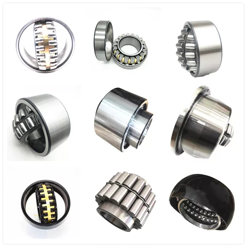
Types of Ball Bearings

If you’re looking to purchase a new ball bearing, there are many different types available. Learn about Single-row designs, Ceramic hybrid bearings, and Self-aligning ball bearings. You can also choose from stainless steel or single-row designs. Then, read about the different types of materials available to you. You’ll have an easier time making a decision. After all, you won’t have to worry about maintaining your new ball bearing, since it will be maintained by your supplier.
bearing

Single-row designs

Ball bearings with a single-row design have a high load-carrying capacity. They are used in applications where high loads must be handled smoothly. A single-row design is a good choice when the material’s properties require high load-carrying capacity but limited axial load capability. Single-row designs use 2 bearings with similar design features, but they have different mounting methods. Single-row designs can be adjusted either against 1 another to accommodate axial loads.
The single-row design is suitable for high-speed applications, but also has some disadvantages. The contact angle a is the angle between the radial plane and contact line. The larger the angle, the higher the axial load carrying capacity of the bearing. Single-row angular contact ball bearings are suitable for higher axial forces. Single-row angular contact ball bearings have a single-row design and support high axial forces in 1 direction. Single-row ball bearings are available in both pressed steel and machined steel cages.
Angular contact ball bearings with a single row feature a cage made of fiber-glass reinforced polyamide 66. These are available in diameters up to 130 mm. Four-point angular contact ball bearings use brass, steel, or brass plate. They have good running properties and a low coefficient of linear expansion. Single-row designs are easy to mount and are widely available. Alternatively, they can be mounted with a universal match design, which allows them to be easily adjusted.
One-row angular contact ball bearings are generally not suitable for angular misalignments because they are unsuitable for compensation of angular misalignments. Misalignments cause internal forces in the bearing which reduce its radial load capacity and life expectancy. This type of bearing is not suitable for adjacent mounting as it increases the chances of misalignment. However, it is a suitable choice for applications where only 1 bearing is required per bearing position.

Ceramic hybrid bearings

While all-ceramic bearings are limited to very specialized applications, Si3N4-based hybrid bearings are finding use in a wide range of high-speed machines. Compared to steel, ceramics are less susceptible to centrifugal forces, which are directly proportional to the mass of the balls. Because Si3N4 replacement balls have a lower density than steel, these bearings reduce the stress placed on the outer race.
The benefits of hybrid bearings are clear: they allow for higher speeds and loads than full-ceramic bearings, and they require no lubrication. Because of their many benefits, many industrial equipment operators are switching to these innovative bearings. CBR is 1 company that specializes in ceramic hybrid bearings and can help you find the best product for your application. If you are thinking about purchasing ceramic bearings for your next machine, here are some things you need to know about them.
A ceramic ball bearing surface has an extremely low coefficient of friction, which is important for applications that require low friction and high speeds. Ceramic balls also have a higher hardness than steel balls, which increases their life. In addition to this, ceramic hybrid bearings have superior thermal properties, generating less heat even when spinning at high speeds. These properties make ceramic hybrid bearings an ideal choice for high-speed machinery, especially electric motors. They are also suitable for applications that operate under water.
A ceramic ball hybrid bearing is much less susceptible to temperature fluctuations and wear. Because they are essentially indestructible, ceramic balls do not generate wear particles from the adhesive wear. They can run at significantly higher speeds than steel balls. Ceramic balls are also more resistant to moisture. For this reason, grease is a recommended lubricant in most ceramic bearing applications. These lubricants offer superior protection against moisture and corrosion. Further, they are available in many types.
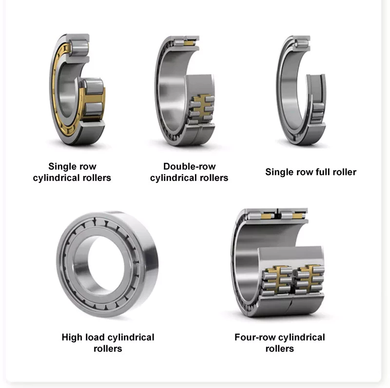
bearing

Self-aligning ball bearings

A self-aligning ball bearing is 1 type of self-aligning bearing. These bearings are recommended for use in flex shaft systems. Their self-aligning feature prevents them from misaligning when in use. They can be used in both single and multiple-joint systems. In addition to self-aligning ball bearings, these units also feature flex shafts.
These self-aligning ball bearings come in a variety of configurations, including cylindrical, round, tapered, and straight bore. Their inner ring is tapered to meet specific tolerances. They are suitable for operating temperatures ranging from -30°F to 120°F. Their wide range of applications allows them to be used in general machinery, precision instruments, and low noise motors. In addition, they are available in a variety of outside diameters, widths, and internal clearances.
Self-aligning ball bearings have 2 rows of balls and 1 common sphered raceway in the outer ring. This enables them to automatically compensate for angular misalignment, which may be caused by machining and assembly errors or deflections. Compared to spherical roller bearings, these self-aligning ball bearings generate less friction. They run cooler even at high speeds. Self-aligning ball bearings also offer free engineering support.
Self-aligning ball bearings are designed for difficult shaft alignment. They are double-row, self-retaining units, with cylindrical or tapered bores. These bearings are available in open and sealed designs, and can also be used in applications with misalignment. They are also available with an outer ring that rotates in relation to the inner ring. When it comes to shaft misalignment, self-aligning ball bearings are a great solution.

Stainless steel

Stainless steel is a metal that resists corrosion and is highly durable. Its corrosion-resistant and water-resistance properties make it a good choice for bearings in food and marine applications. Additionally, stainless steel has hygienic benefits. Here are some of the benefits of stainless steel ball bearings. Read on to learn more about these amazing bearings! We’ve included some of the most common uses for stainless steel.
Hardness is important in a ball bearing. Steel uses the Rockwell C scale to measure hardness. A grade 25 steel ball bearing is accurate to 25 millionths of an inch, while a grade 5 ceramic bearing is less than a half-inch round. Although roundness is important, it shouldn’t be overemphasized, as the bearing surfaces may not be as accurate as the grade of the metal. And remember, a higher price tag doesn’t mean a better product.
Stainless steel ball bearings are available in a variety of alloys. The alloys used in manufacturing a stainless steel ball bearing vary in hardness, strength, and ductility. Stainless steel ball bearings have high corrosion-resistance properties. Additionally, they have long lubrication lives. These benefits make them a popular choice for industrial applications. These bearings are easy to maintain, reduce replacement costs, and offer corrosion resistance.
The NTN Sentinel Series is a premium line of stainless steel bearings. The solid lube is NSF H1 registered and prevents grease from leaching into food. It is also corrosion-resistant and doesn’t need to be coated. The seals and slinger create a water-resistant barrier between the steel ball and the lubricant. It also adds safety and security to the bearing.
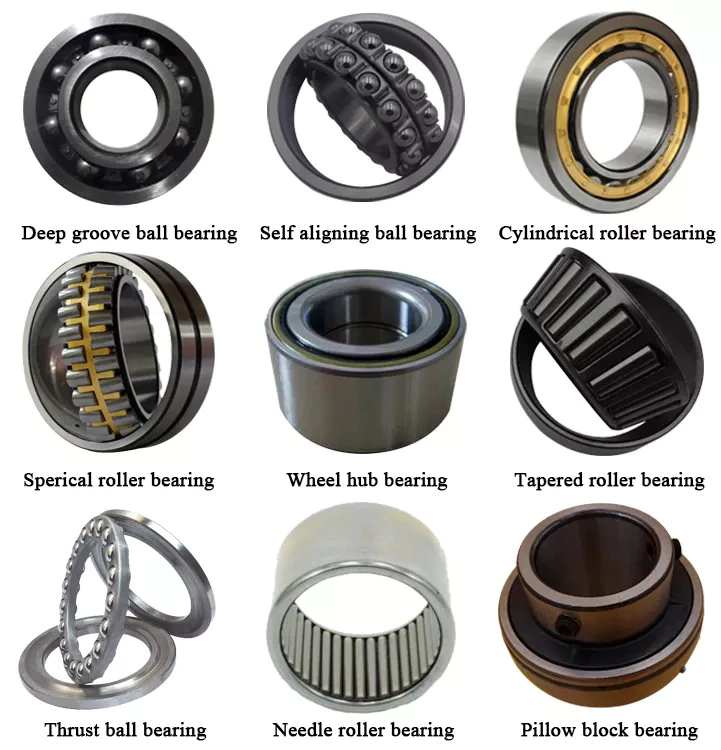
bearing

Plastic balls

For applications where noise and weight are major concerns, plastic balls are ideal. These non-magnetic balls are ideal for MRI X-ray machines and sensors. They are also easy to lubricate, and are non-magnetic. A polymer ball bearing is the lightest of all 3 types. This makes them a good choice for many industries. Read on to learn more. This article will introduce some of the advantages of plastic balls for ball bearings.
Although ceramic ball bearings are more durable and offer many advantages, they are more expensive than plastic. Fortunately, plastic ball bearings offer a cheaper alternative. These bearings feature all-plastic races and cages. Depending on the application, plastic balls can be used in applications involving chemicals. In these cases, plastic ball bearings are available with a C160 grade, which is safe for use in temperatures below 176 deg F.
Medical devices often require precision specialty balls, which are made of glass, stainless steel, and plastic. These bearings must meet stringent cleanliness requirements. To meet the most stringent requirements, they must undergo ultrasonic cleaning. These bearings are available in plastic raceways, and are also available with glass or stainless steel balls. Polyethylene balls are lightweight and can be used in a variety of applications. They can be ordered in different sizes and tolerances to meet specific requirements.
Plastic balls for ball bearings are often mounted into other parts, such as plastic wheels, pulleys, and housings. They can be seamlessly integrated into other parts of a machine, which reduces assembly time and improves affordability. One important advantage of plastic bearings is that they are rust-resistant. As such, they can be used in harsh environments without causing any damage. If a piece of equipment is exposed to extreme temperatures, polymers are the ideal choice.

China Best Sales High Level Ebony Violin Parts with Craved Flowers     near me factory China Best Sales High Level Ebony Violin Parts with Craved Flowers     near me factory

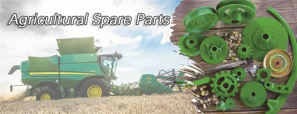
China wholesaler Spare Parts for Combine Harvester CZPT CZPT World near me factory

Product Description

SPARE PARTS FOR COMBINE HARVESTER
Besides our own brand”K-BOS” ,you can also get the parts resourse of CZPT Kutota.
 

How to Select a Worm Shaft and Gear For Your Project

You will learn about axial pitch PX and tooth parameters for a Worm Shaft 20 and Gear 22. Detailed information on these 2 components will help you select a suitable Worm Shaft. Read on to learn more….and get your hands on the most advanced gearbox ever created! Here are some tips for selecting a Worm Shaft and Gear for your project!…and a few things to keep in mind.
worm shaft

Gear 22

The tooth profile of Gear 22 on Worm Shaft 20 differs from that of a conventional gear. This is because the teeth of Gear 22 are concave, allowing for better interaction with the threads of the worm shaft 20. The worm’s lead angle causes the worm to self-lock, preventing reverse motion. However, this self-locking mechanism is not entirely dependable. Worm gears are used in numerous industrial applications, from elevators to fishing reels and automotive power steering.
The new gear is installed on a shaft that is secured in an oil seal. To install a new gear, you first need to remove the old gear. Next, you need to unscrew the 2 bolts that hold the gear onto the shaft. Next, you should remove the bearing carrier from the output shaft. Once the worm gear is removed, you need to unscrew the retaining ring. After that, install the bearing cones and the shaft spacer. Make sure that the shaft is tightened properly, but do not over-tighten the plug.
To prevent premature failures, use the right lubricant for the type of worm gear. A high viscosity oil is required for the sliding action of worm gears. In two-thirds of applications, lubricants were insufficient. If the worm is lightly loaded, a low-viscosity oil may be sufficient. Otherwise, a high-viscosity oil is necessary to keep the worm gears in good condition.
Another option is to vary the number of teeth around the gear 22 to reduce the output shaft’s speed. This can be done by setting a specific ratio (for example, 5 or 10 times the motor’s speed) and modifying the worm’s dedendum accordingly. This process will reduce the output shaft’s speed to the desired level. The worm’s dedendum should be adapted to the desired axial pitch.

Worm Shaft 20

When selecting a worm gear, consider the following things to consider. These are high-performance, low-noise gears. They are durable, low-temperature, and long-lasting. Worm gears are widely used in numerous industries and have numerous benefits. Listed below are just some of their benefits. Read on for more information. Worm gears can be difficult to maintain, but with proper maintenance, they can be very reliable.
The worm shaft is configured to be supported in a frame 24. The size of the frame 24 is determined by the center distance between the worm shaft 20 and the output shaft 16. The worm shaft and gear 22 may not come in contact or interfere with 1 another if they are not configured properly. For these reasons, proper assembly is essential. However, if the worm shaft 20 is not properly installed, the assembly will not function.
Another important consideration is the worm material. Some worm gears have brass wheels, which may cause corrosion in the worm. In addition, sulfur-phosphorous EP gear oil activates on the brass wheel. These materials can cause significant loss of load surface. Worm gears should be installed with high-quality lubricant to prevent these problems. There is also a need to choose a material that is high-viscosity and has low friction.
Speed reducers can include many different worm shafts, and each speed reducer will require different ratios. In this case, the speed reducer manufacturer can provide different worm shafts with different thread patterns. The different thread patterns will correspond to different gear ratios. Regardless of the gear ratio, each worm shaft is manufactured from a blank with the desired thread. It will not be difficult to find 1 that fits your needs.
worm shaft

Gear 22’s axial pitch PX

The axial pitch of a worm gear is calculated by using the nominal center distance and the Addendum Factor, a constant. The Center Distance is the distance from the center of the gear to the worm wheel. The worm wheel pitch is also called the worm pitch. Both the dimension and the pitch diameter are taken into consideration when calculating the axial pitch PX for a Gear 22.
The axial pitch, or lead angle, of a worm gear determines how effective it is. The higher the lead angle, the less efficient the gear. Lead angles are directly related to the worm gear’s load capacity. In particular, the angle of the lead is proportional to the length of the stress area on the worm wheel teeth. A worm gear’s load capacity is directly proportional to the amount of root bending stress introduced by cantilever action. A worm with a lead angle of g is almost identical to a helical gear with a helix angle of 90 deg.
In the present invention, an improved method of manufacturing worm shafts is described. The method entails determining the desired axial pitch PX for each reduction ratio and frame size. The axial pitch is established by a method of manufacturing a worm shaft that has a thread that corresponds to the desired gear ratio. A gear is a rotating assembly of parts that are made up of teeth and a worm.
In addition to the axial pitch, a worm gear’s shaft can also be made from different materials. The material used for the gear’s worms is an important consideration in its selection. Worm gears are usually made of steel, which is stronger and corrosion-resistant than other materials. They also require lubrication and may have ground teeth to reduce friction. In addition, worm gears are often quieter than other gears.

Gear 22’s tooth parameters

A study of Gear 22’s tooth parameters revealed that the worm shaft’s deflection depends on various factors. The parameters of the worm gear were varied to account for the worm gear size, pressure angle, and size factor. In addition, the number of worm threads was changed. These parameters are varied based on the ISO/TS 14521 reference gear. This study validates the developed numerical calculation model using experimental results from Lutz and FEM calculations of worm gear shafts.
Using the results from the Lutz test, we can obtain the deflection of the worm shaft using the calculation method of ISO/TS 14521 and DIN 3996. The calculation of the bending diameter of a worm shaft according to the formulas given in AGMA 6022 and DIN 3996 show a good correlation with test results. However, the calculation of the worm shaft using the root diameter of the worm uses a different parameter to calculate the equivalent bending diameter.
The bending stiffness of a worm shaft is calculated through a finite element model (FEM). Using a FEM simulation, the deflection of a worm shaft can be calculated from its toothing parameters. The deflection can be considered for a complete gearbox system as stiffness of the worm toothing is considered. And finally, based on this study, a correction factor is developed.
For an ideal worm gear, the number of thread starts is proportional to the size of the worm. The worm’s diameter and toothing factor are calculated from Equation 9, which is a formula for the worm gear’s root inertia. The distance between the main axes and the worm shaft is determined by Equation 14.
worm shaft

Gear 22’s deflection

To study the effect of toothing parameters on the deflection of a worm shaft, we used a finite element method. The parameters considered are tooth height, pressure angle, size factor, and number of worm threads. Each of these parameters has a different influence on worm shaft bending. Table 1 shows the parameter variations for a reference gear (Gear 22) and a different toothing model. The worm gear size and number of threads determine the deflection of the worm shaft.
The calculation method of ISO/TS 14521 is based on the boundary conditions of the Lutz test setup. This method calculates the deflection of the worm shaft using the finite element method. The experimentally measured shafts were compared to the simulation results. The test results and the correction factor were compared to verify that the calculated deflection is comparable to the measured deflection.
The FEM analysis indicates the effect of tooth parameters on worm shaft bending. Gear 22’s deflection on Worm Shaft can be explained by the ratio of tooth force to mass. The ratio of worm tooth force to mass determines the torque. The ratio between the 2 parameters is the rotational speed. The ratio of worm gear tooth forces to worm shaft mass determines the deflection of worm gears. The deflection of a worm gear has an impact on worm shaft bending capacity, efficiency, and NVH. The continuous development of power density has been achieved through advancements in bronze materials, lubricants, and manufacturing quality.
The main axes of moment of inertia are indicated with the letters A-N. The three-dimensional graphs are identical for the seven-threaded and one-threaded worms. The diagrams also show the axial profiles of each gear. In addition, the main axes of moment of inertia are indicated by a white cross.

China wholesaler Spare Parts for Combine Harvester CZPT CZPT World     near me factory China wholesaler Spare Parts for Combine Harvester CZPT CZPT World     near me factory

China manufacturer Lawn Tractor Deck Lift Lever Torsion Spring Genuine Original Equipment Manufacturer Part with Free Design Custom

Product Description

Item ISO Certificated Customized Torsion Spring With Different Shape
Wire Diameter 0.1mm-8mm
Inside Diameter >=0.3 mm
Outside Diameter >=0.5 mm
Total Coils >=1
Material Stainless Stee(SUS), Spring Steel(SWC), Music Wire(SWP), Mild-Carbon Steel, Phosphor Copper, Beryllium Copper, Brass, Aluminum, Alloy Steel etc.

Dimensions Customized
Surface Treatment Zinc, Nickel, Chrome, Tin, Silver, Copper, Gold,  Dacromet Plating, Blacking, E-coating, Powder coating etc
Samples Time 3-5 Working Days
Delivery Time 10-25 Days
Experience More than 20 years manufacture experience of springs, wire forms and stamping parts
Payment Terms T/T, West Union, Alibaba Trade Assurance Order
Certification ISO9001:2015, SGS, Rohs
Package PE Bag + Carton

FAQ
 
Q: Are you trading company or manufacturer?

A: We are the factory by SGS authenticated.

Q. When can I get the price?
 
A: We usually quote within 24 hours after we got your inquiry. If you are very urgent to get the price, please call us or contact us by email.

Q: How can I get the quotation?

A: Please send us information for quote: drawing, material, weight, quantity and request, we can accept PDF, ISGS, DWG, STEP file format. If you don’t have drawing, please send the sample to us, we can quote based on your sample too.

 Q. Do you accept the OEM?

 A: OEM is welcome. We can custom the goods according to your design . 
 
Q. What is the shipping?

 A: By express(FedEx, UPS, DHL, TNT, EMS, etc…), By Air and By Sea.
  
Q. How do I pay for the order?

 A: The common payments are T/T(Telegraphic Transfer), Western Union, Alibaba Assurance Trade.
 
Q. I have an idea for a new product, but don’t know if it can be manufactured. Can you help?

A: Yes, it is our pleasure to work with potential customers to evaluate the technical feasibility of your idea or design, and we can advise on materials, tooling and so on.
  
Q: What’s your MOQ?

A: In general 1000pcs,but can accept low quantity in some special conditions.

Q: What about the leading time for mass production?

A: Honestly, it depends on the order quantity. Normally, 7 days to 25 days after receiving your deposit.

Q: How if the parts are not good?

A: We can guarantee good quality, but if happened, please contact us immediately and take pictures for us, we will check on the problem and solve it ASAP.


Analytical Approaches to Estimating Contact Pressures in Spline Couplings

A spline coupling is a type of mechanical connection between 2 rotating shafts. It consists of 2 parts – a coupler and a coupling. Both parts have teeth which engage and transfer loads. However, spline couplings are typically over-dimensioned, which makes them susceptible to fatigue and static behavior. Wear phenomena can also cause the coupling to fail. For this reason, proper spline coupling design is essential for achieving optimum performance.
splineshaft

Modeling a spline coupling

Spline couplings are becoming increasingly popular in the aerospace industry, but they operate in a slightly misaligned state, causing both vibrations and damage to the contact surfaces. To solve this problem, this article offers analytical approaches for estimating the contact pressures in a spline coupling. Specifically, this article compares analytical approaches with pure numerical approaches to demonstrate the benefits of an analytical approach.
To model a spline coupling, first you create the knowledge base for the spline coupling. The knowledge base includes a large number of possible specification values, which are related to each other. If you modify 1 specification, it may lead to a warning for violating another. To make the design valid, you must create a spline coupling model that meets the specified specification values.
After you have modeled the geometry, you must enter the contact pressures of the 2 spline couplings. Then, you need to determine the position of the pitch circle of the spline. In Figure 2, the centre of the male coupling is superposed to that of the female spline. Then, you need to make sure that the alignment meshing distance of the 2 splines is the same.
Once you have the data you need to create a spline coupling model, you can begin by entering the specifications for the interface design. Once you have this data, you need to choose whether to optimize the internal spline or the external spline. You’ll also need to specify the tooth friction coefficient, which is used to determine the stresses in the spline coupling model 20. You should also enter the pilot clearance, which is the clearance between the tip 186 of a tooth 32 on 1 spline and the feature on the mating spline.
After you have entered the desired specifications for the external spline, you can enter the parameters for the internal spline. For example, you can enter the outer diameter limit 154 of the major snap 54 and the minor snap 56 of the internal spline. The values of these parameters are displayed in color-coded boxes on the Spline Inputs and Configuration GUI screen 80. Once the parameters are entered, you’ll be presented with a geometric representation of the spline coupling model 20.

Creating a spline coupling model 20

The spline coupling model 20 is created by a product model software program 10. The software validates the spline coupling model against a knowledge base of configuration-dependent specification constraints and relationships. This report is then input to the ANSYS stress analyzer program. It lists the spline coupling model 20’s geometric configurations and specification values for each feature. The spline coupling model 20 is automatically recreated every time the configuration or performance specifications of the spline coupling model 20 are modified.
The spline coupling model 20 can be configured using the product model software program 10. A user specifies the axial length of the spline stack, which may be zero, or a fixed length. The user also enters a radial mating face 148, if any, and selects a pilot clearance specification value of 14.5 degrees or 30 degrees.
A user can then use the mouse 110 to modify the spline coupling model 20. The spline coupling knowledge base contains a large number of possible specification values and the spline coupling design rule. If the user tries to change a spline coupling model, the model will show a warning about a violation of another specification. In some cases, the modification may invalidate the design.
In the spline coupling model 20, the user enters additional performance requirement specifications. The user chooses the locations where maximum torque is transferred for the internal and external splines 38 and 40. The maximum torque transfer location is determined by the attachment configuration of the hardware to the shafts. Once this is selected, the user can click “Next” to save the model. A preview of the spline coupling model 20 is displayed.
The model 20 is a representation of a spline coupling. The spline specifications are entered in the order and arrangement as specified on the spline coupling model 20 GUI screen. Once the spline coupling specifications are entered, the product model software program 10 will incorporate them into the spline coupling model 20. This is the last step in spline coupling model creation.
splineshaft

Analysing a spline coupling model 20

An analysis of a spline coupling model consists of inputting its configuration and performance specifications. These specifications may be generated from another computer program. The product model software program 10 then uses its internal knowledge base of configuration dependent specification relationships and constraints to create a valid three-dimensional parametric model 20. This model contains information describing the number and types of spline teeth 32, snaps 34, and shoulder 36.
When you are analysing a spline coupling, the software program 10 will include default values for various specifications. The spline coupling model 20 comprises an internal spline 38 and an external spline 40. Each of the splines includes its own set of parameters, such as its depth, width, length, and radii. The external spline 40 will also contain its own set of parameters, such as its orientation.
Upon selecting these parameters, the software program will perform various analyses on the spline coupling model 20. The software program 10 calculates the nominal and maximal tooth bearing stresses and fatigue life of a spline coupling. It will also determine the difference in torsional windup between an internal and an external spline. The output file from the analysis will be a report file containing model configuration and specification data. The output file may also be used by other computer programs for further analysis.
Once these parameters are set, the user enters the design criteria for the spline coupling model 20. In this step, the user specifies the locations of maximum torque transfer for both the external and internal spline 38. The maximum torque transfer location depends on the configuration of the hardware attached to the shafts. The user may enter up to 4 different performance requirement specifications for each spline.
The results of the analysis show that there are 2 phases of spline coupling. The first phase shows a large increase in stress and vibration. The second phase shows a decline in both stress and vibration levels. The third stage shows a constant meshing force between 300N and 320N. This behavior continues for a longer period of time, until the final stage engages with the surface.
splineshaft

Misalignment of a spline coupling

A study aimed to investigate the position of the resultant contact force in a spline coupling engaging teeth under a steady torque and rotating misalignment. The study used numerical methods based on Finite Element Method (FEM) models. It produced numerical results for nominal conditions and parallel offset misalignment. The study considered 2 levels of misalignment – 0.02 mm and 0.08 mm – with different loading levels.
The results showed that the misalignment between the splines and rotors causes a change in the meshing force of the spline-rotor coupling system. Its dynamics is governed by the meshing force of splines. The meshing force of a misaligned spline coupling is related to the rotor-spline coupling system parameters, the transmitting torque, and the dynamic vibration displacement.
Despite the lack of precise measurements, the misalignment of splines is a common problem. This problem is compounded by the fact that splines usually feature backlash. This backlash is the result of the misaligned spline. The authors analyzed several splines, varying pitch diameters, and length/diameter ratios.
A spline coupling is a two-dimensional mechanical system, which has positive backlash. The spline coupling is comprised of a hub and shaft, and has tip-to-root clearances that are larger than the backlash. A form-clearance is sufficient to prevent tip-to-root fillet contact. The torque on the splines is transmitted via friction.
When a spline coupling is misaligned, a torque-biased thrust force is generated. In such a situation, the force can exceed the torque, causing the component to lose its alignment. The two-way transmission of torque and thrust is modeled analytically in the present study. The analytical approach provides solutions that can be integrated into the design process. So, the next time you are faced with a misaligned spline coupling problem, make sure to use an analytical approach!
In this study, the spline coupling is analyzed under nominal conditions without a parallel offset misalignment. The stiffness values obtained are the percentage difference between the nominal pitch diameter and load application diameter. Moreover, the maximum percentage difference in the measured pitch diameter is 1.60% under a torque of 5000 N*m. The other parameter, the pitch angle, is taken into consideration in the calculation.

China manufacturer Lawn Tractor Deck Lift Lever Torsion Spring Genuine Original Equipment Manufacturer Part     with Free Design CustomChina manufacturer Lawn Tractor Deck Lift Lever Torsion Spring Genuine Original Equipment Manufacturer Part     with Free Design Custom

Professional

Different parts of the drive shaft

The driveshaft is the flexible rod that transmits torque between the transmission and the differential. The term drive shaft may also refer to a cardan shaft, a transmission shaft or a propeller shaft. Parts of the drive shaft are varied and include:
The driveshaft is a flexible rod that transmits torque from the transmission to the differential

When the driveshaft in your car starts to fail, you should seek professional help as soon as possible to fix the problem. A damaged driveshaft can often be heard. This noise sounds like “tak tak” and is usually more pronounced during sharp turns. However, if you can’t hear the noise while driving, you can check the condition of the car yourself.
The drive shaft is an important part of the automobile transmission system. It transfers torque from the transmission to the differential, which then transfers it to the wheels. The system is complex, but still critical to the proper functioning of the car. It is the flexible rod that connects all other parts of the drivetrain. The driveshaft is the most important part of the drivetrain, and understanding its function will make it easier for you to properly maintain your car.
Driveshafts are used in different vehicles, including front-wheel drive, four-wheel drive, and front-engine rear-wheel drive. Drive shafts are also used in motorcycles, locomotives and ships. Common front-engine, rear-wheel drive vehicle configurations are shown below. The type of tube used depends on the size, speed and strength of the drive shaft.
The output shaft is also supported by the output link, which has 2 identical supports. The upper part of the drive module supports a large tapered roller bearing, while the opposite flange end is supported by a parallel roller bearing. This ensures that the torque transfer between the differentials is efficient. If you want to learn more about car differentials, read this article.
air-compressor

It is also known as cardan shaft, propeller shaft or drive shaft

A propshaft or propshaft is a mechanical component that transmits rotation or torque from an engine or transmission to the front or rear wheels of a vehicle. Because the axes are not directly connected to each other, it must allow relative motion. Because of its role in propelling the vehicle, it is important to understand the components of the driveshaft. Here are some common types.
Isokinetic Joint: This type of joint guarantees that the output speed is the same as the input speed. To achieve this, it must be mounted back-to-back on a plane that bisects the drive angle. Then mount the 2 gimbal joints back-to-back and adjust their relative positions so that the velocity changes at 1 joint are offset by the other joint.
Driveshaft: The driveshaft is the transverse shaft that transmits power to the front wheels. Driveshaft: The driveshaft connects the rear differential to the transmission. The shaft is part of a drive shaft assembly that includes a drive shaft, a slip joint, and a universal joint. This shaft provides rotational torque to the drive shaft.
Dual Cardan Joints: This type of driveshaft uses 2 cardan joints mounted back-to-back. The center yoke replaces the intermediate shaft. For the duplex universal joint to work properly, the angle between the input shaft and the output shaft must be equal. Once aligned, the 2 axes will operate as CV joints. An improved version of the dual gimbal is the Thompson coupling, which offers slightly more efficiency at the cost of added complexity.
air-compressor

It transmits torque at different angles between driveline components

A vehicle’s driveline consists of various components that transmit power from the engine to the wheels. This includes axles, propshafts, CV joints and differentials. Together, these components transmit torque at different angles between driveline components. A car’s powertrain can only function properly if all its components work in harmony. Without these components, power from the engine would stop at the transmission, which is not the case with a car.
The CV driveshaft design provides smoother operation at higher operating angles and extends differential and transfer case life. The assembly’s central pivot point intersects the joint angle and transmits smooth rotational power and surface speed through the drivetrain. In some cases, the C.V. “U” connector. Drive shafts are not the best choice because the joint angles of the “U” joints are often substantially unequal and can cause torsional vibration.
Driveshafts also have different names, including driveshafts. A car’s driveshaft transfers torque from the transmission to the differential, which is then distributed to other driveline components. A power take-off (PTO) shaft is similar to a prop shaft. They transmit mechanical power to connected components. They are critical to the performance of any car. If any of these components are damaged, the entire drivetrain will not function properly.
A car’s powertrain can be complex and difficult to maintain. Adding vibration to the drivetrain can cause premature wear and shorten overall life. This driveshaft tip focuses on driveshaft assembly, operation, and maintenance, and how to troubleshoot any problems that may arise. Adding proper solutions to pain points can extend the life of the driveshaft. If you’re in the market for a new or used car, be sure to read this article.

it consists of several parts

“It consists of several parts” is 1 of 7 small prints. This word consists of 10 letters and is 1 of the hardest words to say. However, it can be explained simply by comparing it to a cow’s kidney. The cocoa bean has several parts, and the inside of the cocoa bean before bursting has distinct lines. This article will discuss the different parts of the cocoa bean and provide a fun way to learn more about the word.
air-compressor

Replacement is expensive

Replacing a car’s driveshaft can be an expensive affair, and it’s not the only part that needs servicing. A damaged drive shaft can also cause other problems. This is why getting estimates from different repair shops is essential. Often, a simple repair is cheaper than replacing the entire unit. Listed below are some tips for saving money when replacing a driveshaft. Listed below are some of the costs associated with repairs:
First, learn how to determine if your vehicle needs a driveshaft replacement. Damaged driveshaft components can cause intermittent or lack of power. Additionally, improperly installed or assembled driveshaft components can cause problems with the daily operation of the car. Whenever you suspect that your car needs a driveshaft repair, seek professional advice. A professional mechanic will have the knowledge and experience needed to properly solve the problem.
Second, know which parts need servicing. Check the u-joint bushing. They should be free of crumbs and not cracked. Also, check the center support bearing. If this part is damaged, the entire drive shaft needs to be replaced. Finally, know which parts to replace. The maintenance cost of the drive shaft is significantly lower than the maintenance cost. Finally, determine if the repaired driveshaft is suitable for your vehicle.
If you suspect your driveshaft needs service, make an appointment with a repair shop as soon as possible. If you are experiencing vibration and rough riding, driveshaft repairs may be the best way to prevent costly repairs in the future. Also, if your car is experiencing unusual noise and vibration, a driveshaft repair may be a quick and easy solution. If you don’t know how to diagnose a problem with your car, you can take it to a mechanic for an appointment and a quote.

Professional Professional

China wholesaler CZPT CZPT Machine Parts CZPT PAM Precision Correction Material KA-9898 K53050 with Free Design Custom

Product Description

Fuji CZPT machine parts CZPT PAM precision correction material KA-9898 K53050
 

Description: FUJI CZPT PAM precision correction material
Part No: KA-9898
Condition: original new
Applicable models: KA-9898
Payment Term: T/T, Paypal, Westernunion are all allowed.
Lead time: in stock!

We also supply following CZPT spare parts:

FUJI XPF NOZZLE 0.4MM/0.7MM 1.MM/1.3MM/1.8MM/2.5MM/3.7MM/5.0MM 
FUJI XP142/XP143 NOZZLE 0.4MM/0.7MM/1.0MM/1.3MM/ 1.8MM/2.5MM /3.7MM/5.0MM 
FUJI XP T1065Z
FUJI XP142/XP143 S40159
XP243E DNSY3732/DNSY3731
FUJI XP142/XP143 PISTON AGDFPH8014
FUJI XP142/XP143 BODY ADNPH8810
FUJI XP142 CV-A1 (K1312A)
FUJI XP143 Z Q R  DNEH7042
FUJI XP142 Z Q R  DNEH7571
FUJI XP142/XP143  pin DNH8171       
FUJI XP142/XP143 pin DNPH8181
FUJI XP142/XP143 W1200-363PGX-C5Z
FUJI XP242XP243 DEEM5462/DEEM5461
FUJI XP142XP143 DEEM5391/DEEM5392
FUJI XP CXSM10-K6869-35,CXSL10-2-DCJ4481J
FUJI XP242/243 GFSY3310 W2515-235PGK-C5Z
FUJI XP242/XP243 H1007G:VKBH12R;H1007D:VKBH12W
FUJI XP242 DNSY3902 W2513-252PGX-C5Z
FUJI XP242/XP243  SGMAS-04A2A-FJ21
FUJI XP242/XP243 SGMAS-01A2A-FJ31
FUJI XP242/XP243 H4591T
FUJI XP242/XP243 DNSY3731
FUJI XP242/XP243 ADETR8066
FUJI XP242/XP243  XC-HR50 K1131F
FUJI XP242/XP243  VQZ312-5L1-C8
FUJI XP242/XP243   ADEGC8311
FUJI XP242/XP243   ADNAJ8310
FUJI XP142/XP143/XPF STOPPEP DNPH2100  
FUJI XP/QP/IP FEEDER 8MM/12MM/16MM/24MM/32MM/44MM 56MM/72MM/88MM

The responsibility of our enterprise:

1.We have always been adhering to the “quality of survival, quality tree brand, quality and efficiency, quality to promote development” quality policy
2.We always adhere to the premise of ensuring the quality of customer production, reduce customer production costs.
3.Unremittingly to the needs of our customers for the direction of our work.

Our business scope:

1.Nozzles, Feeders, Feeder Parts, cutters, filters, belts, motors, valves, sensors, camera, board cards and other machine parts…
2.Feeder Calibration Jigs, Feeder Storage Carts, IC Tray feeders, Stick feeders, Feeder Loading Unit,
3.Printer squeegee holder/blade, Clamp foil and other Printer Parts.
4.ESD splice tape, tool, stencil clean wiper/paper, PCB Magazine…
5.CZPT Peripheral equipment (PCB Separator, Solder paste mixer, Automatic SMD Chip Counter, etc… )
6.CZPT product recycling (feeder nozzle used machine…)                  

Terms of Payment:
     
        T/T, PayPal, Western Union

Our Advantages:

  1.  High quality and low cost. 
  2. Original new and copy new all available.
  3. Ship to worldwide.
  4. 10 years trading experience.
  5. Various brands available.
  6. Special type is available.

Contact us:
contact-info.html
 
Website: smtpartssupply

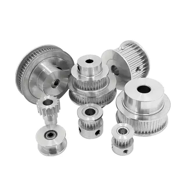
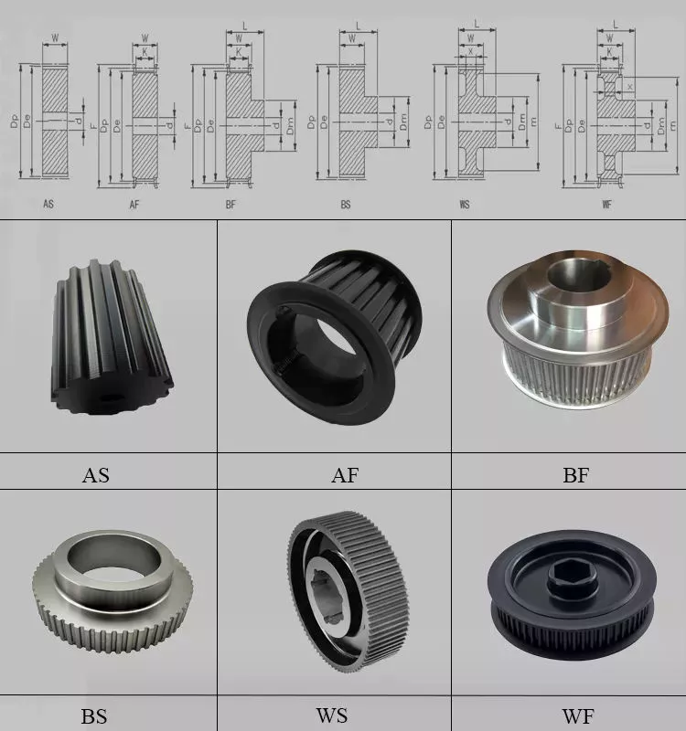
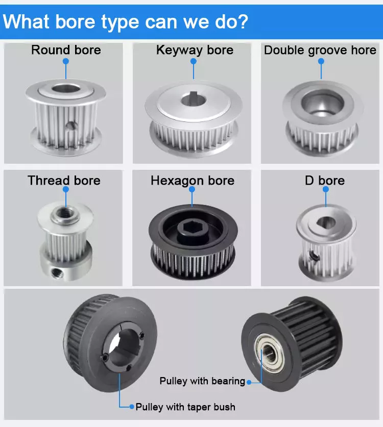
Three basic types of pulleys, their applications and ideal mechanical advantages

There are 3 basic types of pulleys: movable, fixed and compound. Each has its advantages and disadvantages, and you should be able to judge which type is best for your needs by looking at the table below. Once you have mastered the different types of pulleys, you can choose the right pulley for your next project. Now that you have mastered the 3 basic types, it is time to understand their applications and ideal mechanical advantages.
pulley

describe

The stress characteristics of a pulley depend on its size and construction. These stresses are derived by comparing the stress characteristics of different pulley designs. Stress criteria include static and fatigue strength analyses and specify maximum stress ranges. Stresses are calculated in a 3D stress field, including radial, tangential and axial stresses. The stress characteristics of pulleys are critical to the design and manufacture of industrial machines.
The principal stresses on the pulley shell are distributed in the tangential and hoop directions, close to the centerline of the pulley. If the pulley has a wide face, the axial stress occurring near the shell/disk junction can be large. The stress distribution was determined using British Standard BS5400 Part 10: Stresses at the shell and end disc connections for infinite fatigue life.
Another type of composite is a pulley with a belt section. Such structures are well known in the art. The corresponding help chapters for these elements contain detailed descriptions of the internal structure of these components. Chamfers between pulleys can also be defined using multiple tapers, with a smaller taper extending from midpoint 44 to large diameter 42. Additionally, the pulley can have multiple taper angles, and as the pulley moves away, the taper angle is from the center.

type

A pulley system uses a rope to move the object and 1 side of the rope to lift the load. The load is attached to 1 end of the pulley, while the other end can move freely in space. The force applied to the free end of the rope pulls the load up or down. Because of this, the mechanical advantage of the movable pulley is 2 to one. The greater the force applied to the free end of the rope, the greater the amount of movement achieved.
There are 3 common types of pulleys. The cast-iron variety has a rim at the front and a hub at the back. The arms of the pulley can be straight or curved. When the arms contract and yield instead of breaking, they are in tension. The top of the pulley centers the belt in motion and is available in widths ranging from 9mm to 300mm.
The rope, hub and axle are mounted on the pulley. They are common and versatile mechanical devices that make it easier to move or lift objects. Some pulleys change the direction of the force. Others change the magnitude. All types of pulleys can be used for a variety of different applications. Here are some examples. If you’re not sure which type to choose, you can find more resources online.
pulley

application

The applications for pulleys are almost limitless. This simple machine turns complex tasks into simple ones. They consist of a rope or chain wrapped around a wheel or axle. Using ropes, 1 can lift heavy objects without the enormous physical exertion of traditional lifting equipment. Some pulleys are equipped with rollers, which greatly magnifies the lifting force.
When used properly, the pulley system can change the direction of the applied force. It provides a mechanical advantage and allows the operator to remain separate from heavy objects. They are also inexpensive, easy to assemble, and require little lubrication after installation. Also, once installed, the pulley system requires little maintenance. They can even be used effortlessly. Despite having many moving parts, pulley systems do not require lubrication, making them a cost-effective alternative to mechanical lifts.
Pulleys are used in many applications including adjustable clotheslines in different machines, kitchen drawers and motor pulleys. Commercial users of pulley systems include cranes. These machines use a pulley system to lift and place heavy objects. They are also used by high-rise building washing companies. They can easily move a building without compromising its structural integrity. As a result, many industries rely on technology to make elevators easier.

Ideal mechanical advantage

The ideal mechanical advantage of a pulley system is the result of rope tension. The load is pulled to the center of the pulley, but the force is evenly distributed over the cable. Two pulleys will provide the mechanical advantage of 2 pulleys. The total energy used will remain the same. If multiple pulleys are used, friction between pulleys and pulleys reduces the return of energy.
Lever-based machines are simple devices that can work. These include levers, wheels and axles, screws, wedges and ramps. Their ability to work depends on their efficiency and mechanical superiority. The ideal mechanical advantage assumes perfect efficiency, while the actual mechanical advantage takes friction into account. The distance traveled by the load and the force applied are also factors in determining the ideal mechanical advantage of the pulley.
A simple pulley system has an MA of two. The weight attached to 1 end of the rope is called FA. Force FE and load FL are connected to the other end of the rope. The distance that the lifter pulls the rope must be twice or half the force required to lift the weight. The same goes for side-by-side pulley systems.

Materials used in manufacturing

While aluminum and plastic are the most common materials for making pulleys, there are other materials to choose from for your timing pulleys. Despite their different physical properties, they all offer similar benefits. Aluminum is dense and corrosion-resistant, and plastic is lightweight and durable. Stainless steel is resistant to stains and rust, but is expensive to maintain. For this reason, aluminum is a popular choice for heavy duty pulleys.
Metal can also be used to make pulleys. Aluminum pulleys are lightweight and strong, while other materials are not as durable. CZPT produces aluminium pulleys, but can also produce other materials or special finishes. The list below is just representative of some common materials and finishes. Many different materials are used, so you should discuss the best options for your application with your engineer.
Metals such as steel and aluminum are commonly used to make pulleys. These materials are relatively light and have a low coefficient of friction. Steel pulleys are also more durable than aluminum pulleys. For heavier applications, steel and aluminum are preferred, but consider weight limitations when selecting materials. For example, metal pulleys can be used in electric motors to transmit belt motion.
pulley

cost

Replacing a tensioner in a car’s engine can cost anywhere from $90 to $300, depending on the make and model of the car. Cost can also be affected by the complexity of the pulley system and how many pulleys are required. Replacement costs may also increase depending on the severity of the damage. The cost of replacing pulleys also varies from car to car, as different manufacturers use different engines and drivetrains.
Induction motors have been an industrial workhorse for 130 years, but their cost is growing. As energy costs rise and the cost of ownership increases, these motors will only get more expensive. New technologies are now available to increase efficiency, reduce costs and improve safety standards.
The average job cost to replace an idler varies from $125 to $321, including labor. Parts and labor to replace a car pulley can range from $30 to $178. Labor and parts can cost an additional $10 to $40, depending on the make and model of the car. But the labor is worth the money because these pulleys are a critical part of a car’s engine.

China wholesaler CZPT CZPT Machine Parts CZPT PAM Precision Correction Material KA-9898 K53050     with Free Design CustomChina wholesaler CZPT CZPT Machine Parts CZPT PAM Precision Correction Material KA-9898 K53050     with Free Design Custom

China high quality CNC Turning Machining Walnut Part CNC Machining Wooden Part wholesaler

Product Description

Product Description

1.Material:Aluminum Alloy,Stainless steeel,Carbon steel,Brass,Copper,Plastic,etc.
2. Size: Customized
3. Standard: DIN, ASTM, GB, JIS, ANSI, BS
4. Certification: ISO9001, SGS, CTI, ROHS,TS16949
 

Product Name Professional CNC machining parts ,CNC turning parts, Anodized aluminum parts
Surface Treatment Anodizing,Engraving,Polishing,Sand Blasting,Painting,Powder Coating,Silk Screening,Heat Treating,etc
Process Milling,Turning,Stamping,Drilling,Tapping,Knurling,Grinding,Laser-cutting, Bending,Mould injection
Surface Roughness Ra0.2–Ra3.2(Customized available as request)
Logo Service Support
Drawing Format 2D/(PDF/CAD) or 3D(IGES/STEP)

Product Processing
—————————–

CNC Milling Processing

1. Production machine: CNC machining center, CNC engraving machine, CNC drilling center(3axis,4axis,5axis)

2. Tolerance: +/-0.005mm

3. Surface roughness: Ra 0.4

4. Production machine origin

CNC Turning Processing

1. Production machine: CNC turning lathe, automatic lathe, turning-milling machine

2. Tolerance: +/-0.005mm

3. Surface roughness: Ra 0.4

4. Production machine origin


Sheet Metal Fabrication Processing

1. Production machine: Laser cutting machine,Punching machine, Bending machine

2. Tolerance: +/-0.1mm

3. Surface: Painted,powder coated,anodized,etc.

Wire EDM Cutting Processing

1.Production machine: WEDM-LS,WEDM-HS

2. Tolerance: +/-0.003mm

3. Surface roughness: Ra0.1

Product Show
———————

Our Workshop


Quality Inspection
Packing & Delivery

FAQ
Q: Are you trading company or manufacturer ?
A: We are factory.

Q: How long is your delivery time?
A: Generally it is 3-7days for sampels; bulk order 10-25days,depends on quantity and parts requirment.

Q: Do you provide samples ? is it free or extra ?
A: Yes,we could offer the sample and it will be charged according to the sample processing.

Q: What is your terms of payment ?
A: Payment600USD, 30% T/T in advance ,balance before shippment.

If you have another question, pls feel free to contact us.

How to Identify a Faulty Drive Shaft

The most common problems associated with automotive driveshafts include clicking and rubbing noises. While driving, the noise from the driver’s seat is often noticeable. An experienced auto mechanic can easily identify whether the sound is coming from both sides or from 1 side. If you notice any of these signs, it’s time to send your car in for a proper diagnosis. Here’s a guide to determining if your car’s driveshaft is faulty:
air-compressor

Symptoms of Driveshaft Failure

If you’re having trouble turning your car, it’s time to check your vehicle’s driveshaft. A bad driveshaft can limit the overall control of your car, and you should fix it as soon as possible to avoid further problems. Other symptoms of a propshaft failure include strange noises from under the vehicle and difficulty shifting gears. Squeaking from under the vehicle is another sign of a faulty driveshaft.
If your driveshaft fails, your car will stop. Although the engine will still run, the wheels will not turn. You may hear strange noises from under the vehicle, but this is a rare symptom of a propshaft failure. However, you will have plenty of time to fix the problem. If you don’t hear any noise, the problem is not affecting your vehicle’s ability to move.
The most obvious signs of a driveshaft failure are dull sounds, squeaks or vibrations. If the drive shaft is unbalanced, it is likely to damage the transmission. It will require a trailer to remove it from your vehicle. Apart from that, it can also affect your car’s performance and require repairs. So if you hear these signs in your car, be sure to have it checked by a mechanic right away.

Drive shaft assembly

When designing a propshaft, the design should be based on the torque required to drive the vehicle. When this torque is too high, it can cause irreversible failure of the drive shaft. Therefore, a good drive shaft design should have a long service life. Here are some tips to help you design a good driveshaft. Some of the main components of the driveshaft are listed below.
Snap Ring: The snap ring is a removable part that secures the bearing cup assembly in the yoke cross hole. It also has a groove for locating the snap ring. Spline: A spline is a patented tubular machined element with a series of ridges that fit into the grooves of the mating piece. The bearing cup assembly consists of a shaft and end fittings.
U-joint: U-joint is required due to the angular displacement between the T-shaped housing and the pinion. This angle is especially large in raised 4x4s. The design of the U-joint must guarantee a constant rotational speed. Proper driveshaft design must account for the difference in angular velocity between the shafts. The T-bracket and output shaft are attached to the bearing caps at both ends.
air-compressor

U-joint

Your vehicle has a set of U-joints on the driveshaft. If your vehicle needs to be replaced, you can do it yourself. You will need a hammer, ratchet and socket. In order to remove the U-joint, you must first remove the bearing cup. In some cases you will need to use a hammer to remove the bearing cup, you should be careful as you don’t want to damage the drive shaft. If you cannot remove the bearing cup, you can also use a vise to press it out.
There are 2 types of U-joints. One is held by a yoke and the other is held by a c-clamp. A full ring is safer and ideal for vehicles that are often used off-road. In some cases, a full circle can be used to repair a c-clamp u-joint.
In addition to excessive torque, extreme loads and improper lubrication are common causes of U-joint failure. The U-joint on the driveshaft can also be damaged if the engine is modified. If you are driving a vehicle with a heavily modified engine, it is not enough to replace the OE U-joint. In this case, it is important to take the time to properly lubricate these components as needed to keep them functional.

tube yoke

QU40866 Tube Yoke is a common replacement for damaged or damaged driveshaft tubes. They are desirably made of a metallic material, such as an aluminum alloy, and include a hollow portion with a lug structure at 1 end. Tube yokes can be manufactured using a variety of methods, including casting and forging. A common method involves drawing solid elements and machining them into the final shape. The resulting components are less expensive to produce, especially when compared to other forms.
The tube fork has a connection point to the driveshaft tube. The lug structure provides attachment points for the gimbal. Typically, the driveshaft tube is 5 inches in diameter and the lug structure is 4 inches in diameter. The lug structure also serves as a mounting point for the drive shaft. Once installed, Tube Yoke is easy to maintain. There are 2 types of lug structures: 1 is forged tube yoke and the other is welded.
Heavy-duty series drive shafts use bearing plates to secure the yoke to the U-joint. All other dimensions are secured with external snap rings. Yokes are usually machined to accept U-bolts. For some applications, grease fittings are used. This attachment is more suitable for off-road vehicles and performance vehicles.
air-compressor

end yoke

The end yoke of the drive shaft is an integral part of the drive train. Choosing a high-quality end yoke will help ensure long-term operation and prevent premature failure. Pat’s Driveline offers a complete line of automotive end yokes for power take-offs, differentials and auxiliary equipment. They can also measure your existing parts and provide you with high quality replacements.
A U-bolt is an industrial fastener with threaded legs. When used on a driveshaft, it provides greater stability in unstable terrain. You can purchase a U-bolt kit to secure the pinion carrier to the drive shaft. U-bolts also come with lock washers and nuts. Performance cars and off-road vehicles often use this type of attachment. But before you install it, you have to make sure the yoke is machined to accept it.
End yokes can be made of aluminum or steel and are designed to provide strength. It also offers special bolt styles for various applications. CZPT’s drivetrain is also stocked with a full line of automotive flange yokes. The company also produces custom flanged yokes for many popular brands. Since the company has a comprehensive line of replacement flange yokes, it can help you transform your drivetrain from non-serviceable to serviceable.

bushing

The first step in repairing or replacing an automotive driveshaft is to replace worn or damaged bushings. These bushings are located inside the drive shaft to provide a smooth, safe ride. The shaft rotates in a rubber sleeve. If a bushing needs to be replaced, you should first check the manual for recommendations. Some of these components may also need to be replaced, such as the clutch or swingarm.

China high quality CNC Turning Machining Walnut Part CNC Machining Wooden Part     wholesaler China high quality CNC Turning Machining Walnut Part CNC Machining Wooden Part     wholesaler

China manufacturer CZPT CZPT Tractor Truck CZPT CZPT Truck Spare Parts Cabin Parts Hinge Base Seat Original Quality Wg1642110016 Hinge Seat near me supplier

Product Description

Sinotruk CZPT Tractor Truck CZPT CZPT Truck Spare Parts Cabin Parts Hinge Base Seat Original Quality WgHinge Seat

FAQ:

Q1. What is your package of goods ?
A: Generally, we will pack the goods by Neutral boxes ,Pallets or Wooden boxes.  If any special needed ,please inform us earlier .

Q2. What the quality of your goods ?
A: We have different qualities, including Original, OEM, High copy, Copy, Refurbished and Second-hand. We can quote according to your real requirements and according to our experiences about your market requirements.

Q3,  How do you make a price offer and how long is the validity period??
A: Generally we quote prices according to goods’ part number , if you don’t have , please provide us chassis number , we can confirm the exactly goods according to the chassis number. About the inquiry list, we usually finish the quotation within 24 hours . If you are very urgent ,please inform us earlier. The prices are valid within 20 days.

 Q4. What is your terms of delivery?
A: EXW, FOB, CIF,CPT etc.

Q5. What is your terms of payment ?
A:  T/T, L/C ,D/P ,D/A and WESTER UNION. Normally 30% deposit, 70% balance payment before delivery. We’ll show you pictures of the goods to double confirm before you arrange balance payment.

Q6: Do you have warranty ?
Yes, of course . Our warranty its 3 month after installed in the truck.

 Q7. What is your delivery time?
A:  20GP normally 7 to 14 days , 40HC normally 13- 18 days after receiving prepayment. The exactly delivery time depends on the items and quantities which you ordered.
  
Q8. Can you make customized production according to samples?
A: Yes, we can produce according your samples or technical drawings. We can manufacture molds and fixtures.

Q9: whats your advantages ?
1.We have morethan15 years truck parts experiences. We can provide professional suggestions to customers.
2.Strict and complicated inspection process .
3.Perfect After-sales service.
4.Reply on time. 

Preventative Maintenance on Tractor Parts

You should not take your tractor out of commission by replacing the parts that are not working properly. You should be proactive about maintaining your tractor parts to ensure that they work well and are of the highest quality. You should also check if the company is 10 years old or more, as this will ensure that they have enough experience to handle warranty issues and any other problems. Lastly, you should check if the tractor parts company has a good reputation. Having a long standing company that is available around the clock is a plus.

agriculturalparts

Preventative maintenance of tractor parts

Performing preventative maintenance on tractor parts will help you avoid unexpected breakdowns and enhance its efficiency. Whether you’re the sole owner of a tractor or a part-owner, you should know which parts you need and where to find them. Having spares available is also important, as they can help you solve problems quickly. Listed below are some of the parts you need to know about. These components are essential for your tractor’s engine.

To maintain your tractor’s internal components, check for wear. Lubricate internal parts regularly to reduce friction. When possible, bring your tractor to a dealer for a thorough inspection. Additionally, remember to keep the tractor’s air filter clean. Dust in the air strains the tractor’s engine, and a dirty air filter can cause a lot of damage. By following the manufacturer’s instructions for proper maintenance, you can avoid costly repairs down the road.

For oil changes, check the owner’s manual for recommended oil change intervals. Make notes in the manual about the parts you’ll need. You can also refer to the manufacturer’s PM checklist. Depending on the type of tractor you own, you may need to change the oil once a year or more often. To keep your tractor running optimally, drain old oil after every use. The same goes for hydraulic fluid. Over time, it can become contaminated with particles and water. Therefore, it’s best to change it every year.

Modern tractors use a cooling system with fans and radiators. This system operates in varying temperatures and if it breaks down, you risk damaging the engine’s core parts. In addition, you should store your tractor’s battery under climate control. A battery maintainer can be purchased at any auto parts store. It’s a great idea to regularly inspect your tractor’s engine for problems as early as possible.

Types of tractor clutches

In a modern tractor, there are many types of transmission systems, and this article compares the pros and cons of each type. The original drive system of tractors relied on a clutch to change gears and range and engage/disengage the PTO drive. The clutch was usually a two-stage design; a full depression disengaged all drive systems while a partial depression only disengaged the gearbox. Today, these systems are independent.

The friction plate is a steel plate with a splined central hub. It features annular friction facings and is held between the flywheel and pressure plate. It has splines that limit its axial travel along the gearbox’s driving shaft and dampen torsional vibrations. Single-plate clutches are most commonly used in heavy agricultural equipment. While they were initially developed as a cost-effective alternative to drum brakes, they quickly gained popularity due to their low price and ease of use.

Another type of tractor clutch is the wrap-spring. These use a special cast-iron spring. This spring is able to transmit torque to the driven plate when the tractor is operating at normal engine speed, while the clutch springs help transmit torque to the driven plate when the engine is running at high engine speeds. The wrap-spring clutches must be lubricated with light oil and should be checked for deterioration after a few years.

The advantages and disadvantages of these types of clutches are explained briefly. They are generally made from high-quality materials and contain a high copper content. They have high-friction properties and can transfer heat effectively to the engine. The friction coefficient of these types of clutches ranges from 0.33 to 0.4. As a result, they are the best choice for intensive applications. In conclusion, there are many advantages and disadvantages of each type of tractor clutch.

agriculturalparts

Types of tractor transmission gears

There are several different types of tractor transmission gear. One of the most common is hydrostatic. A hydrostatic transmission works like a standard manual transmission, and operates with a pedal. To operate a hydrostatic transmission, you simply select the gear and engine speed you want, push the pedal, and the hydraulic oil turns the gears. Because this type of transmission is clutchless, it provides smooth forward/backward operation without the need for a manual shifter.

Tractor transmissions come in several types and have different features. Some of these systems are better for certain types of work than others, and you’ll find different types depending on the size and type of your tractor. Many tractors have 2 types of transmissions: geared speed and power shift. Each type offers different benefits, and they vary in cost and ease of use. There’s a geared speed transmission, a synchromesh transmission, and a power shift transmission.

A CVT (continuously variable transmission) is another popular option. Like hydro, CVTs use a belt to transfer power from the engine to the wheels. These tractors can shift gears with little effort. These tractors can reach up to 4 speeds without the need for a clutch. Powershift transmissions are simpler and more durable than CVTs. They’re also easier to repair. But a CVT may be the better choice for your farm tractor.

Hydrostatic and power shuttle transmissions allow you to shift gears and direction without the use of a clutch. Hydrostatic transmissions are usually hydraulically actuated, which makes it easy to change gears without using the clutch. Similarly, power shuttle transmissions are great for heavy-duty forward-and-reverse shifting. In either case, the clutches are hydraulically actuated and bathed in oil.

Types of CZPT fittings

In a nutshell, there are 2 types of CZPT fittings: standard and grease-fill. Standard CZPTs have 3 to 4 pumps of grease per fitting. Grease-filled CZPTs tend to attract dirt, dust, and sand, which can damage moving parts. Keeping these parts clean is crucial to their long-term performance. Using a rag to wipe off excess grease is an excellent way to ensure that the seals remain as sealed as possible.

There are different types of grease-filling tools available. Some are specifically designed to clear blocked CZPTs. These tools are used to fill the CZPT fitting with grease or diesel fuel and hit the fitting with a hammer. Be sure to use high-quality fitting rejuvenators, as cheap ones are less effective. These are also harder to find than grease-filling tools. To avoid these issues, use the proper tools when servicing your tractor.

CZPT fittings are used for many different kinds of tractor parts. You may find them on lawn equipment, construction equipment, and farming equipment. If you are unsure of what type your equipment has, ask your local CZPT dealer or visit 1 of their 17,000 CZPT AutoCare locations. Don’t forget to regularly grease these parts for the best performance. When you don’t have time to do so, they can lead to costly repairs.

Standard CZPTs feature a dome-shaped nipple that makes it easy to spot. Flow-stop fittings feature a ball check valve that reduces backflow during lubrication. Drive-type CZPTs feature a special coupler with a cross-pin to provide a positive lock. This type of grease CZPT eliminates the need for tapping during servicing.

agriculturalparts

Preventative maintenance of tractor’s CZPT fittings

Proper grease application and regular inspections are important parts of CZPT fittings. If a CZPT becomes stuck in an opening, the ball may not be able to come out. Lubrication around CZPTs is important as grease can damage the components and cause bigger problems. A tractor’s CZPT fittings are part of the tractor’s electrical system, so it is important to replace them when they become damaged.

Grease CZPTs allow the addition of grease at the manufacturer’s specifications. These fittings consist of a spring and metal ball inside a nipple. The grease gun compresses the spring and releases the ball from the nipple opening. Grease CZPTs are essential parts of heavy equipment, as a failed grease CZPT may cause brake failures and other systems to fail. Failure to maintain these fittings can cause rollover accidents.

Greasing the CZPTs is a vital part of regular tractor maintenance. Greasing the CZPTs will prevent your tractor’s bearings from sticking and make your work easier. Grease the CZPTs on pivot points and joints to keep them lubricated and running smoothly. For easy grease application, consider using a battery-powered grease gun. Once you have lubricated the CZPTs, you can move on to other parts of the tractor.

In addition to grease, you should check for leaks on your tractor’s CZPTs regularly. If you notice dirt buildup, there might be a leak. You can also check for any worn hoses to avoid major problems. If there is a leak, tighten the fittings and replace worn ones as soon as possible to avoid further damage. By performing these tasks regularly, you can increase the efficiency of your tractor and avoid unexpected breakdowns.

China manufacturer CZPT CZPT Tractor Truck CZPT CZPT Truck Spare Parts Cabin Parts Hinge Base Seat Original Quality Wg1642110016 Hinge Seat     near me supplier China manufacturer CZPT CZPT Tractor Truck CZPT CZPT Truck Spare Parts Cabin Parts Hinge Base Seat Original Quality Wg1642110016 Hinge Seat     near me supplier

China wholesaler Aerospace Rubber Parts Anti-Fungus Materials with high quality

Product Description

CUSTOMIZED PRODUCTS, WELCOME TO CONTACT AND CHAT

Product Name Aerospace Rubber Parts Anti-fungus Materials
Material NBR,EPDM,Silicone,HNBR;NR,EVA,FKM,SR.
Size Customized
Color Black, white or customized
Features Wear resistance; High temperature resistance; UV resistance
Applications for Kite; Plunger; Universal Rods
Certifications ISO9001; ISO14001; IATF16949; UL; CE; RoHS.
MOQ 1000 PCS
Samples Free samples are available
Delivery time 25-35 days after order is confirmed
Trading Term FOB, CIF, CFR, EXW etc.
Payment Term T/T, Western Union, Paypal etc.

Products Pictures:
 

HangZhousun’s Mold/Tooling

HangZhousun’s Workshop

About HangZhousun
 

HangZhousun Group
Total Number of Personnel:>350 staffs (as of June.24, 2571)
Total Production scale: >35000 square meters

Head Office: HangZhousun Rubber & Plastic Technology Co.,Ltd
Founded: 2002
Location: HangZhou, ZheJiang
Main Business: Compression Molding Rubber Products & Parts, etc.

Branch Company: HangZhou Mingrui Intelligent Technology Co., Ltd
Established: 2018
Location: HangZhou, ZheJiang
Main Business: Molds, Refined Hardware, Intelligent Automation Equipment, etc.

Branch Company: ZheJiang Yousheng New Material Technology Co.,Ltd
Established: 2018
Location: HangZhou, ZheJiang
Main Business: Extrusion Molding Rubber Products & Parts, etc.


R&D and Quality Control

HangZhousun’s R&D team has more than 120 staff ,and gathers CZPT and creative experts and professors.
Keeping responsibility in mind, R&D team brings multiple capabilities, supports HangZhousun keep leading at rubber&plastics industry.
R&D team forms strict management system on each project in compliance with latest world scientific standard and requirements.

We strictly emphasize on quality and management control.
Our R&D and production management follows TUV & IS014001 Environmental System.
Beyond these, Our finished products meet approval of ISO9001, IATF16949 & UL quality control system.
HangZhousun can make our products meet standards as customer’s demand like CE, ROHS, REACH, CP65, PAHS, FDA, TSCA,etc.

Overview of Different Types of Pulleys

A pulley is a wheel mounted on a shaft or shaft. Its purpose is to facilitate the movement or change of direction of the cable or taut rope, and to transmit power between the cable and the shaft. Pulleys are typically used for lifting, winding or forklift applications. If you are building your own pulley system, the following design and installation considerations should be followed. This article will give you an overview of the different types of pulleys.
pulley

Pulley System Mechanics

There are many different ways to utilize the mechanism of the pulley system. The most basic pulley system consists of a fixed wheel and a support frame. Both components are connected by ropes or cables used to support the load. A pulley system is effective when the force required to lift the load is less than the weight of the object being lifted.
One way to use a pulley system is to suspend a block with a mass of 0.80 kg on a fixed pulley. Then another person can hang a bucket weighing up to 40kg. The weight of the bucket is transferred to the fixed pulley. The rope is attached to the pulley by a loop or sling. The rope will spin and pull on the barrel or block.
The pulley system is also an important tool for lifting heavy objects. Pulleys are often used in construction equipment to make lifting heavy objects easier. Gun tackles, yard tackles, and stationary tackle systems are common examples of these devices. They use the mechanical advantage of the design to guide the force that lifts the object. If you want to learn more about pulley systems, visit Vedantu. This website will provide you with a full description of the mechanism and its application.

Types of pulleys

Many different types of pulleys are used to lift heavy objects. They change the direction of the force and are an integral part of the cable system. Therefore, pulleys can move large and heavy objects more easily. However, before buying a pulley, you should have an idea of ​​the benefits it brings. Below are some of the most common uses for pulleys.
Conical Pulley: Consists of several small conical pulleys connected to each other. The larger base of 1 pulley is used to guide the force. Round pulleys are used in the same way as step pulleys. They are widely used in industry and can be purchased at any hardware store. Pulleys are a huge investment, and the benefits they provide far outweigh the cost.
Movable Pulls: These are similar to their names, but work by allowing objects to move with the pull. Their movable parts are attached to the object to be lifted. They are also ideal for lifting heavy loads and can be found in utility elevators and construction cranes. They are also used in many other industries. They can also be made of wood, plastic or metal. The type of pulley you use depends on its intended use.

Mechanical Advantages of Pulley Systems

A pulley system is a simple machine that reduces the effort required to lift heavy loads. This mechanical advantage is proportional to the number of loops. For example, if you have a single rope loop, you must apply equal force to lift the weight. When you add another rope loop, you can lift heavier weights just by applying the same force. Therefore, a pulley system is an excellent way to use gravity to your advantage.
Mechanical advantage is a measure of the effectiveness of a pulley system. This ratio of force to work is called the mechanical advantage. In other words, if the rope system has a large mechanical advantage, it means that it requires less force to lift heavier loads. This advantage is usually measured in kilograms and is the same for all pulley systems. In general, the greater the mechanical advantage, the less effort is required to lift the load.
The mechanical advantage of a pulley system is that a single movable pulley requires half the force to lift an object than a single fixed pulley. Assuming frictionless bearings, the MA of a single pulley system is 2, similar to the MA of a single lever. A single pulley travels twice as much as it takes to move heavy objects manually.
pulley

Considerations when designing and installing a pulley system

The capacity of the pulley depends on the type and diameter of the cable. Besides its diameter, its sheath should also support it well. The basic function of the pulley is also important. However, most people tend to ignore the pulley selection process, resulting in ineffective load-pull capabilities. To avoid such problems, different parameters must be carefully considered during design and installation.
During the design and installation of the pulley system, the ratio of the cable diameter to the largest pulley diameter must be considered. Those who work in the industrial sector will have an idea of ​​this ratio. The greater the D:d ratio, the greater the capacity of the cable to withstand the load. The best way to ensure secure design is to take the right information and use it to design a system that is both robust and secure.
When designing a pulley system, it is important to remember that the pulley needs to have enough power to operate safely. In addition to horsepower, the belt should have sufficient elongation to absorb shock loads. If the elongation of the belt is very small, it is very likely that the teeth will be sheared or broken, causing serious damage to the system. Extensive belt sag should be compensated for by offsetting the driven pulley. Finally, the frame supporting the pulley should be rigid. Otherwise, the non-rigid frame will cause center distance and tooth skipping changes.

Add more pulleys to the system

Adding more pulleys to the spool might have some effect. The friction between the rope and the pulley increases with the number of pulleys, which in practice limits the number of spools. The best solution is to combine the pulleys into 1 housing. If the load is small enough, adding a few pulleys probably won’t make a difference.
Using multiple pulleys allows a single load to be lifted with half the force required. The longer the rope, the greater the mechanical advantage. In fact, a spool can withstand a load of 100 N. Additionally, adding more pulleys quadrupled the mechanical advantage. In this case, a single 100 N load would require a force of 25 Newtons.
When the rope is used, it stretches as the weight of the object increases. This will make the rope longer, increasing its length and increasing the distance over which the load can be lifted. Eventually, the rope will break and the lifted object will fall. Then you will have to buy a new rope. It may seem like an expensive proposition, but it pays off in the long run.

cast iron pulley

Cast iron pulleys are the most popular choice among industrial users. They are made of solid cast iron and usually cost very little. Their rims are held in place by a mesh that extends from a central boss. They also have spokes and arms that hold them in place. These pulleys are ideal for a variety of applications including fan belts, compressors and conveyors.
V-groove drive pulleys are ideal for general purpose pulleys. It has an inner diameter of 1 inch and is commonly used in feeders and ventilation curtain systems. Its steel straps prevent rust and ensure it meets or exceeds industry standards. 3-1/2″ cast iron pulleys are also available. In addition to the V-groove drive pulley, there are similar pulleys for power transmission. The V-groove drive pulley is powder coated for added durability.
The cross section of the arm is elliptical, with the long axis twice as long as the short axis. The radius of the arm is equal to the diameter of the pulley. The thickness of the arm is a key factor to consider when purchasing a pulley. If you’re not sure which material you need, you can always consider wooden or steel pulleys. They are lighter and have a higher coefficient of friction than metal pulleys.
pulley

timing pulley

Plastic timing pulleys have many advantages over steel timing pulleys. On the 1 hand, they are lightweight and corrosion resistant, making them ideal for applications that do not require high torque and tensile strength. Another benefit is their resistance to high temperatures. Plastic timing pulleys are ideal for applications involving flammable gases, solvents or particles. They can last for many years. For more information on the different types of plastic timing pulleys.
Vertical shaft drives require flanged timing pulleys. For large span drives, at least 1 of these pulleys must be flanged. The flange provides a secure connection to the shaft and prevents ratcheting of the timing belt. Finally, HTD timing belt teeth prevent timing belt ratcheting. These teeth need a large enough space to be seated. However, they can also cause a backlash. These pulleys are not suitable for applications where positional accuracy is critical.
Timing belt systems are designed to avoid such problems. The drive shaft and the driven shaft are aligned with each other. The pulleys are located on different planes and are connected by pitch lines. The pitch line of the timing pulley coincides with the pitch line of the belt. These pulleys are also easier to implement and maintain. It is better to use a synchronous system because the resulting gear system emits less noise than other systems.

China wholesaler Aerospace Rubber Parts Anti-Fungus Materials     with high qualityChina wholesaler Aerospace Rubber Parts Anti-Fungus Materials     with high quality

China Best Sales Customized Electric Coconut Tree Turntable Soft Play Game Equipment Indoor Playground Parts near me manufacturer

Product Description

Product Name Children indoor playground
Size According to customer’s area
Color customized
Theme Design

Jungle/Ocean, Candy, Pirate, Frozen Snowy, Volcano slide, or rainbow crochet 

Playground,etc.

Main Play games

Multientry 3 Lane Waving Slide, trampoline, flying fox, mouse hole climbing net, chain 

bridge, cannon gun, ball pool, punching bags, spiral slide, soft obstacles.

Features Exercise children’s drilling, climbing, jumping, running ability
Applicable areas

amusement parks, kindergartens, residential areas, supermarkets, schools, shopping 

centers, hotels, airports, hospitals, backyards, community parks and other children’s 

play centers

Material      1.Plastic parts: Imported LLDPE

2.Structure Frame: inner by Φ48mm, thickness 1.5mm/ 1.8mm round, hot-galvanized 

steel pipes,covered by quality PVC foam padding 

3.Soft parts: inner by laminated wood, middle by EPE, the high-pressure polyethylene 

foam, outmost layer by phthalate-free & eco-friendly colorful PVC fabric

4. Outer cover: Soft Covering PVC

5. Flooring: quality interlocking EVA foam mats /PVC carton tiles/ interlocking ABS floor

mat/artificial grasses

6. Safety net: square/diamond fireproof ropes and nets, muliple color for choice.
Advantage     1. Anti-UV
2. Anti-static
3.Security
4.Environmental protection
5.Color is not easy to fade
Age range 2-12 years
Capacity 15-50 people
Delivery time 7-15 days
Packing cotton plastic film, carton, woven bag
Installation Professional and useful CAD instruction, engineer can come to install
Using life 5-7 years
Quality High temperature resistant cold and edge protection
Special Service Free design according to your area size and requirement.
Certificate CE, SGS, TUV, ASTM, IS9001 certificates.


Product Project


Our company

Certification

Packing & Shipping

FAQ:
Q1: Are you a factory or trading company

   A1: We are a factory, we can guarantee our price is first-hand, very cheap and competitive.


   Q2: How does your factory do regarding quality control?

   A2: All the products will be 100% checked before the shipment.


   Q3: When can I get the price?

   A3:Usually we quote within 24 hours after we get your inquiry.


   Q4: How could I get a sample?

   A4: if you can not buy our product in your local area, we will ship a sample to you.You will be    charged a sample price plus all related shipping costs.Express delivery charge depends on the      quantity of the samples.


   Q5: What is the price of shipping?

   A5: Depending upon the port of delivery, prices varies.
 

More products


Benefits and Uses of Miter Gears

If you’ve ever looked into the differences between miter gears, you’re probably wondering how to choose between a Straight toothed and Hypoid one. Before you decide, however, make sure you know about backlash and what it means. Backlash is the difference between the addendum and dedendum, and it prevents jamming of the gears, protects the mating gear surfaces, and allows for thermal expansion during operation.
gear

Spiral bevel gears

Spiral bevel gears are designed to increase efficiency and reduce cost. The spiral shape creates a profile in which the teeth are cut with a slight curve along their length, making them an excellent choice for heavy-duty applications. Spiral bevel gears are also hypoid gears, with no offsets. Their smaller size means that they are more compact than other types of right-angle gears, and they are much quieter than other types of gear.
Spiral bevel gears feature helical teeth arranged in a 90-degree angle. The design features a slight curve to the teeth, which reduces backlash while increasing flexibility. Because they have no offsets, they won’t slip during operation. Spiral bevel gears also have less backlash, making them an excellent choice for high-speed applications. They are also carefully spaced to distribute lubricant over a larger area. They are also very accurate and have a locknut design that prevents them from moving out of alignment.
In addition to the geometric design of bevel gears, CZPT can produce 3D models of spiral bevel gears. This software has gained widespread attention from many companies around the world. In fact, CZPT, a major manufacturer of 5-axis milling machines, recently machined a prototype using a spiral bevel gear model. These results prove that spiral bevel gears can be used in a variety of applications, ranging from precision machining to industrial automation.
Spiral bevel gears are also commonly known as hypoid gears. Hypoid gears differ from spiral bevel gears in that their pitch surface is not at the center of the meshing gear. The benefit of this gear design is that it can handle large loads while maintaining its unique features. They also produce less heat than their bevel counterparts, which can affect the efficiency of nearby components.

Straight toothed miter gears

Miter gears are bevel gears that have a pitch angle of 90 degrees. Their gear ratio is 1:1. Miter gears come in straight and spiral tooth varieties and are available in both commercial and high precision grades. They are a versatile tool for any mechanical application. Below are some benefits and uses of miter gears. A simple explanation of the basic principle of this gear type is given. Read on for more details.
When selecting a miter gear, it is important to choose the right material. Hard faced, high carbon steel is appropriate for applications requiring high load, while nylon and injection molding resins are suitable for lower loads. If a particular gear becomes damaged, it’s advisable to replace the entire set, as they are closely linked in shape. The same goes for spiral-cut miter gears. These geared products should be replaced together for proper operation.
Straight bevel gears are the easiest to manufacture. The earliest method was using an indexing head on a planer. Modern manufacturing methods, such as the Revacycle and Coniflex systems, made the process more efficient. CZPT utilizes these newer manufacturing methods and patented them. However, the traditional straight bevel is still the most common and widely used type. It is the simplest to manufacture and is the cheapest type.
SDP/Si is a popular supplier of high-precision gears. The company produces custom miter gears, as well as standard bevel gears. They also offer black oxide and ground bore and tooth surfaces. These gears can be used for many industrial and mechanical applications. They are available in moderate quantities from stock and in partial sizes upon request. There are also different sizes available for specialized applications.
gear

Hypoid bevel gears

The advantages of using Hypoid bevel and helical gears are obvious. Their high speed, low noise, and long life make them ideal for use in motor vehicles. This type of gear is also becoming increasingly popular in the power transmission and motion control industries. Compared to standard bevel and helical gears, they have a higher capacity for torque and can handle high loads with less noise.
Geometrical dimensioning of bevel/hypoid bevel gears is essential to meet ANSI/AGMA/ISO standards. This article examines a few ways to dimension hypoid bevel and helical gears. First, it discusses the limitations of the common datum surface when dimensioning bevel/helical gear pairs. A straight line can’t be parallel to the flanks of both the gear and the pinion, which is necessary to determine “normal backlash.”
Second, hypoid and helical gears have the same angular pitch, which makes the manufacturing process easier. Hypoid bevel gears are usually made of 2 gears with equal angular pitches. Then, they are assembled to match 1 another. This reduces noise and vibration, and increases power density. It is recommended to follow the standard and avoid using gears that have mismatched angular pitches.
Third, hypoid and helical gears differ in the shape of the teeth. They are different from standard gears because the teeth are more elongated. They are similar in appearance to spiral bevel gears and worm gears, but differ in geometry. While helical gears are symmetrical, hypoid bevel gears are non-conical. As a result, they can produce higher gear ratios and torque.

Crown bevel gears

The geometrical design of bevel gears is extremely complex. The relative contact position and flank form deviations affect both the paired gear geometry and the tooth bearing. In addition, paired gears are also subject to process-linked deviations that affect the tooth bearing and backlash. These characteristics require the use of narrow tolerance fields to avoid quality issues and production costs. The relative position of a miter gear depends on the operating parameters, such as the load and speed.
When selecting a crown bevel gear for a miter-gear system, it is important to choose 1 with the right tooth shape. The teeth of a crown-bevel gear can differ greatly in shape. The radial pitch and diametral pitch cone angles are the most common. The tooth cone angle, or “zerol” angle, is the other important parameter. Crown bevel gears have a wide range of tooth pitches, from flat to spiral.
Crown bevel gears for miter gear are made of high-quality materials. In addition to metal, they can be made of plastic or pre-hardened alloys. The latter are preferred as the material is less expensive and more flexible than steel. Furthermore, crown bevel gears for miter gears are extremely durable, and can withstand extreme conditions. They are often used to replace existing gears that are damaged or worn.
When selecting a crown bevel gear for a miter gear, it is important to know how they relate to each other. This is because the crown bevel gears have a 1:1 speed ratio with a pinion. The same is true for miter gears. When comparing crown bevel gears for miter gears, be sure to understand the radii of the pinion and the ring on the pinion.
gear

Shaft angle requirements for miter gears

Miter gears are used to transmit motion between intersecting shafts at a right angle. Their tooth profile is shaped like the mitre hat worn by a Catholic bishop. Their pitch and number of teeth are also identical. Shaft angle requirements vary depending on the type of application. If the application is for power transmission, miter gears are often used in a differential arrangement. If you’re installing miter gears for power transmission, you should know the mounting angle requirements.
Shaft angle requirements for miter gears vary by design. The most common arrangement is perpendicular, but the axes can be angled to almost any angle. Miter gears are also known for their high precision and high strength. Their helix angles are less than 10 degrees. Because the shaft angle requirements for miter gears vary, you should know which type of shaft angle you require before ordering.
To determine the right pitch cone angle, first determine the shaft of the gear you’re designing. This angle is called the pitch cone angle. The angle should be at least 90 degrees for the gear and the pinion. The shaft bearings must also be capable of bearing significant forces. Miter gears must be supported by bearings that can withstand significant forces. Shaft angle requirements for miter gears vary from application to application.
For industrial use, miter gears are usually made of plain carbon steel or alloy steel. Some materials are more durable than others and can withstand higher speeds. For commercial use, noise limitations may be important. The gears may be exposed to harsh environments or heavy machine loads. Some types of gears function with teeth missing. But be sure to know the shaft angle requirements for miter gears before you order one.

China Best Sales Customized Electric Coconut Tree Turntable Soft Play Game Equipment Indoor Playground Parts     near me manufacturer China Best Sales Customized Electric Coconut Tree Turntable Soft Play Game Equipment Indoor Playground Parts     near me manufacturer

China Good quality China Green Prefilter for Bissell Pet Hair Eraser Hand Vacuum Cleaners Replace Part 1608653 & 1608654 with Great quality

Product Description

Basic Specifications:
 

Part Name             Green Pre Filters for Bissell Pet Hair Eraser Hand Vacuum Cleaners Replace Part 1608653 & 1608654
To Fit  For Bissell Pet Hair Eraser Hand Vacuum Cleaners Replace Part 1608653 & 1608654
Sizes  Size of Filter:111x100x70mm
 Size of Outer Cover:Top Diameter:68mm Bottom Diameter:78mm High:61mm
Colour   Green and White (Customized)
Structures  Plastic Frame and PET
Filtering Efficiency Grade  Pre Efficiency (Customized)
Special Properties  Removes Existence of Dust Mites, Mold Spores, Pollen and PET Dander Inside Your Home.

  
Other information:
 

Transport Package Poly bag or Box in Carton
Certification ISO9001,ISO14001,ROHS
Delivery Time 25days after the payment arrives for a 40ft.
Payment Terms T/T,L/C at sight, Paypal, Western Union and so on.
Inspection: We accept 100% inspection, welcome to our factory for inspection.
Quality guarantee: 12 months
shipment By air,By express,LCL and FCL by sea. according the Qty and your demand.


Product show:


When your axle needs to be replaced

If you’re wondering when your axle needs to be replaced, you should be aware of these signs first. A damaged axle is usually a sign that your car is out of balance. To tell if the axle needs to be replaced, listen for the strange noise the wheels make as they move. A rhythmic popping sound when you hit bumps or turns indicates that your axle needs to be replaced. If this sounds familiar, you should visit a mechanic.
Driveshaft

Symptoms of a broken shaft

You may notice a clicking or clanking sound from the rear of the vehicle. The vibrations you feel while driving may also indicate damaged axles. In severe cases, your car may lose control, resulting in a crash. If you experience these symptoms, it’s time to visit your auto repair shop. For just a few hundred dollars, you can get your car back on the road, and you don’t have to worry about driving.
Often, damaged axles can be caused by a variety of causes, including poor shock or load bearing bearings. Other causes of axle problems can be an overloaded vehicle, potholes, or a car accident. A bad axle can also cause vibrations and power transmission failures while driving. A damaged axle can also be the result of hitting a curb or pothole. When shaft damage is the cause of these symptoms, it must be repaired immediately.
If your car’s front axle is bent, you may need to replace them at the same time. In this case, you need to remove all tires from the car, separate the driveshaft from the transmission, and remove the axle. Be sure to double check the alignment to make sure everything is ok. Your insurance may cover the cost of repairs, but you may need to pay a deductible before getting coverage.
Axle damage is a common cause of vehicle instability. Axles are key components of a car that transmit power from the engine to the wheels. If it breaks, your vehicle will not be able to drive without a working axle. Symptoms of damaged axles can include high-speed vibrations or crashes that can shake the entire car. When it breaks down, your vehicle won’t be able to carry the weight of your vehicle, so it’s important to get your car repaired as soon as possible.
When your axle is damaged, the wheels will not turn properly, causing the vehicle to crash. When your car has these problems, the brakes won’t work properly and can make your car unstable. The wheels also won’t line up properly, which can cause the brakes to fail. Also, a damaged axle can cause the brakes to become sluggish and sensitive. In addition to the obvious signs, you can also experience the sound of metal rubbing against metal.

Types of car axles

When you’re shopping for a new or used car, it’s important to know that there are different types of axles. Knowing the year, make, model, trim and body type will help you determine the type you need. For easy purchasing, you can also visit My Auto Shop and fill out the vehicle information checklist. You can also read about drivetrains and braking systems. After mastering the basic information of the vehicle, you can purchase the axle assembly.
There are 2 basic types of automotive axles: short axles and drive axles. The axle is the suspension system of the vehicle. They carry the drive torque of the engine and distribute the weight throughout the vehicle. While short shafts have the advantage of simpler maintenance, dead shafts are more difficult to repair. They’re also less flexible, which means they need to be durable enough to withstand harsh conditions.
Axles can be 1 of 3 basic types, depending on the weight and required force. Semi-floating shafts have a bearing in the sleeve. They attach to the wheel and spin to generate torque. Semi-pontoons are common in light pickup trucks and medium-duty vehicles. They are not as effective as floating axles, but still provide a solid foundation for wheel alignment. To keep the wheels aligned, these axles are an important part of the car.
The front axle is the largest of the 3 and can handle road shocks. It consists of 4 main parts: stub shaft, beam, universal pin and track rod. The front axle is also very important as it helps with steering and handling road shocks. The front axle should be strong and durable, as the front axle is most susceptible to road shocks.
Cars use 2 types of axles: live and dead. Live axles connect to the wheels and drive the vehicle. Dead axles do not drive the wheels and support the vehicle. Those with 2 wheels have live axles. Heavy trucks and trailers use 3 or more. The number of axles varies according to the weight and load of the vehicle. This will affect which type of axle you need.
Driveshaft

life expectancy

There are a few things to keep in mind when determining the life expectancy of an automotive axle. First, you should check for any signs of wear. A common sign is rust. If your vehicle is often driven in snow and ice, you may need to replace the axle. Also, you should listen for strange sounds from the wheels, such as rhythmic thumping.
Depending on the type of axle, your car may have an average lifespan of 70,000 miles. However, if you have an older car, the CV axles probably won’t last 5 years. In this case, you may wish to postpone the inspection. This way, you can save money on repairs. However, the next step is to replace the faulty CV shaft. This process can take anywhere from 1 hour to 3 hours.
Weaker axles will eventually break. If it were weakened, it would compromise the steering suspension, putting other road users at risk. Fortunately, proper maintenance will help extend the life of your axle. Here are some tips for extending its lifespan. A good rule of thumb is to never go over speed bumps. This will cause sudden breakage, possibly resulting in a car accident. To prolong the life of your vehicle’s axles, follow these tips.
Another thing to check is the CV connector. If loose, it can cause vibration or even breakage if not controlled. Loose axles can damage the body, suspension and differential. To make matters worse, the guard on the CV joint could tear prematurely, causing the shaft to come loose. Poor CV connections can damage the differential or transmission if left unchecked. So if you want to maximize the life expectancy of your car’s axles, consider getting them serviced as soon as possible.
Driveshaft

The cost of repairing a damaged axle

A damaged axle may need repair as it is responsible for transferring power from the engine to the wheels. A damaged axle can cause a crash or even loss of control. Repairing an axle is much simpler than dealing with an accident. However, damaged axles can cost hundreds of dollars or more. Therefore, it is important to know what to do if you suspect that your axle may have a damaged component.
When your car needs to be replaced or repaired, you should seek the help of a professional mechanic to keep your car safe. You can save a lot of money by contacting a local mechanic who will provide the parts and labor needed to repair the axle. Also, you can avoid accidents by fixing your car as soon as possible. While axles can be expensive, they can last for many years.
The cost of repairing a damaged axle depends on the amount of repairs required and the vehicle you are driving. Prices range from $300 to $1,000, depending on the car and its age. In most cases, it will cost you less than $200 if you know how to fix a damaged axle. For those without DIY auto repair experience, a new axle can cost as little as $500. A damaged axle is a dangerous part of driving.
Fortunately, there are several affordable ways to repair damaged axles. Choosing a mechanic who specializes in this type of repair is critical. They will assess the damage and decide whether to replace or repair the part. In addition to this, they will also road test your car after completing the repairs. If you are unsure about repair procedures or costs, call a mechanic.

China Good quality China Green Prefilter for Bissell Pet Hair Eraser Hand Vacuum Cleaners Replace Part 1608653 & 1608654     with Great qualityChina Good quality China Green Prefilter for Bissell Pet Hair Eraser Hand Vacuum Cleaners Replace Part 1608653 & 1608654     with Great quality