Author Archives: ep

China OEM Customed Tractor Forging Parts/Small Part Forging/Forged Part with High Quality with Hot selling

Product Description

A&T Industry is a contract manufacture and exporter of high quality  forging parts with more than 13 years experience.

Customized available when get drawing or sample.


1.customized cnc machining part 
2.OEM & ODM by customer design 
3. Good appearance working 
4. Complex CNC Parts
 

1.OEM & ODM by customer design
2.Product picture shown here just for reference, we never sell them to other customers
3.Custom-made according to customer’s drawings
4. Factory custom manufacture hight precision turning part


Material  Steel, Zinc, Alunumin, Brass.Stainless steel.
Surface treatment Nickel plating. Zinc plating, Chrome plating, Oxidation. Anodization
Tolerance +/-0.01mm or +/- 0.0004″
Thread Standard NPT,BSP(G),M, GHT,UN,NPSM,BSPT(Tr),NPTF…    
Quality control 100% inspection on critical dimensions
Inspection equipment Three axis meansuring machine for X.Y.Z. Projection meter.
Production output 100000.000 pieces/ month
Productin range Part ID from 2-500mm with tolerance +/-0.01mm                                     
Experience 12 years of professional  OEM service
Supply chain process PPAP
Ability To develop hundreds of new parts annually.                               
 Packaging  Standard export carton with palletized
 Lead time 35 days regularly 
 Term of Payment  T/T. L/C or Customer’s request

 
ABOUT US:

A&T Industry is a contract manufacture and exporter of quality sand castings,
investment castings, lost foam castings, hot forgings, cold forgings, stampings, 
machined parts, injectionmolded plastics parts, etc.

We are a dedicated team of customer focused industry professionals with 
extensive experience in manufacturing,  materials engineering, 
quality assurance, logistics management  and inventory control.

We utilize our experience and sources advantage to provide our customers 
with cost effective and value based solutions to meet their engineering and 
design needs while exceeding their quality and procurement requirements.

A&T Industry is located in HangZhou, a major seaport, Olympic Host City and 
industrial center of China. 

Assurance,

 100% quality manufacturing.
 We guarantee that our products meet your supplied specifications
 Extremely competitive pricing
 Delivery to your port or front door
 4 —- 8 week lead times
 We handle all paperwork
 Partial container orders
 Flexible payment options
 Unique tooling options
 Full range of packaging options from bulk to retail ready
 Complete testing services available

FAQs

1. Where is your location?

We are located in HangZhou City of China and are closed to Airport. It takes 30minuts by car from Liuting Airport our company.

2. How long has the company been established?

AT INDUSTRY was established in 2009. There is 6 years exporting experiences.

3. How many employees do you have?

Administration / sales    4
Engineering / design as our partner     8
Production as our partners 120
Quality assurance / inspection   10

4. Which countries do you export to?

U.S.A, Germany, France, Italy, UK, Brazil, Middle east of Asia, Thailand, 

5. What proportion of your goods are exported?

100% of our production are exported to all over the world.

6. How long does it take to receive samples?

a) Pattern:30-45days after order 
b) Sample:30days after pattern finishing.
c) The lead time is the general production period and does not include the transportation time.

7. New product development process

Got tooling order and sample order with 50% deposit—Hold a meeting with the relation dept. to ensure the developing schedule—Design pattern, fixture and gauge and making them in our house—mold steel buying—Machining—Inspection—Send out the sample with initial inspection report.

8. How long is the manufacturing lead time?

Mass Production: 90days after sample approval by yours.
The lead time is the general production period including the transportation time.
We could make some special production arrangement effectively if customer has urgent need.

9. What basis can we buy goods?

We generally offer customers prices FOB& CIF (Carriage, Insurance & Freight). The CIF includes the freight cost to your nominated sea port.
We do provide clearance of goods which needs to be handled by a local freight forwarder.
All local costs and taxes are the responsibility of the buyer. We are happy to offer advisement on shipping if required. 

10. What are the payment terms?

Payment terms are negotiable and will improve for long term customers.
During the initial stages, we request 50% of tooling fee in advance with the balance payable on acceptance of samples.
Production orders can be negotiable. We prefer 50% deposit and the balance by T/T before sails. But sometimes T/T 30 days after sails would also acceptable. 

11. Which currency can we buy in?

We can deal in USD / Euro currency / GBP.

12. How long does it take to ship goods from China by sea?

It takes about 5 weeks to European ports plus 1 week customs clearance, so you can get the container within 6 to 7 weeks. It takes about 2 weeks to east coast and 3 weeks to west coast US ports. All sea goods are shipped from HangZhou Port. 

13. How long does it take to ship goods from China by air?

It takes about 7 days to all major destinations. 

14. Can we visit the factory to conduct an audit?

Yes, you are welcome to visit our partner factory by prior agreement. 

15. How do we retain client confidentiality?

We are happy to sign Confidentiality Agreements with customers and will honor them.

16. Which languages do we do business in?

Although we do business with many countries around the world, we can only communicate effectively in Chinese English.
All information supplied should therefore be supplied in this form. 

17. Is there a minimum volume of business required to conduct international purchasing?

There are no minimum volumes, but the prices of the goods, plus the fixed costs of importing makes it more economical to buy in high volumes. All potential customers will be assessed on an individual basis to determine if it appears a viable option for all parties to develop a relationship. 

18. What type of parts you are specialized in?

Our business contains 2 areas, 
one is for construction precast including lifting system, rigging hardware metal parts. 
 
Another is customized metal business of quality sand castings, investment castings, lost foam castings, hot forgings, cold forgings, stampings, machined parts, injectionmolded plastics parts, etc. 

19. Which kind of equipments do you have?

Forging friction press 160Ton, 300Ton, 630Ton, 1200Ton
Casting CZPT of 200kg, 500kg,1000kgs, 2000kgs
Press of 63ton, 120tons
CNC Machining center
CNC Vertical Lathe
CNC Lathe center
Boring machine
Drilling machine


Proper Maintenance of Tractor Parts

Proper maintenance of tractor parts is a necessity if you want to keep them running smoothly. Here are some things to keep in mind:
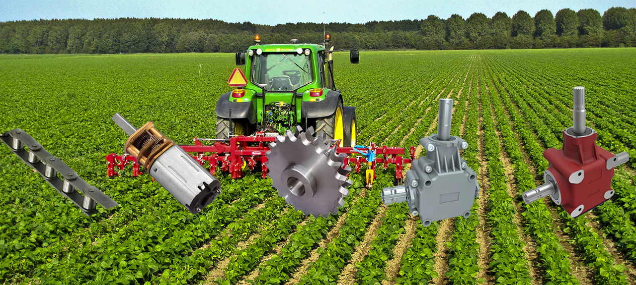
agriculturalparts

Proper maintenance of tractor parts

To ensure that your tractor is operating at peak efficiency, you should perform preventative maintenance on its various parts. Before opening the cab of your tractor, perform a visual inspection to check for any problems. Look for leaking fluids, hoses, and cables. Tighten loose connections, and clean any debris from these components. Also check the sediment bowl under the fuel filter for any material or water. If the sediment bowl has a large amount of material, it may be time to replace the fuel filter or the air filter.

Despite the monetary cost of maintaining your tractor, a few simple things can keep your investment in top condition. For instance, lubrication can prevent corrosion and friction, while cleaning air filters can extend their useful life. The paint on your tractor should also be inspected regularly. Regular lubrication will help you avoid expensive repairs, and will also increase efficiency. Proper maintenance of tractor parts can also help you prevent heavy rust.

Checking your tractor’s internal parts regularly can prevent big problems from crop failures. Lubricating internal parts helps reduce friction, and you should also replace blown or broken bulbs and exhaust fluid. Regular maintenance at tractor dealers will help prevent potential problems. A dealer will also perform tune-ups and oil changes for you, reducing the chances of unexpected issues. For those who don’t have the time to perform the maintenance themselves, consider visiting a tractor dealership.

In addition to inspecting engine components, you should also regularly check your tractor’s hydraulic system. Make sure that the fluids are in good condition, as rust, internal damage, and engine clogs can be caused by dirty or leaking hydraulic hoses. As with any mechanical system, the engine is the heart of a tractor, so it’s vital to maintain the oil tank as often as possible. For these checks, you can use a reference to your tractor model before purchasing new parts.

To extend the life of tractor parts, owners should regularly change the oil in the engine. This is necessary to prevent wear and tear on the tractor parts. Proper oil changes also increase the resale value of the equipment and extend its performance. You can use a grease gun to freshen up the grease nipples, which prevents the rusting of moving parts. By following these tips, you can make sure that your tractor runs smoothly.
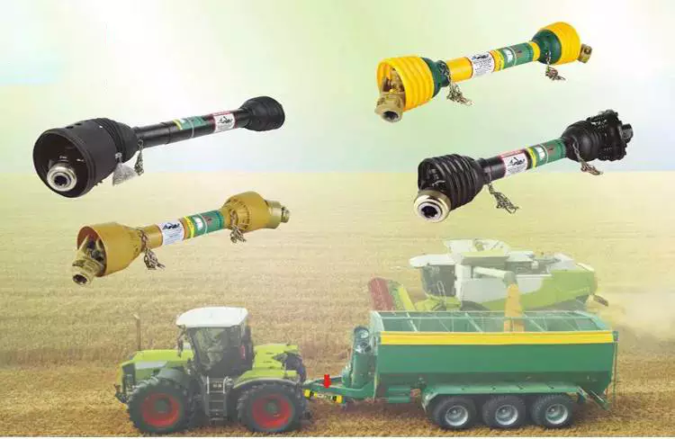
agriculturalparts

Preventative maintenance

Performing preventative maintenance on your tractor is an important way to maintain your machine and minimize the risk of unexpected breakdowns. It is an essential part of tractor ownership because regular maintenance reduces the risk of costly repairs. Before you begin a tractor maintenance program, read the manual to determine what common maintenance items are needed for the specific model. This will help you keep the parts in good shape and save you money in the long run.

Proper checkups on engine fluids, radiator fluid and transmission fluid are essential for maintaining the efficiency of your equipment. It’s important to refill these tanks with clean fluids to avoid rust, internal damage, and engine clogs. The following preventative maintenance tasks are recommended by tractor manufacturers:

Check tire pressure and inflation, as well as inspect the rims and lug nuts. Then, check the axles and drive shafts to ensure they are in good condition. Replace any damaged or missing lug nuts. And lastly, check all lights. Make sure all bulbs are functioning and replaced if necessary. To prevent unnecessary breakdowns, follow these tips to maximize the performance of your tractor. You will be glad you did.

If you have a spare part, be sure to have it on hand. Having a spare part handy will make it easier to do preventative maintenance on your tractor and save you the hassle of calling a repair shop or waiting for the parts to arrive. If you’re looking to get the best value for your money, proactive tractor maintenance is essential. In addition to routine inspections, remember to keep the tractor running at its peak performance level. You may want to have a checkup performed every 6 months or so.

Operator training is another essential preventive maintenance step. Operators must know how to perform routine maintenance tasks without fail. Operator training can be as simple as a review of the operator’s manual and demonstrating how systems and controls work. Training can also involve training operators on how to use checklists to make sure that all minor maintenance steps are performed correctly. This can save you thousands of dollars in repairs. Also, by performing regular preventative maintenance, you can avoid unexpected breakdowns.
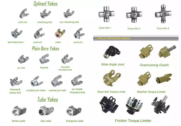
agriculturalparts

Types of filters

A tractor’s air filter, for instance, should be changed on a regular basis to keep the engine performing at peak performance. The reason is that working tractors are constantly exposed to debris and other substances in the driving environment. Even show tractors should periodically check their air filters to ensure they are functioning properly. A single chunk of dust can cause problems inside the sensitive machinery. That is why it’s important to replace filters at the appropriate intervals.

There are several different types of filters on a tractor. The type of filter needed depends on the original reference and the manufacturer. Listed below are some of the most common types of filters used by tractors. Agricolors’ website lets you choose the model of your tractor and then offers the corresponding filter made by the original manufacturer. Alternatively, you can choose an adaptable filter of equivalent quality. These filters are designed to fit various types of tractors, ranging from lawnmowers to combines.

Oil, air, and hydraulic filters are essential for tractor parts. Those with oil filters protect hydraulic components from harmful impurities. Fuel filters protect the injector pump from damage caused by debris. If your tractor doesn’t have filters, you’ll experience a variety of problems. You’ll notice odd noises or reduced HP. Or you might smell fuel when the engine starts. If these symptoms sound familiar, it’s a problem with your filters.

Tractor oil filter replaces itself every few months or so. Tractor oil coagulates over time into black globs. If not replaced, the globs clog up engine parts. Tractor oil filter acts like the kidneys and liver of the tractor, filtering brackish globs out of your engine. Like the human body, a tractor’s filters have similar functions to the human body’s. When they stop working properly, your tractor’s engine will no longer function optimally.

China OEM Customed Tractor Forging Parts/Small Part Forging/Forged Part with High Quality     with Hot sellingChina OEM Customed Tractor Forging Parts/Small Part Forging/Forged Part with High Quality     with Hot selling

China supplier BMX Bike Tractor Agricultural Machine Lock Pin Casting Stainless Steel Parts with Great quality

Product Description

1. We specialize in manufacturing kinds of metal stamping parts and machined parts etc since 1993 with ISO9001 management.


Product detail info

Material range


Carbon steel, alloy steel , stainless steel, aluminum alloy; brass alloy; tinplate, copper , Aluminum Alloy, Zink Alloy, Copper Alloy ect.

 Surface

Zinc plating, chrome plating, black treatment, anodize, powder coating, polishment, brass plating, etc.


Machining

processes

Turning, bending, drilling, threading, milling etc according to the parts requiement with advanced machines

 Equipment

Turning machines, bending machines, treader, mills, CNC, machining center, etc.

Service

OEM & ODM

Thickness of the material

0.5mm ~12mm, or other special requirment

Standard

ANSI. API. BS. DIN. JIS. GB. Etc.

Application   range

Power accessories


Building accessories

Auto Parts

Line fitting

Construction machinery parts


Any interests in our products, please feel free to contact us.

About Us:

Founded in 1993, CZPT Metal Products Co., Ltd. is a professional manufacturer and supplier of custom metal products in China. We endearors to be perfect on quality, service, competitive and responsibility. Today, you can see our products everywhere in the world.

We make OEM stamping parts, deep drawn parts, welding products, machined & CNC & turning & drilling & threading proudcts.All products surface treatment can be done according to customer’ requirement.

We treasure each and every possible opportunity and see every customer’s satisfaction as our goal. Give us a call today, our engineers will answer any of your questions in 24-48 hours.

Main Products:

Stamping Parts, Welding Products, Machining Parts manufacturer / supplier in China, offering Steel Bracket, Customized Trolley Stainless Steel Shelf Bracket with Wheel, CNC Stamping Power Case Steel Cabinet Distribution Box and so on.

Calculating the Deflection of a Worm Shaft

In this article, we’ll discuss how to calculate the deflection of a worm gear’s worm shaft. We’ll also discuss the characteristics of a worm gear, including its tooth forces. And we’ll cover the important characteristics of a worm gear. Read on to learn more! Here are some things to consider before purchasing a worm gear. We hope you enjoy learning! After reading this article, you’ll be well-equipped to choose a worm gear to match your needs.
worm shaft

Calculation of worm shaft deflection

The main goal of the calculations is to determine the deflection of a worm. Worms are used to turn gears and mechanical devices. This type of transmission uses a worm. The worm diameter and the number of teeth are inputted into the calculation gradually. Then, a table with proper solutions is shown on the screen. After completing the table, you can then move on to the main calculation. You can change the strength parameters as well.
The maximum worm shaft deflection is calculated using the finite element method (FEM). The model has many parameters, including the size of the elements and boundary conditions. The results from these simulations are compared to the corresponding analytical values to calculate the maximum deflection. The result is a table that displays the maximum worm shaft deflection. The tables can be downloaded below. You can also find more information about the different deflection formulas and their applications.
The calculation method used by DIN EN 10084 is based on the hardened cemented worm of 16MnCr5. Then, you can use DIN EN 10084 (CuSn12Ni2-C-GZ) and DIN EN 1982 (CuAl10Fe5Ne5-C-GZ). Then, you can enter the worm face width, either manually or using the auto-suggest option.
Common methods for the calculation of worm shaft deflection provide a good approximation of deflection but do not account for geometric modifications on the worm. While Norgauer’s 2021 approach addresses these issues, it fails to account for the helical winding of the worm teeth and overestimates the stiffening effect of gearing. More sophisticated approaches are required for the efficient design of thin worm shafts.
Worm gears have a low noise and vibration compared to other types of mechanical devices. However, worm gears are often limited by the amount of wear that occurs on the softer worm wheel. Worm shaft deflection is a significant influencing factor for noise and wear. The calculation method for worm gear deflection is available in ISO/TR 14521, DIN 3996, and AGMA 6022.
The worm gear can be designed with a precise transmission ratio. The calculation involves dividing the transmission ratio between more stages in a gearbox. Power transmission input parameters affect the gearing properties, as well as the material of the worm/gear. To achieve a better efficiency, the worm/gear material should match the conditions that are to be experienced. The worm gear can be a self-locking transmission.
The worm gearbox contains several machine elements. The main contributors to the total power loss are the axial loads and bearing losses on the worm shaft. Hence, different bearing configurations are studied. One type includes locating/non-locating bearing arrangements. The other is tapered roller bearings. The worm gear drives are considered when locating versus non-locating bearings. The analysis of worm gear drives is also an investigation of the X-arrangement and four-point contact bearings.
worm shaft

Influence of tooth forces on bending stiffness of a worm gear

The bending stiffness of a worm gear is dependent on tooth forces. Tooth forces increase as the power density increases, but this also leads to increased worm shaft deflection. The resulting deflection can affect efficiency, wear load capacity, and NVH behavior. Continuous improvements in bronze materials, lubricants, and manufacturing quality have enabled worm gear manufacturers to produce increasingly high power densities.
Standardized calculation methods take into account the supporting effect of the toothing on the worm shaft. However, overhung worm gears are not included in the calculation. In addition, the toothing area is not taken into account unless the shaft is designed next to the worm gear. Similarly, the root diameter is treated as the equivalent bending diameter, but this ignores the supporting effect of the worm toothing.
A generalized formula is provided to estimate the STE contribution to vibratory excitation. The results are applicable to any gear with a meshing pattern. It is recommended that engineers test different meshing methods to obtain more accurate results. One way to test tooth-meshing surfaces is to use a finite element stress and mesh subprogram. This software will measure tooth-bending stresses under dynamic loads.
The effect of tooth-brushing and lubricant on bending stiffness can be achieved by increasing the pressure angle of the worm pair. This can reduce tooth bending stresses in the worm gear. A further method is to add a load-loaded tooth-contact analysis (CCTA). This is also used to analyze mismatched ZC1 worm drive. The results obtained with the technique have been widely applied to various types of gearing.
In this study, we found that the ring gear’s bending stiffness is highly influenced by the teeth. The chamfered root of the ring gear is larger than the slot width. Thus, the ring gear’s bending stiffness varies with its tooth width, which increases with the ring wall thickness. Furthermore, a variation in the ring wall thickness of the worm gear causes a greater deviation from the design specification.
To understand the impact of the teeth on the bending stiffness of a worm gear, it is important to know the root shape. Involute teeth are susceptible to bending stress and can break under extreme conditions. A tooth-breakage analysis can control this by determining the root shape and the bending stiffness. The optimization of the root shape directly on the final gear minimizes the bending stress in the involute teeth.
The influence of tooth forces on the bending stiffness of a worm gear was investigated using the CZPT Spiral Bevel Gear Test Facility. In this study, multiple teeth of a spiral bevel pinion were instrumented with strain gages and tested at speeds ranging from static to 14400 RPM. The tests were performed with power levels as high as 540 kW. The results obtained were compared with the analysis of a three-dimensional finite element model.
worm shaft

Characteristics of worm gears

Worm gears are unique types of gears. They feature a variety of characteristics and applications. This article will examine the characteristics and benefits of worm gears. Then, we’ll examine the common applications of worm gears. Let’s take a look! Before we dive in to worm gears, let’s review their capabilities. Hopefully, you’ll see how versatile these gears are.
A worm gear can achieve massive reduction ratios with little effort. By adding circumference to the wheel, the worm can greatly increase its torque and decrease its speed. Conventional gearsets require multiple reductions to achieve the same reduction ratio. Worm gears have fewer moving parts, so there are fewer places for failure. However, they can’t reverse the direction of power. This is because the friction between the worm and wheel makes it impossible to move the worm backwards.
Worm gears are widely used in elevators, hoists, and lifts. They are particularly useful in applications where stopping speed is critical. They can be incorporated with smaller brakes to ensure safety, but shouldn’t be relied upon as a primary braking system. Generally, they are self-locking, so they are a good choice for many applications. They also have many benefits, including increased efficiency and safety.
Worm gears are designed to achieve a specific reduction ratio. They are typically arranged between the input and output shafts of a motor and a load. The 2 shafts are often positioned at an angle that ensures proper alignment. Worm gear gears have a center spacing of a frame size. The center spacing of the gear and worm shaft determines the axial pitch. For instance, if the gearsets are set at a radial distance, a smaller outer diameter is necessary.
Worm gears’ sliding contact reduces efficiency. But it also ensures quiet operation. The sliding action limits the efficiency of worm gears to 30% to 50%. A few techniques are introduced herein to minimize friction and to produce good entrance and exit gaps. You’ll soon see why they’re such a versatile choice for your needs! So, if you’re considering purchasing a worm gear, make sure you read this article to learn more about its characteristics!
An embodiment of a worm gear is described in FIGS. 19 and 20. An alternate embodiment of the system uses a single motor and a single worm 153. The worm 153 turns a gear which drives an arm 152. The arm 152, in turn, moves the lens/mirr assembly 10 by varying the elevation angle. The motor control unit 114 then tracks the elevation angle of the lens/mirr assembly 10 in relation to the reference position.
The worm wheel and worm are both made of metal. However, the brass worm and wheel are made of brass, which is a yellow metal. Their lubricant selections are more flexible, but they’re limited by additive restrictions due to their yellow metal. Plastic on metal worm gears are generally found in light load applications. The lubricant used depends on the type of plastic, as many types of plastics react to hydrocarbons found in regular lubricant. For this reason, you need a non-reactive lubricant.

China supplier BMX Bike Tractor Agricultural Machine Lock Pin Casting Stainless Steel Parts     with Great qualityChina supplier BMX Bike Tractor Agricultural Machine Lock Pin Casting Stainless Steel Parts     with Great quality

China Best Sales Customized Stainless Steel CNC Machining Casting Precision Casting Investment Casting Tractor Spare Parts Tractor Parts wholesaler

Product Description

QY Precision specializes in design and production of high precision metal parts and components.
Focus on industry and action on demand, to be your trusted partner is our mission.


Factory Mass Production Molding Steel Part Prefabricated Building Part 


Specification: 
 

Business Type Manufacture
Key words CNC machining parts, precision CNC parts, CNC turning parts, CNC milling parts, metal parts, CNC parts, CNC machinery parts, Mechanical components, auto parts. Die casting parts, Metal stamping parts, sheet metal fabrication.
Materials Aluminum, stainless steel, brass, copper, carbon steel, plastic (POM, PVC, PEEK, PU etc), alloy steel, titanium, Iron, spring steel, bronze.
Processing CNC machining, CNC lathe/turning, 3/4/5 axis CNC milling, wire-cutting, EDM, grinding, Drilling, tapping etc.
Surface treatment  Anodized, passivation, heat treatment, painting, power coating, black oxide, silver/gold plating, electrolytic polishing, nitrided, phosphating, sandblasting, nickel/zinc/chrome/TiCN plated.
Application Industry Aerospace, automotive, medical, telecommunications, electronic, packing, sensors, optical instruments, computers, motorcycles, bicycles,scooter etc.
Quality control  100% full inspection for small QTY, ISO sampling inspection for mass productions.
Max Tolerance +/- 0.02mm
Certificates ISO9001:2008
Lead Time

1.Samples delivery:5-7 working days

2.Orders delivery:15-20 working days

Shipping Terms

1) 0-500kg: express & air freight priority (DHL, FedEx, UPS, NTN)

2) >500kg: sea freight priority

3) As per customized specifications

Packing  Bubble wrap/pearl wool + Carton or Pallet; As per customized specifications 


Sea Port  HangZhou/HangZhou/Hong Kong
Payment terms  T/T in advance, PayPal or Western Union is acceptable.
Trade Terms EXW, FOB, CIF, As per customer’s request
Drawing format PDF, DWG, CAD, DXF, STEP, IGS etc
Note

All cnc machining parts are custom made according to customer’s design drawings or exsiting samples, we have no any ready parts in stock for sales.

If you have any cnc machining parts need to be made, please feel free to send your kind drawings/samples to us.


About US

QY Precision is located in HangZhou China, nearby HongKong. It is a CNC machining service factory. Offering high quality custom machining parts, it wins high reputation in both domestic and oversea market, established wonderful and long-term cooperation with many enterprises from different industries. All the parts are manufactured in China and  exported mainly to Japan/Canada/US & European markets.


Our Service
Fast communication, Professional technology, Excellent product quality, Reasonable Price and Wonderful after-sale service.


Application of Custom Machined Parts
All the parts from QY Precision are widely used in medical, electronic gadgets, electrical appliances, furniture, building, toys, motor cycles, racing cars, machine parts, kitchenware, sport equipment, music instruments, robots, machinery and many other fields.

Material Capability
QY Precision Cooperates with domestic and foreign brand original manufacturers to optimize materials to ensure product quality and increase product life. At the same time, all materials can provide certification documents. Material available, such as aluminum alloy, steel alloy, stainless steel, copper, brass, titanium, Bronze, Nylon, Acrylic etc.      
Alu 6061/6063/7075; Iron 1215/45/1045; Stainless steel 303/304/316; Copper; Brass; Bronze(H59/H62/T2/H65); Plastic POM/PE/PSU/PA/PEK etc. as customer’s request.

Surface Treatment from QY Precision
Heat Treatment, Painting, Power Coating, Black Oxide, Silver/Gold plating, Electrolytic Polishing, Nitrided, Phosphating, Nickel/Zinc/Chrome/TiCN Plated, Anodizing, Polishing, Passivation, Sandblasting, Galvanizing, Heating Treatment, Harden, Laser mark etc. as customer requested.


CNC Processing Ability 
We have a large number of machines to meet Turning/Milling/Drilling/Stamping etc. different processing, such as CNC machining center 3-Axis, 4-Axis and 5-Axis, CNC lathe machine, CNC automatic lathe machine, Punching machine, grinder, precision internal/external grinding, wire cutting, spark machine, etc. The detection equipment: projector, altimeter, digital micrometer, digital caliper, quick gauge, plug gauge, internal/displacement gauge and other high-precision testing instruments, the detection accuracy up to 0.001mm.


FAQ

1.How to get a quote?
Kindly send us the drawing of your product,please. Including details as below: a.Materials b. Surface Finish c. Tolerance d. Quantity If you need solutions for your application, kindly send us your detail requirements, and we will have engineers to service you.

2.How does the payment process work?
Payment terms are flexible for us. We can accept different type payment way:

3.How do I know about the production?
We will double confirm your requirements and send you the sample before the mass production as you required. During the mass production,

4.How do I know about the delivery?
Before shipment we will confirm with you about all the details including CI and other attention issues. After ship out, we will inform you of the tracking number and keep updating the latest shipping information for you.

5.What will you do for after sales?
We will follow up and await your feedback. Any question related to our metal parts, our experienced engineers are ready to help. And welcome to contact for any supporting of your other application even if their is no relationship with our products.


The Functions of Splined Shaft Bearings

Splined shafts are the most common types of bearings for machine tools. They are made of a wide variety of materials, including metals and non-metals such as Delrin and nylon. They are often fabricated to reduce deflection. The tooth profile will become deformed with time, as the shaft is used over a long period of time. Splined shafts are available in a huge range of materials and lengths.

Functions

Splined shafts are used in a variety of applications and industries. They are an effective anti-rotational device, as well as a reliable means of transmitting torque. Other types of shafts are available, including key shafts, but splines are the most convenient for transmitting torque. The following article discusses the functions of splines and why they are a superior choice. Listed below are a few examples of applications and industries in which splines are used.
Splined shafts can be of several styles, depending on the application and mechanical system in question. The differences between splined shaft styles include the design of teeth, overall strength, transfer of rotational concentricity, sliding ability, and misalignment tolerance. Listed below are a few examples of splines, as well as some of their benefits. The difference between these styles is not mutually exclusive; instead, each style has a distinct set of pros and cons.
A splined shaft is a cylindrical shaft with teeth or ridges that correspond to a specific angular position. This allows a shaft to transfer torque while maintaining angular correspondence between tracks. A splined shaft is defined as a cylindrical member with several grooves cut into its circumference. These grooves are equally spaced around the shaft and form a series of projecting keys. These features give the shaft a rounded appearance and allow it to fit perfectly into a grooved cylindrical member.
While the most common applications of splines are for shortening or extending shafts, they can also be used to secure mechanical assemblies. An “involute spline” spline has a groove that is wider than its counterparts. The result is that a splined shaft will resist separation during operation. They are an ideal choice for applications where deflection is an issue.
A spline shaft’s radial torsion load distribution is equally distributed, unless a bevel gear is used. The radial torsion load is evenly distributed and will not exert significant load concentration. If the spline couplings are not aligned correctly, the spline connection can fail quickly, causing significant fretting fatigue and wear. A couple of papers discuss this issue in more detail.
splineshaft

Types

There are many different types of splined shafts. Each type features an evenly spaced helix of grooves on its outer surface. These grooves are either parallel or involute. Their shape allows them to be paired with gears and interchange rotary and linear motion. Splines are often cold-rolled or cut. The latter has increased strength compared to cut spines. These types of shafts are commonly used in applications requiring high strength, accuracy, and smoothness.
Another difference between internal and external splined shafts lies in the manufacturing process. The former is made of wood, while the latter is made of steel or a metal alloy. The process of manufacturing splined shafts involves cutting furrows into the surface of the material. Both processes are expensive and require expert skill. The main advantage of splined shafts is their adaptability to a wide range of applications.
In general, splined shafts are used in machinery where the rotation is transferred to an internal splined member. This member can be a gear or some other rotary device. These types of shafts are often packaged together as a hub assembly. Cleaning and lubricating are essential to the life of these components. If you’re using them on a daily basis, you’ll want to make sure to regularly inspect them.
Crowned splines are usually involute. The teeth of these splines form a spiral pattern. They are used for smaller diameter shafts because they add strength. Involute splines are also used on instrument drives and valve shafts. Serration standards are found in the SAE. Both kinds of splines can also contain a ball bearing for high torque. The difference between the 2 types of splines is the number of teeth on the shaft.
Internal splines have many advantages over external ones. For example, an internal spline shaft can be made using a grinding wheel instead of a CNC machine. It also uses a more accurate and economical process. Furthermore, it allows for a shorter manufacturing cycle, which is essential when splining high-speed machines. In addition, it stabilizes the relative phase between the spline and thread.
splineshaft

Manufacturing methods

There are several methods used to fabricate a splined shaft. Key and splined shafts are constructed from 2 separate parts that are shaped in a synchronized manner to transfer torque uniformly. Hot rolling is 1 method, while cold rolling utilizes low temperatures to form metal. Both methods enhance mechanical properties, surface finishes, and precision. The advantage of cold rolling is its cost-effectiveness.
Cold forming is 1 method, as well as machining and assembling. Cold forming is a unique process that allows the spline to be shaped to the desired shape. The resulting shape provides maximum contact area and torsional strength. Standard splines are available in standard sizes, but custom lengths can also be ordered. CZPT offers various auxiliary equipment, such as mating sleeves and flanged bushings.
Cold forging is another method. This method produces long splined shafts that are used in automobile propellers. After the spline portion is cut out, it is worked on in a hobbing machine. Work hardening enhances the root strength of the splined portion. It can be used for bearings, gears, and other mechanical components. Listed below are the manufacturing methods for splined shafts.
Parallel splines are the simplest of the splined shaft manufacturing methods. Parallel splines are usually welded to shafts, while involute splines are made of metal or non-metals. Splines are available in a wide variety of lengths and materials. The process is usually accompanied by a process called milling. The workpiece rotates to produce the serrated surface.
Splines are internal or external grooves in a splined shaft. They work in combination with keyways to transfer torque. Male and female splines are used in gears. Female and male splines correspond to 1 another to ensure proper angular correspondence. Involute splines have more surface area and thus are stronger than external splines. Moreover, they help the shaft fit into a grooved cylindrical member without misalignment.
A variety of other methods of manufacturing a splined shaft can be used to produce a splined shaft. Spline shafts can be produced using broaching and shaping, 2 precision machining methods. Broaching uses a metal tool with successively larger teeth to remove metal and create ridges and holes in the surface of a material. However, this process is expensive and requires special expertise.
splineshaft

Applications

The splined shaft is a mechanical component with a helix-like shape formed by the equal spacing of grooves in a circular ring. The splines can either have parallel or involute sides. The splines minimize stress concentration in stationary joints and can be used in both rotary and linear motion. In some cases, splines are rolled rather than cut. The latter is more durable than cut splines and is often used in applications requiring high strength, accuracy, and smooth finish.
Splined shafts are commonly made of carbon steel. This alloy steel has a low carbon content, making it easy to work with. Carbon steel is a great choice for splines because it is malleable. Generally, high-quality carbon steel provides a consistent motion. Steel alloys are also available that contain nickel, chromium, copper, and other metals. If you’re unsure of the right material for your application, you can consult a spline chart.
Splines are a versatile mechanical component. They are easy to cut and fit. Splines can be internal or external, with teeth positioned at equal intervals on both sides of the shaft. This allows the shaft to engage with the hub around the entire circumference of the hub. It also increases load capacity by creating a constant multiple-tooth point of contact with the hub. For this reason, they’re used extensively in rotary and linear motion.
Splined shafts are used in a wide variety of industries. CZPT Inc. offers custom and standard splined shafts for a variety of applications. When choosing a splined shaft for a specific application, consider the surrounding mated components, torque requirements, and size requirements. These 3 factors will make it the ideal choice for your rotary equipment. And you’ll be pleased with the end result!
There are many types of splines and their applications are endless. They transfer torque and angular misalignment between parts, and they also enable the axial rotation of assembled components. Therefore, splines are an essential component of machinery and are used in a wide range of applications. This type of shaft can be found in various types of machines, from household appliances to industrial machinery. So, the next time you’re looking for a splined shaft, make sure you look for a splined one.

China Best Sales Customized Stainless Steel CNC Machining Casting Precision Casting Investment Casting Tractor Spare Parts Tractor Parts     wholesaler China Best Sales Customized Stainless Steel CNC Machining Casting Precision Casting Investment Casting Tractor Spare Parts Tractor Parts     wholesaler

China high quality Factory Direct Multiple Model Spare Parts near me manufacturer

Product Description

Overall dimensions

Engine

Dimensions 6200*1960*2800mm

Model

YN38GBZ

Turbo

Wheelbase 2550mm

Type

Supercharged,

four stroke

Track 1580mm

Power

76kw

Min. ground clearance 290mm

Rated speed

2400r/min

Performance parameter

Number of  cylinders-inner

diameter

4-102

System pressure

18MPa

Transmission system

Total Weight

5400Kg

Gearbox

Fixed-shaft power

shift

Top speed

28Km/h

Number of gears

Before 4 After 4

Max. climbing ability

25°

Torque converter

ZL29A

Min. Turning radius

4500mm

Steering system

Mining parameters

Type

Articulated full

hydraulic steering

Maximum CZPT depth

2500mm

Steering angle

33°

Digging and unloading

height

3000mm

Wheel bridge

Maximum CZPT radius

4300mm

Type

Wheel deceleration

Bucket width

600mm

Tires

Bucket capacity

0.1m³

Specification

16/70-20

Digging height

4600mm

Front wheel air pressure

250KPa

Maximum CZPT force

30KN

Rear wheel air pressure

250KPa

Excavator rotation angle

180°

Service brake

Pneumatic oil

brake disc brake

Loading parameters

Parking brake

Manual

Unloading height

3500mm

Oil amount

Max. unloading distance

900mm

Fuel tank

50L

Bucket width

2100mm

Hydraulic tank

50L

Bucket capacity

1m³

Other

Loading maximum lifting

height

4300mm

Drive type

four-wheel drive

Max. rise

39KN

Variable speed type

Hydraulic speed

Working a time and

12s

Braking distance

6000mm

Advantages of Ball Screws and How They Can Benefit Your Applications

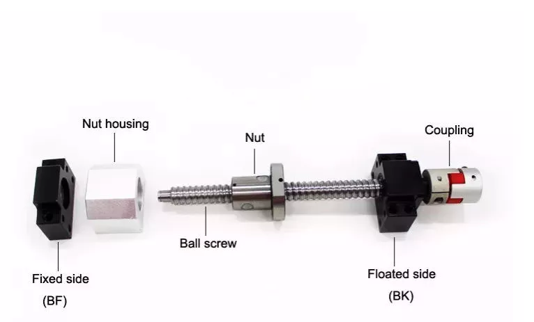
When selecting a ball screw for your application, there are several factors to consider. This article will discuss high mechanical efficiency, low friction, multiple repair options, and application requirements. Choosing the right ball screw can help you get the job done quickly and effectively. To make your decision easier, consider the following tips. Read on to learn about some of the advantages of ball screws and how they can benefit your applications. Here are some of the most common types:
air-compressor

High mechanical efficiency

The mechanical efficiency of ball screws can be measured using the axial load test. The axial load is equal to 0.5 x FPr / 2Fpr. The elastic deformations are measured as DL1 and DL2, respectively. Common engineering procedures work at 90 percent reliability; however, certain sectors require higher reliability, which has a direct impact on the dynamic load capacity. The axial load test is 1 of the most widely used methods to determine the mechanical efficiency of ball screws.
In order to achieve high translation, ball screws must be designed with high stiffness and positioning accuracy. In addition, high preloads increase the initial driving torque and cause more friction and heat. Other important design criteria include low driving torque and reduced slip motion. This means that the high translation capacity of ball screws must be well matched to the overall application. The following are some common design criteria for ball screws. You can select the best type of ball screw for your needs.
The high mechanical efficiency of ball screw is achieved by avoiding the common sag and pitch problem. The ball track design helps to reduce the centrifugal force. The ball screw’s diameter can be adjusted by adjusting the centre pitch of the nut on 2 ball tracks. The nut’s axial load is also adjusted through the offset centre pitch. This method allows the users to increase the mechanical efficiency of ball screw by up to 40%.
When calculating the mechanical efficiency of ball screw, consider the application’s environment, speed, and other factors. If the application requires precision and accuracy, then the ball screw is the right choice. The engineering department of a ball screw manufacturer will carefully review the application factors and come up with a design that meets the application’s expectations. Moreover, some manufacturers even offer customized ball screws, which can be tailored to your requirements.

Low friction

The operating performance of a low-friction ball screw is characterized by its minimal friction. This screw has a structure that transmits forces through rolling steel balls. The torque is calculated by calculating the load and the lead screw’s dimensions. This type of screw can be used for a variety of different applications, including hydraulic systems. Read on to learn more about this type of screw and how it can help you build a more reliable and durable car.
The critical speed of a ball screw is higher than that of a lead screw, so this type of screw can accommodate larger loads and speeds. It also has a lower friction coefficient, which reduces the amount of heat produced. High-quality ball screws can withstand longer duty cycles than standard lead screws. However, in order to compare the two, you must take into account the duty cycle. Low-friction ball screws are more durable than lead screws, and the duty cycle is only 1 of the factors you should consider when selecting them.
The ball bearings are the most prominent component of a low-friction ball screw. Their main function is to reduce the friction between the nut and the shaft. Without them, the friction would be too high. This feature is possible thanks to the ball bearing’s groove profile. Two arcs intersect at the contact points on the shaft and nut. Consequently, the ball bearing reduces friction in a way that is essentially non-existent without the bearing.
The mechanical efficiency of a low-friction ball screw is very high. The typical ball screw is up to 90% efficient, but some types can reach a higher efficiency. They are commonly used in machine slides, presses, and linear actuators. The high efficiency of a low-friction ball screw makes it a great choice for many different applications. This type of screw is made of several main components. The ball bearings provide the helical raceway for the ball assembly and threaded shaft is the screw part. The ball screw is comparatively more bulky than a conventional leadscrew, but the overall size is smaller than its lead counterpart.
air-compressor

Multiple repair options

A damaged ball screw will typically display visible physical signs, including noise or vibration. Additionally, worn ball screws will require more horsepower and torque to operate. They may also cause lead accuracy issues. Luckily, there are multiple repair options for ball screws. You can get new ball screws to restore preload and reduce backlash. But there are some warning signs to look out for first. Keeping a close eye on your ball screw’s health can help you avoid a costly replacement.
Look for a ball screw repair company with a proven track record of servicing all types of ball screws. The service should offer a free evaluation and 3 types of service: reload, recondition, and replacement. Reload is the simplest option and involves cleaning and polishing the screw and ball nut. Reconditioning or replacement, on the other hand, requires new parts. Choose the 1 that offers the best value for your money.
EP offers an emergency service and superior service for your ball screws. Their UK service includes delivery and international shipping. All ballscrew repairs are covered by a full service warranty, and the company is known for providing competitive pricing. If you do need a ball screw repair, look no further. Contact K+S today to discuss your specific needs. You’ll be glad you did. You’ll save up to 70% over purchasing a new ball screw.
While ball screw repair is an easy and inexpensive option, it may be necessary to have it replaced more frequently than the usual. In addition to replacing worn ball screws, you may need to consider a different type of repair. This process involves grinding the ball nut and journal diameters back to their original size. Fortunately, level 4 is the most expensive but can restore a screw’s lifespan. This is also the most extensive type of repair available for a ball screw.

Application requirements

A ball screw is an efficient solution for precision motion control in many applications, including automotive and aerospace. These screw-type devices are highly resistant to corrosion, and the alternating steel-ceramic architecture ensures extreme reliability and sturdiness. For the aerospace sector, a ball screw replaces the typical hydraulic system, and the product is used in wind turbine blade pitch and directional position, solar panel movement, and gate control in hydroelectric stations. Ball screws are also used in motorised inspection tables, step photolithography machines, microscopic integrated circuits, and many other applications.
The most critical requirements for a ball screw assembly are backlash and bearing support. Backlash is the amount of axial motion between the screw and nut, which leads to positioning errors. Although this axial motion is minimal, it can be as little as 70um. If the preload is too large, a ball screw may suffer from excessive heat. Depending on the application, the amount of preload required can be adjusted to maximize the overall performance of the device.
The choice of screw is determined by the load capacity. For example, plastic nuts are commonly used for light loads, while bronze nuts are used for loads that weigh several thousand pounds. Lead screws are not particularly reliable in situations where load requirements are extremely high, and a ball screw will often be a better option. The lower friction of a ball screw allows it to withstand higher duty cycles than a lead screw. When the load requirements exceed lead screws’ capacity, a ball screw is the better choice.
A step photolithography machine is another example of an application where ball screws play an important role. This device helps manufacturers produce microscopic integrated circuits by harnessing the reaction of light. A stepper is a critical piece of this machine, as it controls the positioning of light exposure on the silicon wafer. High precision is required for this application. Ultimately, a ball screw will make the process easier. Its proven record for meeting instrumentation requirements is an excellent example of its value in the laboratory.
air-compressor

Cost

The global market for ball screws is growing at a steady pace, but what drives the growth? In the ball screw industry, performance, cost, and analytical predictability are the primary concerns of OEMs. This market study provides in-depth analysis of these market dynamics. You’ll learn how to best compete in the global market for ball screws. Here are some tips to help you get started:
Ensure you have a good grasp of the differences between lead and ball screws. The cost of lead screws depends on their efficiency, and some of them can achieve C5 level accuracy. However, ball screws are more durable and more repeatable. Besides, lead screws can’t achieve high precision because of their sliding motion, which gradually grinds away the accuracy. As a result, the cost of a ball screw is more than compensated by the improved performance of OEMs.
To get the best price for ball screw, look for a manufacturer with a strong technical force. Most of these manufacturers have sophisticated equipment and strict quality control systems. They draw inspiration from the requirements of the market and have continuously increased their technological content to stay ahead of the competition. If you’re in Pune, look for a manufacturer with this technology. It won’t be difficult to do business with such a supplier. The company will also provide you with contact information, including their office address and phone numbers.
When choosing between lead and ball screws, you need to understand how they work and why they’re more reliable. Ball screws are more durable than lead screws, which is 1 of the primary reasons for their popularity. Lead screws, on the other hand, are often used for vertical applications. Lead screws tend to be cheaper than ball screws, but they have more limitations. When used properly, however, they can increase the life and performance of machines. In general, they’re corrosion-resistant and offer great design flexibility.

China high quality Factory Direct Multiple Model Spare Parts     near me manufacturer China high quality Factory Direct Multiple Model Spare Parts     near me manufacturer

China Hot selling CZPT Used CZPT 6X4 10 Wheels Primary Tractor Truck Truck Parts near me supplier

Product Description

Sinotruk Used CZPT 6X4 10 Wheels Primary Tractor Truck Truck Parts
Product Description
Our main products include dump truck, tractor, oil tank truck, on-board crane, low bed semi-trailer, flat semi-trailer, bulk cement semi-trailer, skeleton semi-trailer and its accessories. As we are factory direct sales, the quality is guaranteed

Detailed Photos


Product parameters

VEHICLE SPECIFICATION DESCRIPTION
Truck Model ZZ4257S3241W
Type of Vehicle TRACTOR TRUCK 
Truck Brand SINOTRUK-HOWO 
Driving Position Left hand Driving and right hand Driving
Fuel tanker capacity(L) 400
The Total Mass 40,000kg
Dead Weight 8800
Max speed(km/h)(km/h) 102                  
Color  Optional 
Chassis & Add Components 
Frame Details High-Strength U-profile ladder frame with section of 300*90*8mm and reinforced sudfram, all cold riveted cross members.
Dimension(Lx W xH)(unloaded)(mm) 6800x2500x3400
Approaching angle/Departure angle(°)  16/70
Overhang(front/rear) (mm) 1500/725
Wheel base (mm) 3225+1350
Engine 
Model WD615.47
Power 371hp/272kw.2000r/min
Emission  EURO II 
Cylinder bore*stroke(mm) 126*155
Displacement(L) 9.876
Type water-cooled,four strokes,6 cylinders in line,turbocharged, directly injection
Kind of Fuel Diesel 
Fuel Consumption(L/100km) 28L/100km
Clutch & Gear Box System
Clutch SINOTRUKΦ430mm diaphragm spring clutch
Gear Box HW19710 , 10 forward & 2 reverse gearbox
Axles
Front Axle Model HF9 axle. Capacity: 9000kg
Rear Axle HC16T axle. Capacity:2* 16000kg
Ratio of rear axle 3.91 /4.875/5.833
Electrical System
Battery  2pcs *12V/165Ah
Alternator 28V-1500kw
Starter  7.5Kw/24V
Brake System 
Service brake Dual circuit compressed air brake 
Parking brake spring energy, compressed air operating on rear wheels 
Auxiliary brake  Engine exhaust brake 
Steering system 
Model ZF8118
Type  hydraulic steering with power assistance
Wheels & Tyres 
Type 12R22.5 or 315/80R22.5
Material  Tubeless tires
Quantity 10+1 spare 
Kin pin 90mm
Cabin
Type HW76 Standard cabin 
HW76 roof long cabin, 1 sleepers, with air conditioner, German VDO instrument and electronic controlled system, four-point support fully floating spring suspension +shock absorbers with transverse stabilizer, both the drive seat and the co-driver seat have the double locking organization safety belts, exterior sun visor, inner side sun shield, the alarming system of the alternator when there is something wrong.

Shipping

About Us

FAQ

1.What is your terms of shipment?
Generally,we ship our truck by ro-ro ship,bulk cargo vessel,container etc.
2. How to ensure quality?
Our raw materials and OEM accessories (including axles, suspension and tires) are purchased centrally within the group, and each node will be subject to strict inspection. Professional workers and advanced equipment are used in the whole process to ensure the high quality of each part.

3. What are your terms of payment?
Our payment method is flexible. The first choice is telegraphic transfer or letter of credit. Of course, all payment methods can be negotiated.

4.Is there any MOQ requirement?
No MOQ requirement, and we are even CZPT to provide the Express service if parts are urgently needed.

Calculate the ideal mechanical advantage of pulleys

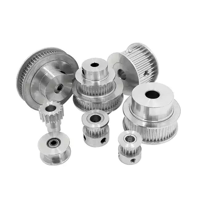
The basic equations for pulleys can be found in this article. It will also cover the different types of pulleys, the ideal mechanical advantages of pulleys, and some common uses of pulley systems. Read on to learn more! After all, a pulley is a simple mechanical device that changes the direction of a force. Learn more about pulleys and their common uses in engineering.
pulley

pulley basic equation

Pulleys work the same way as gravity, so they should withstand similar forces. Newton’s laws of motion can be used to calculate the forces in a pulley system. The second law of motion applies to forces and accelerations. Similar to this is Newton’s third law, which states that the directions of forces are equal and opposite. The fourth law dictates the direction of force. The Fifth Law states that tension is in equilibrium with gravity.
A pulley is a simple mechanism that transmits force by changing direction. They are generally considered to have negligible mass and friction, but this is only an approximation. Pulleys have different uses, from sailboats to farms and large construction cranes. In fact, they are the most versatile mechanisms in any system. Some of their most common applications and equations are listed below.
For example, consider 2 masses m. Those of mass m will be connected by pulleys. The static friction coefficient of the left stop is ms1, and the static friction coefficient of the right stop is ms2. A no-slip equation will contain multiple inequalities. If the 2 blocks are considered to be connected by a pulley, the coefficient of kinetic friction is mk. In other words, the weight of each block carries the same mass, but in the opposite direction.

Types of pulleys

A pulley is a device used to pull and push objects. Pulley systems are ropes, cables, belts or chains. The “drive pulley” is attached to the shaft and moves the driven pulley. They are available in a variety of sizes, and the larger they are, the higher the speed of power transmission. Alternatively, use small pulleys for smaller applications.
Two-wheel pulleys have 2 mechanical advantages. The greater the mechanical advantage, the less force is required to move the object. More wheels lift more weight, but smaller pulleys require less force. In a two-wheel pulley system, the rope is wound around 2 axles and a fixed surface. As you pull on the rope, the shafts above slowly come together.
Compound pulleys have 2 or more rope segments that are pulled up on the load. The mechanical advantage of compound pulleys depends on the number of rope segments and how they are arranged. This type of pulley can increase the force by changing the direction of the rope segment. There are 2 main types of pulleys. Composite pulleys are most commonly used in construction. The ideal mechanical advantage of pulleys is 2 or more.
Construction pulleys are a basic type. They are usually attached to wheel rails and can be lifted to great heights. Combinations of axes are also common. Construction pulleys can be raised to great heights to access materials or equipment. When used in construction, these pulleys are usually made of heavy materials such as wood or metal. They are secured with ropes or chains.

The ideal mechanical advantage of pulleys

The pulley system is a highly complex system with high mechanical advantages. Use a single pulley system to reduce the force required to lift an object by cutting it in half. The mechanical advantage increases as you add more pulleys, such as 6 or seven. To calculate the mechanical advantage of a pulley system, you need to count the number of rope segments between the pulleys. If the free end of the rope is facing down, don’t count it. If it’s facing up, count. Once you have your number, add it up.
The required mechanical advantage of a pulley is the number of rope segments it has to pull the load. The more rope segments, the lower the force. Therefore, the more rope segments the pulley has, the lower the force. If the rope segments are four, then the ideal mechanical advantage is four. In this case, the composite pulley quadrupled the load force.
The ideal mechanical advantage of a pulley system is the sum of the mechanical force and the force required to lift the load at its output. Typically, a single pulley system uses 2 ropes, and the mechanical force required to lift the load is multiplied by the 2 ropes. For a multi-pulley system, the number of ropes will vary, but the total energy requirement will remain the same. The friction between the rope and pulley increases the force and energy required to lift the load, so the mechanical advantage diminishes over time.
pulley

Common uses of pulley systems

A pulley system is a simple mechanical device typically used to lift heavy objects. It consists of a rotating wheel attached to a fixed shaft and a rope attached to it. When the wheel moves, the force applied by the operator is multiplied by the speed of the pulley, and the force is multiplied by the weight of the object being lifted. Common uses for pulley systems include pulling, lifting, and moving heavy objects.
The oil and petroleum industries use pulley systems in a variety of applications. Most commonly, pulleys are used in drilling operations and they are installed on top of the rig to guide the cable. The cable itself is attached to 2 pulleys suspended in the derrick, where they provide mechanical energy to the cable. Using a pulley system in this application provides the force needed to move the cable safely and smoothly.
The main advantage of the pulley system is that it minimizes the force required to lift an object. The force used to lift the object is multiplied by the desired mechanical advantage. The more rope segments, the lower the force required. On the other hand, a compound pulley system can have many segments. Therefore, a compound pulley system can increase the force a worker can exert on an object.
Safety Precautions to Take When Working on Pulley Systems

There are many safety precautions that should be observed when working on a pulley system. The first is to wear proper protective gear. This includes hard hats that protect you from falling objects. Also, gloves may be required. You should limit the amount of movement in the penalty area, and you should also keep the area free of unnecessary people and objects. Also, remember to wear a hard hat when working on the pulley system.
Another important safety precaution when working on a pulley system is to check the Safe Working Load (SWL) of the pulley before attaching anything. This will help you understand the maximum weight the pulley can hold. Also, consider the angle and height of the pulley system. Always use safety anchors and always remember to wear a hat when working on a pulley system.
Safe use of chain hoists requires training and experience. It is important to read the manufacturer’s manual and follow all safety precautions. If you’re not sure, you can actually inspect the hoist and look for signs of damage or tampering. Look for certifications for sprocket sets and other lifting accessories. Look for the Safe Working Load (SWL) marking on the chain hoist.
pulley

Example of a pulley system

Pulley systems are often used to lift items. It allows you to reduce the effort to lift and move the load by applying force in 1 direction. Pulley systems can be built and modeled to fit any type of project. This resource focuses on pulley systems and is designed to support the new GCSEs in Engineering, Design and Technology. There are also many examples of pulley systems suitable for various applications.
In the study, participants who read easy text took longer to manipulate the pulley system than those who read challenging text. In general, this suggests that participants with prior scientific experience used their cognitive abilities more effectively. Additionally, students who read simple texts spent less time planning the pulley system and more time on other tasks. However, the study did show that the time required to plan the pulley system was similar between the 2 groups.
In everyday life, pulley systems are used to lift various objects. Flagpoles are 1 of many pulley systems used to raise and lower flagpoles. They can also be used to raise and lower garage doors. Likewise, rock climbers use pulleys to help them ascend and descend. The pulley system can also be used to extend the ladder.

China Hot selling CZPT Used CZPT 6X4 10 Wheels Primary Tractor Truck Truck Parts     near me supplier China Hot selling CZPT Used CZPT 6X4 10 Wheels Primary Tractor Truck Truck Parts     near me supplier

China Good quality Aluminum 5 Axis CNC Machining Stainless Steel Parts with Best Sales

Product Description

 aluminum 5 axis cnc machining stainless steel parts


Product Description

      
         The auto hardware accessories we produce have reached cooperation with famous Japanese auto suppliers for many years. In terms of delivery, we will deliver on time and without delay. Special-shaped accessories are unique, and we have a complete supply chain. The system, from mold manufacturing, to raw material purchase, to production, has a complete process, which enables our production to proceed smoothly and quickly. In addition, production workers can implement a shift system for uninterrupted production to ensure delivery.


Product Name : Sheet metal fabrication 
Our Service: OEM/ODM sheet metal fabrication
Material: Aluminium Profile/Aluminum Plate/Stainless Steel /SGCC 
Bending: 0 ~ +/-0.1mm 
CNC machining: 0 ~ +/-0.1mm 
Delivery time: 3-7 days for sample. Mass production depends on the quantity.

Production Technology


Our Advantages


Detailed Photos


Packaging & Shipping


     In terms of product packaging, we adopt a more careful packaging method to protect metal accessories more safely. Due to the humid air at sea and high salt content, it is more corrosive to metal products. Buyers often store these products in the warehouse after they buy them back, so we make the hardware accessories less likely to be exposed to sea air during the shipping process through careful packaging, thereby avoiding the problem of rust. We tend to put moisture-proof agents in cartons, wooden boxes, and iron boxes. After packaging, it is sealed with plastic film to keep out the air.


Certifications


Company Profile

         HangZhou Lianrun Hardware Products Co., Ltd. is a custom metalworking manufacturer specializing in metal stamping, deep drawing stamping and machining. Has an independent export qualification and an experienced foreign trade team. Since 2003, the company has been providing all customers with customized services for auto parts and accessories, hardware tool parts, metal crafts. Our team will help you reduce tooling investment and reduce part cost according to your requirements. Please send us your design drawings and samples for our prompt and high quality quotation. Bring you high-efficiency production capacity through modern workshops and workers.


FAQ

1.Q:Company products can be customized according to the corresponding specifications provided by us?
        Yes,We can provide customized service.

2.Q:Product material can guarantee?
        Completely, with special certification.

3.Q:Product delivery, delivery time will be long?
       
We will control the delivery with high quality and efficiency within the time limit you require.

4.Q:Are you a factory or a trading company?
       
We are a custom factory.

5.Q:How long is your delivery time?
       
Our delivery time is usually 10 to 25 days, or depending on the quantity.

6.Q:What are the payment terms?
       
30% T / T in advance, balanced before shipment.We provide photos, videos and even third parties to check.

7.Q:How do you ensure quality control?
       
100% quality inspection before packaging, the pass rate is over 99.5%.

How to Assemble a Pulley System

A pulley is a wheel that rotates on a shaft or shaft to support the movement of a taut cable. Pulleys allow power to be transmitted from the shaft to the cable.
pulley

Simple pulley

The simplest theory of operation of a pulley system assumes that the rope and weight are weightless and that the rope and pulley are not stretched. Since the force on the pulley is the same, the force on the pulley shaft must also be zero. Therefore, the force exerted on the pulley shaft is also distributed evenly between the 2 wires passing through the pulley. The force distribution is shown in Figure 1.
The use of simple pulleys is as old as history. Before the Industrial Revolution, people relied on muscle strength to carry heavy loads. Pulleys, levers and ramps make this possible. Today, we can see pulleys in a variety of systems, from exercise equipment to garage doors, and even rock climbers use them to help them reach greater heights. As you can see, these simple machines have been around for centuries and are used in everyday life.
Another simple pulley system is the pulley system. In this system, there is a fixed pulley at the top and a movable pulley at the bottom. The 2 pulleys are connected by a rope. This combination reduces the amount of work required to lift the load. Additionally, the ropes used in this system are usually made of rope and woven through the individual wheels of the pulley drum.
A pulley is an ingenious device that distributes weight evenly and can be used to lift heavy objects. It is easy to build and can be easily modified for a wide range of activities. Even young children can make their own with very few materials. You can also use simple household items such as washing machines, thin textbooks and even chopsticks. It’s very useful and can be a great addition to your child’s science and engineering activities.
The simplest pulley system is movable. The axis of the movable pulley can move freely in space. The load is attached to 1 end of the pulley and the other end to the stationary object. By applying force on the other end of the rope, the load is lifted. The force at the other end of the rope is equal to the force at the free end of the pulley.
Another form of pulley is the compound pulley. Compound pulleys use 2 or more wheels to transmit force. Compound pulleys have 2 or more wheels and can lift heavier objects. Dim is POLE2.
pulley

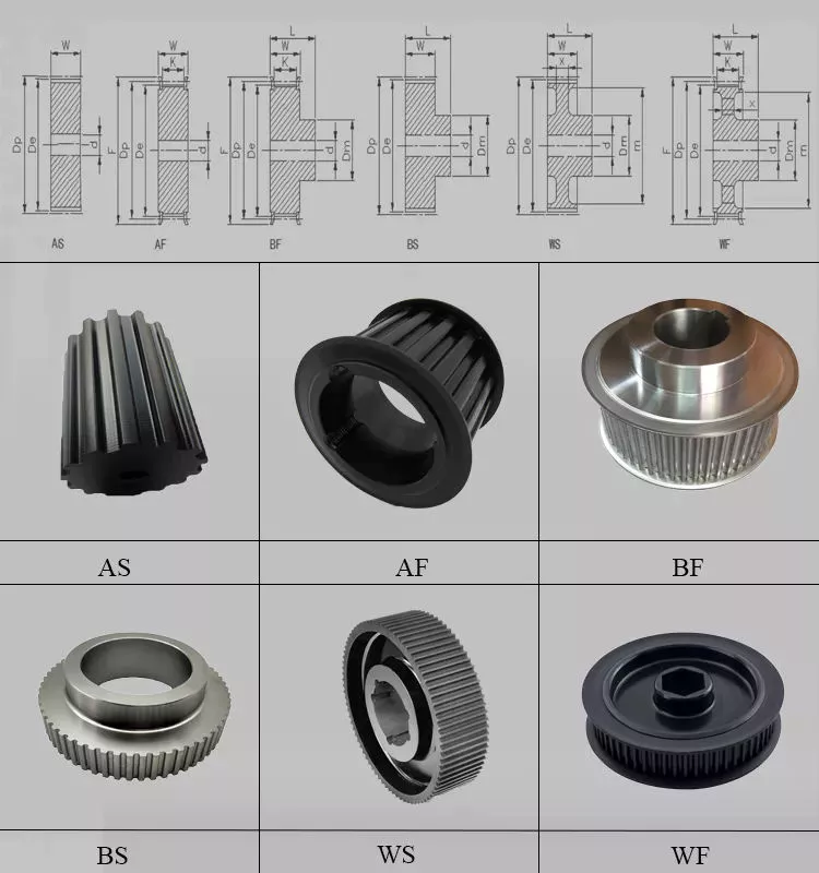
tapered pulley

It is important to clean and align the bolt holes before assembling the tapered pulley. The screws should be lubricated and the threads cleaned before installation. To install the pulley, insert it into the shaft keyway. The keyway should be aligned with the shaft hole to prevent foreign matter from entering the pulley. Then, alternately tighten the bolts until the pulley is tightened to the desired torque.
A tapered pulley is a basic structure. The pulley belt is arranged across 4 steps. Installed between the headstock casting and the main shaft, it is often used in the paper industry. It integrates with printing machinery and supports assembly lines. These pulleys are also available in metric range options, eliminating the need for ke-waying or re-drilling. They are easy to install, and users can even customize them to suit their needs.
CZPT Private Limited is a company that provides unique products for various industries. This large product is used for many different purposes. Also, it is manufactured for industrial use. The company’s website provides detailed specifications for the product. If you need a tapered pulley, contact a company in your area today to purchase a quality product!
Tapered pulleys are vital to paper mill machinery. Its special design and construction enable it to transmit power from the engine source to the drive components. The advantages of this pulley include low maintenance costs and high mechanical strength. Cone wheel diameters range from 10 inches to 74 inches. These pulleys are commonly used in paper mills as they offer low maintenance, high mechanical strength and low wear.
A tapered sleeve connects the pulley to the shaft and forms an interference fit connector. The taper sleeve is fixed on the shaft with a key, and the corresponding inner hole is fixed on the shaft with a key. These features transmit torque and force to the pulley through friction. This allows the tapered pulley to move in a circular motion. The torque transfer characteristics of this pulley are most effective in high speed applications.
The sleeve is the most important part when assembling the tapered pulley. There is an 8-degree taper inside the cone, which is closely connected to the inner surface of the pulley. Taper sleeves and pulleys are interchangeable. However, tapered pulleys can be damaged after prolonged use.
pulley

pulley pulley system

A pulley pulley system is a great way to move heavy objects. These systems have been around for centuries, dating back to the ancient Greeks. This simple mechanism enables a person to lift heavy objects. These blocks are usually made of rope, and the number of turns varies for different types of rope. Some blocks have more cords than others, which creates friction and interferes with the easy movement of the lifting system.
When using a pulley pulley, the first thing to decide is which direction to pull. Unfavorable rigging means pulling in the opposite direction. In theory, this method is less efficient, but sometimes requires a certain amount of work space. The benefit is that you will increase the mechanical advantage of the pulley by pulling in the opposite direction. So the interception and tackle system will give you more of a mechanical advantage.
Pulley pulleys are an excellent choice for lifting heavy objects. The system is simple to install and users can easily lift objects without extensive training. Figure 3.40 shows a pulley in action. In this photo, the person on the left is pulling a rope and tying the end of the rope to a weight. When the rope is attached to the load, the rope will be pulled over the pulley and pulley.
The blocks on the blocks are attached to the ends of the rope. This creates unique lifting advantages compared to single-line systems. In Figure 3, the tension of each thread is equal to one-third of the unit weight. When the rope is pulled over the pulley, the force is divided equally between the 2 wires. The other pulley reverses the direction of the force, but that doesn’t add any advantage.
Use pulleys to reduce traction and load. The weight of the load has not changed, but the length of the rope has increased. Using this method, lifting the load by pulling the rope 4 times reduces the force required to lift 1 foot. Likewise, if the pulley system had 4 pulleys instead of three, the length of the rope would be tripled.
The system can transmit loads in any direction. Rope length is determined by multiplying the distance from the fixed block to the load by the mechanical advantage. If the mechanical advantage is 3:1, then passing the rope through the pulley 3 times will produce the required traction distance. Also, the length of the rope will depend on the mechanical advantage, so if the load is 3 times the length of the rope, it will be more than 3 times the required length.

China Good quality Aluminum 5 Axis CNC Machining Stainless Steel Parts     with Best SalesChina Good quality Aluminum 5 Axis CNC Machining Stainless Steel Parts     with Best Sales

China Professional Air Powered Flux Recovery Parts for Arc Welding Tractor with Free Design Custom

Product Description

Model Details
TC-SUPER-B2 0.6Mpa,Air powered
Professional flux recovry machine factory,contact us to get more details 

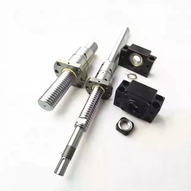
Standard Length Splined Shafts

Standard Length Splined Shafts are made from Mild Steel and are perfect for most repair jobs, custom machinery building, and many other applications. All stock splined shafts are 2-3/4 inches in length, and full splines are available in any length, with additional materials and working lengths available upon request and quotation. CZPT Manufacturing Company is proud to offer these standard length shafts.
splineshaft

Disc brake mounting interfaces that are splined

There are 2 common disc brake mounting interfaces, splined and center lock. Disc brakes with splined interfaces are more common. They are usually easier to install. The center lock system requires a tool to remove the locking ring on the disc hub. Six-bolt rotors are easier to install and require only 6 bolts. The center lock system is commonly used with performance road bikes.
Post mount disc brakes require a post mount adapter, while flat mount disc brakes do not. Post mount adapters are more common and are used for carbon mountain bikes, while flat mount interfaces are becoming the norm on road and gravel bikes. All disc brake adapters are adjustable for rotor size, though. Road bikes usually use 160mm rotors while mountain bikes use rotors that are 180mm or 200mm.
splineshaft

Disc brake mounting interfaces that are helical splined

A helical splined disc brake mounting interface is designed with a splined connection between the hub and brake disc. This splined connection allows for a relatively large amount of radial and rotational displacement between the disc and hub. A loosely splined interface can cause a rattling noise due to the movement of the disc in relation to the hub.
The splines on the brake disc and hub are connected via an air gap. The air gap helps reduce heat conduction from the brake disc to the hub. The present invention addresses problems of noise, heat, and retraction of brake discs at the release of the brake. It also addresses issues with skewing and dragging. If you’re unsure whether this type of mounting interface is right for you, consult your mechanic.
Disc brake mounting interfaces that are helix-splined may be used in conjunction with other components of a wheel. They are particularly useful in disc brake mounting interfaces for hub-to-hub assemblies. The spacer elements, which are preferably located circumferentially, provide substantially the same function no matter how the brake disc rotates. Preferably, 3 spacer elements are located around the brake disc. Each of these spacer elements has equal clearance between the splines of the brake disc and the hub.
Spacer elements 6 include a helical spring portion 6.1 and extensions in tangential directions that terminate in hooks 6.4. These hooks abut against the brake disc 1 in both directions. The helical spring portion 5.1 and 6.1 have stiffness enough to absorb radial impacts. The spacer elements are arranged around the circumference of the intermeshing zone.
A helical splined disc mount includes a stabilizing element formed as a helical spring. The helical spring extends to the disc’s splines and teeth. The ends of the extension extend in opposite directions, while brackets at each end engage with the disc’s splines and teeth. This stabilizing element is positioned axially over the disc’s width.
Helical splined disc brake mounting interfaces are popular in bicycles and road bicycles. They’re a reliable, durable way to mount your brakes. Splines are widely used in aerospace, and have a higher fatigue life and reliability. The interfaces between the splined disc brake and BB spindle are made from aluminum and acetate.
As the splined hub mounts the disc in a helical fashion, the spring wire and disc 2 will be positioned in close contact. As the spring wire contacts the disc, it creates friction forces that are evenly distributed throughout the disc. This allows for a wide range of axial motion. Disc brake mounting interfaces that are helical splined have higher strength and stiffness than their counterparts.
Disc brake mounting interfaces that are helically splined can have a wide range of splined surfaces. The splined surfaces are the most common type of disc brake mounting interfaces. They are typically made of stainless steel or aluminum and can be used for a variety of applications. However, a splined disc mount will not support a disc with an oversized brake caliper.

China Professional Air Powered Flux Recovery Parts for Arc Welding Tractor     with Free Design CustomChina Professional Air Powered Flux Recovery Parts for Arc Welding Tractor     with Free Design Custom

China OEM Custom Tractor Precision Investment Steel Casting Stainless Steel Aluminium Casting Car Parts with Hot selling

Product Description

Custom Tractor precision investment steel casting stainless steel aluminium casting car parts

Product name die cast car engine enclosure  parts
Material ADC12,A380,and others
Drawing file .pdf.stp.igs .
Mold led time  40-60days
Sample we offer free samples.
Certificates TUV
MOQ Low moq,1 pcs for sample checking is available 
CMM inspection Available
Service offer assembly if customer’s need

Introduction to die casting factory:
 

Aluminum die cast process is a process in which the molten liquid of aluminum alloy is poured into the mold and solidified into a casting under the action of pressure.
Our factory has 180-1260 tons of cold die casting machine, which adopts high-pressure casting. The product produced by us not only have high surface tolerance grade, good roughness and high strength, but also have high productivity,at least 50000 pcs per month,and our product scrap rate is controlled within 2%. At the same time, we are also equipped with a CMM to detect and control the product tolerance and size within the range of customer requirements,and it’s toelrance is 0.005.We also provide assembly service if customers requires.
 

Development example:


FAQ
Q1. Can I have a sample order for Die casting product?
A: Yes, we welcome sample order to test and check quality. Mixed samples are acceptable.

Q2. What about the lead time?
A:Sample needs 3-5 days, mass production time needs 1-2 weeks for order quantity more than.

Q3. Do you have any MOQ limit for Die casting product order?
A: Low MOQ, 1pc for sample checking is available.
 
Q4. How do you ship the goods and how long does it take to arrive?
A: We usually ship by DHL, UPS, FedEx or TNT. It usually takes 3-5 days to arrive. Airline and sea shipping also optional.

Q5. How to proceed an order for Die casting product?
A: Firstly let us know your requirements or application. Secondly We quote according to your requirements or our suggestions. Thirdly customer confirms the samples and places deposit for formal order. Fourthly We arrange the production.
 
Q6. Is it OK to print my logo on Die casting product?
A: Yes. Please inform us formally before our production and confirm the design firstly based on our sample.

Q7: Do you offer guarantee for the products?
A: Yes, we offer 2-5 years warranty to our products.
 
Q8: How to deal with the faulty?
A: Firstly, Our products are produced in strict quality control system and the defective rate will be less than 0.2%. Secondly, during the guarantee period, we will send new lights with new order for small quantity. For defective batch products, we will repair them and resend them to you or we can discuss the solution i ncluding re-call according to real situation.

Advantages of Ball Screws and How They Can Benefit Your Applications

When selecting a ball screw for your application, there are several factors to consider. This article will discuss high mechanical efficiency, low friction, multiple repair options, and application requirements. Choosing the right ball screw can help you get the job done quickly and effectively. To make your decision easier, consider the following tips. Read on to learn about some of the advantages of ball screws and how they can benefit your applications. Here are some of the most common types:
air-compressor

High mechanical efficiency

The mechanical efficiency of ball screws can be measured using the axial load test. The axial load is equal to 0.5 x FPr / 2Fpr. The elastic deformations are measured as DL1 and DL2, respectively. Common engineering procedures work at 90 percent reliability; however, certain sectors require higher reliability, which has a direct impact on the dynamic load capacity. The axial load test is 1 of the most widely used methods to determine the mechanical efficiency of ball screws.
In order to achieve high translation, ball screws must be designed with high stiffness and positioning accuracy. In addition, high preloads increase the initial driving torque and cause more friction and heat. Other important design criteria include low driving torque and reduced slip motion. This means that the high translation capacity of ball screws must be well matched to the overall application. The following are some common design criteria for ball screws. You can select the best type of ball screw for your needs.
The high mechanical efficiency of ball screw is achieved by avoiding the common sag and pitch problem. The ball track design helps to reduce the centrifugal force. The ball screw’s diameter can be adjusted by adjusting the centre pitch of the nut on 2 ball tracks. The nut’s axial load is also adjusted through the offset centre pitch. This method allows the users to increase the mechanical efficiency of ball screw by up to 40%.
When calculating the mechanical efficiency of ball screw, consider the application’s environment, speed, and other factors. If the application requires precision and accuracy, then the ball screw is the right choice. The engineering department of a ball screw manufacturer will carefully review the application factors and come up with a design that meets the application’s expectations. Moreover, some manufacturers even offer customized ball screws, which can be tailored to your requirements.

Low friction

The operating performance of a low-friction ball screw is characterized by its minimal friction. This screw has a structure that transmits forces through rolling steel balls. The torque is calculated by calculating the load and the lead screw’s dimensions. This type of screw can be used for a variety of different applications, including hydraulic systems. Read on to learn more about this type of screw and how it can help you build a more reliable and durable car.
The critical speed of a ball screw is higher than that of a lead screw, so this type of screw can accommodate larger loads and speeds. It also has a lower friction coefficient, which reduces the amount of heat produced. High-quality ball screws can withstand longer duty cycles than standard lead screws. However, in order to compare the two, you must take into account the duty cycle. Low-friction ball screws are more durable than lead screws, and the duty cycle is only 1 of the factors you should consider when selecting them.
The ball bearings are the most prominent component of a low-friction ball screw. Their main function is to reduce the friction between the nut and the shaft. Without them, the friction would be too high. This feature is possible thanks to the ball bearing’s groove profile. Two arcs intersect at the contact points on the shaft and nut. Consequently, the ball bearing reduces friction in a way that is essentially non-existent without the bearing.
The mechanical efficiency of a low-friction ball screw is very high. The typical ball screw is up to 90% efficient, but some types can reach a higher efficiency. They are commonly used in machine slides, presses, and linear actuators. The high efficiency of a low-friction ball screw makes it a great choice for many different applications. This type of screw is made of several main components. The ball bearings provide the helical raceway for the ball assembly and threaded shaft is the screw part. The ball screw is comparatively more bulky than a conventional leadscrew, but the overall size is smaller than its lead counterpart.
air-compressor

Multiple repair options

A damaged ball screw will typically display visible physical signs, including noise or vibration. Additionally, worn ball screws will require more horsepower and torque to operate. They may also cause lead accuracy issues. Luckily, there are multiple repair options for ball screws. You can get new ball screws to restore preload and reduce backlash. But there are some warning signs to look out for first. Keeping a close eye on your ball screw’s health can help you avoid a costly replacement.
Look for a ball screw repair company with a proven track record of servicing all types of ball screws. The service should offer a free evaluation and 3 types of service: reload, recondition, and replacement. Reload is the simplest option and involves cleaning and polishing the screw and ball nut. Reconditioning or replacement, on the other hand, requires new parts. Choose the 1 that offers the best value for your money.
EP offers an emergency service and superior service for your ball screws. Their UK service includes delivery and international shipping. All ballscrew repairs are covered by a full service warranty, and the company is known for providing competitive pricing. If you do need a ball screw repair, look no further. Contact K+S today to discuss your specific needs. You’ll be glad you did. You’ll save up to 70% over purchasing a new ball screw.
While ball screw repair is an easy and inexpensive option, it may be necessary to have it replaced more frequently than the usual. In addition to replacing worn ball screws, you may need to consider a different type of repair. This process involves grinding the ball nut and journal diameters back to their original size. Fortunately, level 4 is the most expensive but can restore a screw’s lifespan. This is also the most extensive type of repair available for a ball screw.

Application requirements

A ball screw is an efficient solution for precision motion control in many applications, including automotive and aerospace. These screw-type devices are highly resistant to corrosion, and the alternating steel-ceramic architecture ensures extreme reliability and sturdiness. For the aerospace sector, a ball screw replaces the typical hydraulic system, and the product is used in wind turbine blade pitch and directional position, solar panel movement, and gate control in hydroelectric stations. Ball screws are also used in motorised inspection tables, step photolithography machines, microscopic integrated circuits, and many other applications.
The most critical requirements for a ball screw assembly are backlash and bearing support. Backlash is the amount of axial motion between the screw and nut, which leads to positioning errors. Although this axial motion is minimal, it can be as little as 70um. If the preload is too large, a ball screw may suffer from excessive heat. Depending on the application, the amount of preload required can be adjusted to maximize the overall performance of the device.
The choice of screw is determined by the load capacity. For example, plastic nuts are commonly used for light loads, while bronze nuts are used for loads that weigh several thousand pounds. Lead screws are not particularly reliable in situations where load requirements are extremely high, and a ball screw will often be a better option. The lower friction of a ball screw allows it to withstand higher duty cycles than a lead screw. When the load requirements exceed lead screws’ capacity, a ball screw is the better choice.
A step photolithography machine is another example of an application where ball screws play an important role. This device helps manufacturers produce microscopic integrated circuits by harnessing the reaction of light. A stepper is a critical piece of this machine, as it controls the positioning of light exposure on the silicon wafer. High precision is required for this application. Ultimately, a ball screw will make the process easier. Its proven record for meeting instrumentation requirements is an excellent example of its value in the laboratory.
air-compressor

Cost

The global market for ball screws is growing at a steady pace, but what drives the growth? In the ball screw industry, performance, cost, and analytical predictability are the primary concerns of OEMs. This market study provides in-depth analysis of these market dynamics. You’ll learn how to best compete in the global market for ball screws. Here are some tips to help you get started:
Ensure you have a good grasp of the differences between lead and ball screws. The cost of lead screws depends on their efficiency, and some of them can achieve C5 level accuracy. However, ball screws are more durable and more repeatable. Besides, lead screws can’t achieve high precision because of their sliding motion, which gradually grinds away the accuracy. As a result, the cost of a ball screw is more than compensated by the improved performance of OEMs.
To get the best price for ball screw, look for a manufacturer with a strong technical force. Most of these manufacturers have sophisticated equipment and strict quality control systems. They draw inspiration from the requirements of the market and have continuously increased their technological content to stay ahead of the competition. If you’re in Pune, look for a manufacturer with this technology. It won’t be difficult to do business with such a supplier. The company will also provide you with contact information, including their office address and phone numbers.
When choosing between lead and ball screws, you need to understand how they work and why they’re more reliable. Ball screws are more durable than lead screws, which is 1 of the primary reasons for their popularity. Lead screws, on the other hand, are often used for vertical applications. Lead screws tend to be cheaper than ball screws, but they have more limitations. When used properly, however, they can increase the life and performance of machines. In general, they’re corrosion-resistant and offer great design flexibility.

China OEM Custom Tractor Precision Investment Steel Casting Stainless Steel Aluminium Casting Car Parts     with Hot sellingChina OEM Custom Tractor Precision Investment Steel Casting Stainless Steel Aluminium Casting Car Parts     with Hot selling

China manufacturer SPCC Stainless Steel Stamping Precision Auto Sheet Metal Parts with Good Service near me shop

Product Description

Product Description

Process service

Laser & Punch cutting,CNC bending & Press,Welding & polished,assembly & packing

Certification:

ISO9001, SGS

Material

Aluminum, stainless steel, copper,bronze,iron

Surface Treatment

Anodizing,Polishing,Zinc Plating, Nickel Plating, Chrome Plating, Powder Coating, E-coating,Alodine ,blacken ect

Accuracy

Laser Cutting:+/-0.1mm ; CNC Bending:+/-0.1mm
Surface Roughness:Ra 3.2 Welding:+/-0.2mm

Application

Equipment/Telecommunication/Vehicle/Furniture,ect

Surface

Free of scratches,good fitness

Inspection

FAIR-First Article Inspection DURPO-During Production Inspection PSI-Pre-shipment Inspection

Weight Range

0.3-100KG

Edges&holes

Smooth

Drawing:

JPEG, PDF, CAD, IGS Accepted

Package

Inner pearl button,outside carton box,or customized

Payment:

30%T/T+70%T/T

OEM

OEM and ODM are welcome

Detailed Photos


The products shown here is only to present the scope of our business activities.

We can custom according to your drawings or samples.


Certifications


Company Profile

HangZhou Auchung Industrial Co., Ltd was founded in HangZhou since 2003, is dedicated to the R& D, manufacturing and sales of sheet metal products and CNC machining parts.
The precision metal parts and CNC machining parts we produced can meet the requirement in different filed, such as power equipment, medical equipment, communication industry, rail transit equipment industry, new energy series equipment, agricultural machinery, etc. We have 250 staffs including an experienced research and process design team which is more than 30 people. We strive to offer the best quality and service to support your business.
With rich experience of manufacturing, we aim to develop long term relationships with each and every 1 of our customers by delivering quality workmanship, on time and at a competitive cost. Through making customer satisfaction our top priority, we have been CZPT to go from strength to strength.
Our friendly, efficient and professional service and the ability to meet tight delivery deadlines have helped us to build a large customer base, and enabled us to attract business from a wide area.
We offer a wide range of services including
Numerical control machining
Electrical discharge wire cutting service,
Laser cutting
NC stamping
CNC machining
Bending forming process
Laser automatic welding
Surface painting process
Surface blasting
Assembly & Manual Machining
No matter what your project involves, with our fresh, flexible approach and forward thinking we are CZPT to assist customers with requirements that go beyond our standard range of products. Whatever our customers require, we can usually find a way to help achieve their goals.


Our Advantages

Technical Support

Auchung is professional at independent development and design. Our engineers are skilled at AUTO CAD, PRO ENGINEER, SOLID WORKS and other 2D & 3D softwares. We are CZPT to design, develop,produce and deliver your products according to your drawings, samples or just an idea. Dural control of standard products and OEM products.
 

We can supply products with follow test reports :

1)Chemical composition report

2)Tensile strength report

3)Brinell hardness report,Rockwell hardness.

4)Metallographic structure report

5)Key dimensions checking record report

6)Full dimension report

7)Third-party test report

Quality Control

1) Checking the raw material after they reach our factory——- Incoming quality control ( IQC)
2) Checking the details before the production line operated
3) Have full inspection and routing inspection during mass production—In process quality control(IPQC)
4) Checking the goods after they are finished—- Final quality control(FQC)
5) Checking the goods after they are finished—–Outgoing quality control(OQC)

Why Choose Us

1) Design assistance and full engineering support .
2) Professional at OEM CNC parts .
3) Complete production lines for custom laser cuting, bending, welding,turning, milling, CNC machining sheet metal fabrication, stamping, bending, argon welding
and surface treatment.
4) Advanced machine tools, CAD/CAM programming software.
5) Prototype machining capabilities.
6) Strict quality control standards with a highly qualified inspection department .
7) Continually upgrading and advancing our equipment to remain competitive .
8) Small quality is also available.

FAQ

Q: What do I need for offering a quote ?
A: Please offer us 2D or 3D drawings (with material, dimension, tolerance, surface treatment and other technical requirement etc.),quantity, application or samples.
Q: What is your MOQ?
A: MOQ depends on our client’s needs, besides,we welcome trial order before mass-production.
Q: What is the production cycle?
A: It varies a lot depending on product dimension,technical requirements and quantity. We always try to meet customers’
requirement by adjusting our workshop schedule.
Q: What kind of payment terms do you accept?
A.: T/T, L/C, Escrow, paypal, western union, moneygram etc.
Q: Is it possible to know how is myproduct going on without visiting your company?
A: We will offer a detailed products schedule and send weekly reports with digital pictures and videos which show the machining progress

Packaging & Shipping


Screw Shaft Types

If you’re looking for a screw shaft, but aren’t sure which type to buy, you’re in luck. In this article, we’ll talk about the different types, including Threaded shank, Round head, and Machined. Once you’ve read it, you’ll know which type to buy. Then, you can decide whether you want a ball screw nut or a threaded shank.

Machined screw shafts

Besides the standard stainless steel shaft, manufacturers also provide a variety of other materials, such as titanium, bronze, and brass. In addition to stainless steel, manufacturers also provide a variety of top-coating options, including zinc, brass, and chromium. Aluminum screws are not particularly durable and are easily affected by weather. Most screw shafts feature self-locking mechanisms. They are especially useful in C-clamps, vises, and screw-top container lids.
For applications where accuracy is vital, a ball screw shaft needs to be annealed. A heat treatment can be performed on the ball screw shaft to ensure that both ends are heated evenly. In this process, the shaft will be more durable, while maintaining its high-precision properties. These screw shafts are a key component in computer-controlled motion-control systems, wire bonding, and other industries that require high-precision and high-quality performance.
Depending on the material used, screw shafts can be made of stainless steel or titanium. High-precision CNC machines and lathes are typically used to manufacture screw shafts. Various shapes and sizes are available, each with a specific application. Whether you need a small or large screw, you can find 1 to fit your needs. And since each size requires a different material, your choice of material is important as well.
In general, the materials used for machining screw shafts are steel, stainless steel, titanium, brass, bronze, and aluminum. Metals that resist corrosion are also commonly used. Other materials for screw shafts are Teflon, nylon, and nylon. You can also find threaded screw shafts in materials such as porcelain, glass, and ceramic. If you want to use your screws in a unique material, consider purchasing a customized one.
screwshaft

Ball screw nuts

If you have a screw shaft, the last thing you want to worry about is the ball nut slipping off. To prevent this, you can place a temporary stop in the shaft’s grooves to ensure that the ball nut does not slide off. When you remove the stop, you can then install the ball screw nut. But, before you can install the ball screw nut, you have to make sure that you have a good grip on the shaft.
When selecting ball screw nuts, it’s important to consider how much preload you need to apply to avoid excessive backlash. Preloading eliminates this problem by making the ball nut compact. It also prevents backlash, which is lost motion caused by clearance between the ball and nut. Backlash disrupts repeatability and accuracy. This is where spacer preloading comes in. You can insert a spacer between the 2 ball nuts to transmit the force to the nut. However, you should keep in mind that this method reduces the load capacity of the ball screw.
The critical speed of a screw is the maximum rotating speed before it whips. This critical speed is influenced by several factors, including the diameter of the screw shaft, the number of support elements, and the material. By adjusting these factors, you can reduce the number of components used and the amount of time it takes to assemble the screw shaft. In addition, you can also reduce the number of components and avoid stacking tolerances. However, the critical speed of plastic nuts is limited due to sliding friction.
The ball screw nut has several characteristics that make it unique. Its most prominent feature is the presence of ball bearings. These balls help reduce friction between the screw nut and the shaft. Without ball bearings, the friction would be too high to function properly. Another important characteristic is the groove profile of the nut and ball. These 2 features ensure that the ball and the nut meet at 2 points. You’ll be amazed by the results of the work of these ball screw nuts.
screwshaft

Threaded shank

Wood screws are usually not fully threaded because the shank has an unthreaded portion at the top. This shoulder part forces the screw to compress 2 pieces of wood, which prevents the screw from overheating and compromising the materials strength. As the screw is threaded partially up, it is not as difficult to remove as a fully threaded screw. However, it is important to note that a wood screw will not hold as tightly as 1 with a fully threaded shank.
In addition to being universal, screw threads can be of different sizes. For example, a M8 screw has a thread pitch of 1.25 mm. To avoid confusion, screw thread pitches are commonly given with a multiplication sign. For example, M8x1 means that the screw is 8 mm in diameter but has a thread pitch of 1 mm per 360-degree rotation. Those who are not familiar with these dimensions may find it confusing.
The OD of the threaded portion of a bolt is generally smaller than the OD of the nut. If the shank is too deep for the nut to fit, the threads may bottom out. This is why it’s important to use a thread-cutting bit with a small thread diameter. You can use a micrometer or caliper to measure the thread diameter. This tool will also allow you to easily identify which screw size fits where and how well.
The metric system is the most widely used. Fasteners with DIN numbers are generally metric in size. This makes them very useful for industrial settings. You can find metric-sized screws anywhere, as long as you buy them from a reputable manufacturer. These fasteners also come with a dog point, which is used for safety wire. If the screw needs to be replaced, the shank can be drilled with a hole for a safety wire or for a dog-point.

Round head

A round head screw is the most common type used for machine screws. Other common types include truss head, flat head, and hexed head. Each has a different profile and are used for different purposes. A round head screw is typically wider than a flat or a hexed head, and has a slightly rounded surface. These screws are useful for projects involving sheet metal or sheet-metal parts. Round heads are usually slightly wider than a hex head screw, and they may also be used as a substitute for washers in certain applications. However, truss heads are not necessary for every project.
A wood screw has a smooth shank that protrudes above the surface of the material it is attaching. A metal screw has a threaded shaft that is fully threaded from head to point, and a fully threaded shaft provides more bite. Two common head styles are round head and pan head. If the task requires the screw to be flush or countersunk, the round head will be the best choice.
Another type is the Reed & Prince screw drive. These are similar to Phillips screws but have a 75-degree V shape. They are commonly used in marine hardware and are also known as BNAE NFL22-070. This type is also used for steel plate hangers. In addition to round head and pan head screws, there are a variety of other screw types. You can even get a head with a slotted head if you know where to look.
Screw diameters are specified according to the ISO 261 or ISO 262 standards. An M8 screw has a diameter of 8.25 mm. The M8 screw has a pitch of 1.25 mm, which is equivalent to 1 mm per 360 degrees. There are several other standard screw sizes and thread diameters available. You can find them all by consulting the relevant standards. But remember, the metric system is the most popular.
screwshaft

Self-locking mechanism

A self-locking mechanism for a screw shaft is a device that secures the screw to its supporting member in a failure position. The locking mechanism provides a positive connection between the screw shaft and the control surface during normal operation, and locks the screw to its supporting member when the screw fails. Previous attempts to solve this problem have typically used secondary nuts with free play on the screw, which were intentionally designed to jam when loaded. However, such a device can be unreliable, which is why the present invention offers a more robust and reliable locking mechanism.
The self-locking function of a screw depends on several factors, including its pitch angle and the coefficient of friction of the threads. The angle of friction must be less than the tangent of the material pairing to prevent untightening of the screw. Screws with self-locking mechanisms have an efficiency e lower than 50%, which is less than half. Self-locking screws also have the benefit of being less efficient than a standard screw.
Unlike a normal screw, a self-locking screw can be turned in either direction. The nut 22 rotates with the screw shaft, and the member 23 is translated in an axial direction. Regardless of the direction of the rotation of the screw, this axial translation will result in the opposite moment to that input moment. While screw self-locking mechanisms are typically less expensive, they are more reliable and durable.
Another important feature of self-locking screws is that they are not susceptible to independent loosening. The screw cannot rotate without a certain amount of torque. In addition, a self-locking screw shaft must have a small wedge with a smaller half-angle than the arctangent of the static friction. This means that the torque applied by the driver must be greater than the torque needed to overcome the friction.

China manufacturer SPCC Stainless Steel Stamping Precision Auto Sheet Metal Parts with Good Service     near me shop China manufacturer SPCC Stainless Steel Stamping Precision Auto Sheet Metal Parts with Good Service     near me shop

China Best Sales Walk in Freezer and CZPT Parts for Chicken and Eggs near me shop

Product Description


Walk in Freezer and Refrigeration Parts for Chicken and Eggs

Product Description

PU PANEL

Polyurethane foam is been sandwiched between the 2 outer skins and hence is known as PU sandwich panels. we are engaged in manufacturing reliable PU sandwich panels in variegated specifications… Those 2 layers are available in profile with zinc-coated, galvanized steel, embossed aluminum, stainless steel, or other material sheets.

Thickness

Application Temperature

50MM

Above 15°

75MM

Above 5~15°

100MM

Above -5~5°

120MM

Above -18~-5°

150MM

Above -40~-18°

1. Suitable for low and high temperature controlled applications.

2. Offer high thermal performance, maintaining the temperature of the internal environment.

3. Provide low air leakage performance.

4. Significantly reduce energy usage and running costs.

COLD ROOM DOOR

The door uses a polyurethane pressure injection machine to inject one-time foaming molding. The polyurethane structure is dense and evenly fills all parts of the door without shrinkage. The facade is flat, and has reliable thermal insulation performance.

1. There is an escape device on the door.

2. Temperature resistant heating wire.
3. Coolmax hinged door.

Refrigeration system

1. Compressor brand: Copeland

2. Temperature: -25 C ~ -18 C/ -18 C ~ +10 C/ 0~+15 C

3. Evaporator: Low temperature/ Middle temperature

4. Usage: Cooler room for fruit and vegetables, freezer for meat fish ect.
Evaporator/unit cooler

Air cooled evaporator is another important part in the refrigeration system except refrigeration unit.

It will transfer the heat from the substance to be cooled to the refrigerant, thus removing the heat from the substance.

Air cooled evaporator is widely used for wide variety of diverse applications in refrigeration processes and available in wide variety of shapes, sizes and designs.

1. Hydrophilic aluminum foil for all fins has anti-corrosion effect
2. Using silver electrode for copper pipe welding. More firmly for welding point, high leak resistance for freon.
3. 2.6Mpa pressure leak test
4. Waterproof protection of axial fans

Other Components


Recommend Products


Company Profile

OnlyKem Technology Co., Ltd. is the leading cold room and refrigeration unit designer, manufacturer, and exporter dedicated to supplying the finest quality cold room solutions to worldwide customers. We have over 20 professional cold room experts and an 8,000 square meters factory. Our innovative, high-quality products and solutions include Cold Room, Unit Cooler, Condensing Unit, Cold Room Door, PU Panel, etc. We have been kept on investing in technological innovation and product optimization with our more than 20 talented experts. Cooperated with domestic famous universities like ZheJiang University and ZheJiang Construction University in a cold room control system, structure design, and refrigeration system optimization. We are willing to become your partners with our high cost-performance cold room, excellent quality, and perfect after-sale service…

Packaging & Shipping

FAQ

1.Can you customize the cold storage room dimension?
Yes, we can customize the cold room dimension according to your requirements.
Any size will do, if you have no idea, please tell me the total amount of your cargo, our engineer can design it for you.

2.Can you offer refrigeration equipment?
Yes, we can offer a panel insulation system and an equipment refrigeration system.

3.What brand compressor can you offer?
Normally with original New and CZPT compressor. Famous in the world.

4.How about the delivery time?
For panels, our delivery time is around 7~15 days. For equipment, our delivery time is around 25 workdays. If you need a special customize, will be longer.


Contact me !


The Different Types of Splines in a Splined Shaft

A splined shaft is a machine component with internal and external splines. The splines are formed in 4 different ways: Involute, Parallel, Serrated, and Ball. You can learn more about each type of spline in this article. When choosing a splined shaft, be sure to choose the right 1 for your application. Read on to learn about the different types of splines and how they affect the shaft’s performance.
splineshaft

Involute splines

Involute splines in a splined shaft are used to secure and extend mechanical assemblies. They are smooth, inwardly curving grooves that resist separation during operation. A shaft with involute splines is often longer than the shaft itself. This feature allows for more axial movement. This is beneficial for many applications, especially in a gearbox.
The involute spline is a shaped spline, similar to a parallel spline. It is angled and consists of teeth that create a spiral pattern that enables linear and rotatory motion. It is distinguished from other splines by the serrations on its flanks. It also has a flat top. It is a good option for couplers and other applications where angular movement is necessary.
Involute splines are also called involute teeth because of their shape. They are flat on the top and curved on the sides. These teeth can be either internal or external. As a result, involute splines provide greater surface contact, which helps reduce stress and fatigue. Regardless of the shape, involute splines are generally easy to machine and fit.
Involute splines are a type of splines that are used in splined shafts. These splines have different names, depending on their diameters. An example set of designations is for a 32-tooth male spline, a 2,500-tooth module, and a 30 degree pressure angle. An example of a female spline, a fillet root spline, is used to describe the diameter of the splined shaft.
The effective tooth thickness of splines is dependent on the number of keyways and the type of spline. Involute splines in splined shafts should be designed to engage 25 to 50 percent of the spline teeth during the coupling. Involute splines should be able to withstand the load without cracking.

Parallel splines

Parallel splines are formed on a splined shaft by putting 1 or more teeth into another. The male spline is positioned at the center of the female spline. The teeth of the male spline are also parallel to the shaft axis, but a common misalignment causes the splines to roll and tilt. This is common in many industrial applications, and there are a number of ways to improve the performance of splines.
Typically, parallel splines are used to reduce friction in a rotating part. The splines on a splined shaft are narrower on the end face than the interior, which makes them more prone to wear. This type of spline is used in a variety of industries, such as machinery, and it also allows for greater efficiency when transmitting torque.
Involute splines on a splined shaft are the most common. They have equally spaced teeth, and are therefore less likely to crack due to fatigue. They also tend to be easy to cut and fit. However, they are not the best type of spline. It is important to understand the difference between parallel and involute splines before deciding on which spline to use.
The difference between splined and involute splines is the size of the grooves. Involute splines are generally larger than parallel splines. These types of splines provide more torque to the gear teeth and reduce stress during operation. They are also more durable and have a longer life span. And because they are used on farm machinery, they are essential in this type of application.
splineshaft

Serrated splines

A Serrated Splined Shaft has several advantages. This type of shaft is highly adjustable. Its large number of teeth allows large torques, and its shorter tooth width allows for greater adjustment. These features make this type of shaft an ideal choice for applications where accuracy is critical. Listed below are some of the benefits of this type of shaft. These benefits are just a few of the advantages. Learn more about this type of shaft.
The process of hobbing is inexpensive and highly accurate. It is useful for external spline shafts, but is not suitable for internal splines. This type of process forms synchronized shapes on the shaft, reducing the manufacturing cycle and stabilizing the relative phase between spline and thread. It uses a grinding wheel to shape the shaft. CZPT Manufacturing has a large inventory of Serrated Splined Shafts.
The teeth of a Serrated Splined Shaft are designed to engage with the hub over the entire circumference of the shaft. The teeth of the shaft are spaced uniformly around the spline, creating a multiple-tooth point of contact over the entire length of the shaft. The results of these analyses are usually satisfactory. But there are some limitations. To begin with, the splines of the Serrated Splined Shaft should be chosen carefully. If the application requires large-scale analysis, it may be necessary to modify the design.
The splines of the Serrated Splined Shaft are also used for other purposes. They can be used to transmit torque to another device. They also act as an anti-rotational device and function as a linear guide. Both the design and the type of splines determine the function of the Splined Shaft. In the automobile industry, they are used in vehicles, aerospace, earth-moving machinery, and many other industries.

Ball splines

The invention relates to a ball-spinned shaft. The shaft comprises a plurality of balls that are arranged in a series and are operatively coupled to a load path section. The balls are capable of rolling endlessly along the path. This invention also relates to a ball bearing. Here, a ball bearing is 1 of the many types of gears. The following discussion describes the features of a ball bearing.
A ball-splined shaft assembly comprises a shaft with at least 1 ball-spline groove and a plurality of circumferential step grooves. The shaft is held in a first holding means that extends longitudinally and is rotatably held by a second holding means. Both the shaft and the first holding means are driven relative to 1 another by a first driving means. It is possible to manufacture a ball-splined shaft in a variety of ways.
A ball-splined shaft features a nut with recirculating balls. The ball-splined nut rides in these grooves to provide linear motion while preventing rotation. A splined shaft with a nut that has recirculating balls can also provide rotary motion. A ball splined shaft also has higher load capacities than a ball bushing. For these reasons, ball splines are an excellent choice for many applications.
In this invention, a pair of ball-spinned shafts are housed in a box under a carrier device 40. Each of the 2 shafts extends along a longitudinal line of arm 50. One end of each shaft is supported rotatably by a slide block 56. The slide block also has a support arm 58 that supports the center arm 50 in a cantilever fashion.
splineshaft

Sector no-go gage

A no-go gauge is a tool that checks the splined shaft for oversize. It is an effective way to determine the oversize condition of a splined shaft without removing the shaft. It measures external splines and serrations. The no-go gage is available in sizes ranging from 19mm to 130mm with a 25mm profile length.
The sector no-go gage has 2 groups of diametrally opposed teeth. The space between them is manufactured to a maximum space width and the tooth thickness must be within a predetermined tolerance. This gage would be out of tolerance if the splines were measured with a pin. The dimensions of this splined shaft can be found in the respective ANSI or DIN standards.
The go-no-go gage is useful for final inspection of thread pitch diameter. It is also useful for splined shafts and threaded nuts. The thread of a screw must match the contour of the go-no-go gage head to avoid a no-go condition. There is no substitute for a quality machine. It is an essential tool for any splined shaft and fastener manufacturer.
The NO-GO gage can detect changes in tooth thickness. It can be calibrated under ISO17025 standards and has many advantages over a non-go gage. It also gives a visual reference of the thickness of a splined shaft. When the teeth match, the shaft is considered ready for installation. It is a critical process. In some cases, it is impossible to determine the precise length of the shaft spline.
The 45-degree pressure angle is most commonly used for axles and torque-delivering members. This pressure angle is the most economical in terms of tool life, but the splines will not roll neatly like a 30 degree angle. The 45-degree spline is more likely to fall off larger than the other two. Oftentimes, it will also have a crowned look. The 37.5 degree pressure angle is a compromise between the other 2 pressure angles. It is often used when the splined shaft material is harder than usual.

China Best Sales Walk in Freezer and CZPT Parts for Chicken and Eggs     near me shop China Best Sales Walk in Freezer and CZPT Parts for Chicken and Eggs     near me shop