Author Archives: ep

China Standard Centrifugal Water Pump Parts Hf-7c with high quality

Product Description

Product Description
Pump
>> Pump Body: cast iron & support under special anti-rust treatment
>> Impeller: stainless steel impeller, brass impeller, ppo impeller
>> Mechnical Seal: carbon / ceramic / Stainless Steel

Working Range
>> Liquid: clean liquids without suspended solids, non-aggressive
>> Max ambient temperature up to 40ºC
>> Max fluid temperature up to 40ºC/ 80ºC optional
>> Max. working pressure 10 bar

Application
>> Household Water Supply
>> Water Supply System
>> Cooling System
>> Boost System

Product Picture
 

Product Data
 

Type Power Current Q max H max Speed
KW HP A L/min m r/min
HF-EGA 0.75 1 4.8 200 20 2850
HF-5AM 1.1 1.5 7.3 500 15 2850
HF-5AN 1.5 2 10 500 20 2850
HF6A 1.5 2 9.8 800 14.5 2850
HF6B 2.2 3 10.9 1000 16 2850
HF6C 3 4 12.7 1200 18 2850
HF7A 1.1 1.5 10 900 12 2850
HF7B 1.5 2 10 1000 14 2850
HF7C 2.2 3 10.9 1000 16 2850
HF7D 3 4 12.7 1200 18 2850

Company Profile

ZheJiang Zigma Co., Ltd is a developing industrial in China provides a wide range of water pumps and pump accessories to customers around the world.Zigma has its own strong technical development team in China.In a new product development process, we support customers with professional advice and optimized solutions.Our company centers on people, equipped with a large technology team and management talent, forming significant human resource and powerful technology advantagement.
New factory was established in 2571, Located in CZPT city, ZheJiang province, the most famous ” Electrical Machine City ” in China.With brand-new structure inspection room to analyze the material, Pump performance test room to test all pump’s flow, pressure, and power consumption, Motor temperature rising test room to check all motors for pump production.ISO9001,SGS and CE Test,and pump life test, etc… All Safety inspections and TUV certifications are proof that our products are well designed down to the finest details.

Certificates

Production Line
 

FAQ:

Q: What is your MOQ of this item?
A: Our MOQ is 300PCS. 

Q: How can I pay for my order?
A: Please send us your order details including your name(company name), delivery address, phone number, I will make a PROFORMA Invoice for you and you can pay by T/T or L/C at sight.
Q: What is your terms of payment?
A: 100% in advance for order amount less than USD5000. And if order amount is above USD5000, payment term can be 30% by T/T in advance, balance against copy of B/L.
Q: How long is your warranty?
A: Motor part for 2 year,whole pump for 1 year.
 
Q: What is the delivery time?
A: It depends on the order quantity. It usually takes 30 days upon receipt of your 30% deposit by T/T. Sample can be delivered within 7 days.
Q: How about the freight cost?
A: It depends on your final order quantity, final gross weight and final dimension when shipped by sea and by air. When less than 100kg. We can process shipping by express.
Q: What is your port of loading?
A: HangZhou port or your forwarder port in China.


Mechanical advantages of pulleys

A pulley is a mechanical device used to transmit motion. The device has a variety of uses, including lifting heavy objects. In this article, we will discuss the mechanical advantages, types, common uses and safety considerations of pulleys. We’ll also discuss how to identify pulleys and their components, and what to look out for when using pulleys. Read on to learn more about pulleys.
pulley

Mechanical advantages of pulleys

The mechanical advantage of pulleys is that they change the direction of force from 1 direction to another. In this way, the person lifting the heavy object can change its position with minimal effort. The pulleys are also easy to install and require no lubrication after installation. They are also relatively cheap. Combinations of pulleys and cables can be used to change the direction of the load.
The mechanical advantage of a pulley system increases with the number of ropes used in the system. The more cycles a system has, the more efficient it is. If the system had only 1 rope, the force required to pull the weight would be equal. By adding a second rope, the effort required to pull the weight is reduced. This increase in efficiency is known as the mechanical advantage of the pulley.
Pulleys have many uses. For example, ziplines are 1 application. This is a good example of pulleys in use today. Pulley systems can be complex and require a lot of space. Using ziplines as an example, advanced students can calculate the mechanical advantage of multiple pulleys by dividing the work done by each pulley by the remainder or fraction. Regents at the University of Colorado created a zipline with K-12 input.
Another use for pulleys is weight lifting. This technique is very effective when using multiple strands of rope. A single rope going from 1 pulley to the other with just 2 hands is not enough to lift heavy objects. Using a pulley system will greatly increase the force you receive. This power is multiplied over a larger area. So your lifting force will be much greater than the force exerted by a single rope.
The pulley is a great invention with many uses. For example, when lifting heavy objects, pulleys are a great way to get the job done, and it’s easier to do than 1 person. The pulley is fixed on a hinge and rotates on a shaft or shaft. Then pull the rope down to lift the object. A pulley assembly will make the task easier. In addition, it will also allow power to be transferred from 1 rotary shaft to another.
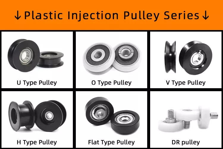
pulley

Types of pulleys

If you are an engineer, you must have come across different types of pulleys. Some pulleys come in multiple types, but a typical pulley has only 1 type. These types of pulleys are used in various industrial processes. Here are some common types of pulleys that engineers encounter on the job. In addition to the above, there are many more. If you haven’t seen them in practice, you can check out a list of the different types below.
Fixed pulleys: Fixed pulleys have a roller attached to a fixed point. The force required to pull the load through the fixed pulley is the same as the force required to lift the object. Movable pulleys allow you to change the direction of the force, for example, by moving it laterally. Likewise, movable pulleys can be used to move heavy objects up and down. Commonly used in multi-purpose elevators, cranes and weight lifters.
Composite pulleys combine fixed and movable pulleys. This combination adds to the mechanical advantage of both systems. It can also change the direction of the force, making it easier to handle large loads. This article discusses the different types of pulleys used for lifting and moving. Braided pulleys are an example of these pulleys. They combine the advantages of both types.
A simple pulley consists of 1 or more wheels, which allow it to reverse the direction of the force used to lift the load. On the other hand, dual-wheel pulleys can help lift twice the weight. By combining multiple materials into 1 pulley, a higher ME will be required. Regardless of the type of pulley, understanding the principles behind it is critical.
Pulleys are an important part of construction and mechanical engineering, and their use dates back to Archimedes. They are a common feature of oil derricks and escalators. The main use of pulleys is to move heavy objects such as boats. In addition to this, they are used in other applications such as extending ladders and lifting heavy objects. The pulley also controls the aircraft rudder, which is important in many different applications.

Commonly used

Common uses for pulleys are varied. Pulley systems are found throughout most areas of the house, from adjustable clotheslines to motor pulleys in different machines. Commercially, 1 of the most common uses is for cranes. Cranes are equipped with pulleys to lift heavy objects. It is also common to use pulley systems in tall buildings, which allow tall buildings to move with relative ease.
Pulleys are commonly used in interception and zipline systems, where a continuous rope around the pulley transmits force. Depending on the application, the rope is either light or strong. Pulleys are formed by wrapping a rope around a set of wheels. The rope pulls the object in the direction of the applied force. Some elevators use this system. Pull a cable on 1 end and attach a counterweight on the other end.
Another common use for pulleys is to move heavy objects. Pulleys mounted on walls, ceilings or other objects can lift heavy objects like heavy toolboxes or 2×4 planks. The device can also be used to transfer power from 1 rotating shaft to another. When used to lift heavy objects, pulleys can be used to help you achieve your goals of a good workout.
Pulley systems have a variety of uses, from the most basic to the most advanced. Its popularity is indisputable and it is used in different industries. A good example is timing belts. These pulleys transmit power to other components in the same direction. They can also be static or dynamic depending on the needs of the machine. In most cases, the pulley system is custom made for the job.
Pulley systems can be simple or complex, but all 3 systems transfer energy efficiently. In most cases, the mechanical advantage of a single pulley is 1 and the mechanical advantage of a single active pulley is 2. On the other hand, a single live pulley only doubles the force. This means you can trade effort for distance. Pulleys are the perfect solution for many common applications.
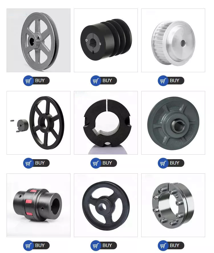
pulley

Safety Notice

If you use pulleys, you need to take some safety precautions. First, make sure you’re wearing the correct protective gear. A hard hat is a must to avoid being hit by falling objects. You may also want to wear gloves for added protection. You should also maintain a good distance from the pulley so that nearby people can walk around it safely.
Another important safety measure to take before using a chain hoist is to barricade the area to be lifted. Use marker lines to prevent the load from sliding when moving horizontally. Finally, use only the sprocket set for vertical lift. Always install shackle pins before lifting. You should also wear personal protective equipment such as earplugs and safety glasses when using the chain hoist.
In addition to these safety measures, you should also use cables made from aerospace-grade nylon. They will last many cycles and are made of high quality materials. Also, make sure the cables are lubricated. These measures reduce friction and corrosion. No matter what industry you are in, be sure to follow these precautions to ensure a long service life for your cables. Consult the cable manufacturer if you are unsure of the appropriate material. A company with 60 years of experience in the cable industry can recommend the right material for your system.

China Standard Centrifugal Water Pump Parts Hf-7c     with high qualityChina Standard Centrifugal Water Pump Parts Hf-7c     with high quality

China OEM Tractor Parts D116020021 with Hot selling

Product Description

(1)High quality with best price. We can make according to your samples or drawing With EPDM, SR ect Materials.


(2)Product performance: High temperature resistance, anti-aging. Excellent physical and mechanical properties, anti-frication property, high elasticity.
 

HOWO
       /   
  AZ9719470045 40   
  WG9157126 80  22*29*370
  WG911253571 250  22*29*150
  WG9100360005 80  22*32*460
  WG910571140 30  22*620
HOWO AZ9725525716/5718  
VOLVO 2 0571 71   
HOWO AZ9725520269   100   
  WG9625531105 30  55*67*320120
HOWO AZ1642430263 400   
  WG9719530308 40  55*65*29084
  WG9719530116/3 30  55*65*34593
  WG9719530115/1 36  55*65*330118
HOWO 199100680066  400   
HOWO WG973571011/1   30  90*185
HOWO A7 AZ9925240002 150   
HOWO A7 AZ9725591571 12   
HOWO A7 WG9925530011 64  76*86*126
HOWO WG9725538202 60   
HOWO WG9725538203 36   
HOWO10 WG9725538238  16  20*30*1500110
09 WG972519 0571 /1 28  106*115*170
09 WG9725190907/1 32  150*168*80
09 WG9725190905/1 30  180*194*75
09 WG9719535717/1 60  100*110*88
09 WG972519571 12  210*222*115
(S) WG912571516/2 20  81*95711*11571
(S) WG9125530150/1 20  80*89100*15710
  WG972519571/2 24  204*214*90
  WG9725190147/1 18  150*135
09 WG9725530142 18  90*98225
  WG9725530190/1 20  90*130305
09 WG9725530058 30  90*213
EGR AZ1557060012 200  55*65*70
EGR AZ1557060013 160  55*65*90
D12/ WG9918530007/1 48  5577*200
A7  WG9925530009/1 50  75*85*200
   WG9625531107/1 70  55*225
A7 AZ1664430095 16   
  WG9725520727/2 20   

What is a pulley?

Pulleys are shafts or wheels on a shaft that support the movement and change of direction of a taut cable. The pulley also transfers power from the shaft to the cable. A simple pulley is used to raise the school flag. Read on to learn about the basic types of pulleys. We also covered the use of pulleys in everyday life. Read on to learn more about this important mechanical part.
pulley

composite pulley

A composite pulley is a mechanical system where 2 or more pulleys and ropes are connected together. It reduces the force required to lift the load because the force is divided by the distance of each pulley. Distance is equal to the mass of the object. Composite pulleys are a common mechanical system on sailboats. Composite pulleys can be used to lift heavy equipment such as sails.
The compound pulley unit consists of 2 pulleys, 1 fixed and the other movable. The fixed pulley is fixed overhead, while the movable pulley is connected to the load by a chain. The lift applies force to the other end of the rope. Anchor points are attached to fixed joists, ceiling joists or sturdy branches. The chain should be long enough to support the load during lifting.
Composite pulleys can be made from a variety of materials. Some are fixed and remain fixed. Others are detachable. The composite pulley combines the advantages of both types, making it a versatile tool. In the table below, these 3 types of pulleys are compared. It’s easy to see which 1 is best for your needs. The right choice depends on your specific needs and budget.
The compound pulley system consists of 2 fixed pulleys and 1 movable pulley. The compound pulley system multiplies the force by a factor of 2. The compound pulley system is particularly suitable for heavy loads and is ideal for construction sites. Workers apply less than half the load force on the composite pulley, significantly reducing the force required. This is a major benefit for many people.

Fixed pulley

Fixed pulleys are fixed gears of fixed length that are mounted on solid objects. There are many different types of pulley systems. Some cooperate with each other, but not “fixed”.
Fixed pulleys can be used for a variety of purposes. One application is to lift small objects. They have a one-to-1 mechanical advantage. Often, a single pulley can lift small loads. The force required to lift a single fixed pulley remains the same. They are usually used to lift lighter objects. They can even be attached to buckets used to draw water from wells.
While single fixed pulleys have desirable mechanical advantages, they are not suitable for force multipliers. Because their mechanical advantage diminishes over time, they are not effective force multipliers. They are used to redirect work so that it can be applied in the most convenient direction. This mechanical advantage is the main advantage of fixed pulleys and the most common way of moving objects. They have several benefits, including the ability to increase the speed of moving objects.
Another application for fixed pulleys is lifting supplies. A scaffold can weigh more than 1 and can be directly hoisted. In order to facilitate the transportation of materials, fixed pulleys are usually installed on the top of the scaffolding on construction sites. Then thread the rope through the edge of the groove that holds the pulley. The fixed pulley exerts the same force on the pull side as on the push side. The same is true for moving objects with fixed pulleys.
pulley

moving pulley

A movable pulley is a device whose part is fixed to another object, usually a rod or beam. The movable part moves with the load, making the load feel lighter. This is a useful tool for those who need to carry heavy items such as large bags. The advantages of moving pulleys are many. Here are some of them. Read on to learn more about them.
One of the most common uses of movable pulley systems is climbing high objects. Climbers act as pulley loads and pull ropes to lift objects. Eventually, when the traction stops, the climber descends. However, it is still a useful tool in other situations. The movable pulley system can help you climb the tallest objects or lift them to level surfaces.
Another example of movable pulleys is in industry. Depending on the load, movable pulleys make handling and moving loads easier. You can use them in a variety of applications in manufacturing and industry, including cleaning. For example, the American flag is raised and lowered every day. Removable pulleys are a handy tool when buildings need cleaning.
If you’re not sure whether a task requires a pulley, a zipline might be a good option. Connect the 2 ends of the rope and the pulley will move along the rope, then attach the rope to the metal cable. The load is the person holding the pulley, and the force comes from the attachment on the other end of the rope. There are 2 types of live pulleys: simple pulleys with just 1 wheel and live pulleys with many ropes attached.

School flag raised with simple pulleys

How is the school flag raised? It is pulled up by a rope attached to a pulley at the top of the pole. When the rope is pulled, the pulley turns, raising the flag. A pulley is a simple mechanism that helps people move heavier objects with ease. The rope must be securely attached to the pulley to keep the flag stable.
A simple pulley is a spinning wheel with grooves on 1 side and ropes on the other. The rope can be any length and the wheels can be any size. The rope has to go through the groove and the load is attached to the other end of the rope. Simple pulleys are pulleys with fixed shafts. An example is the wheel on a school flagpole.
A simple pulley system consists of a primary pole, a secondary pole and an outer member. The primary flagpole is connected to the track by a detour, while the secondary flagpole is connected to the track by a pipe. There is a groove on 1 side of the track, which passes through the inner cavity of the flagpole. An open track at the upper end of the track connects the 2 parts of the pulley.
A simple pulley can be used for many purposes. This is a useful machine that can be used to raise the flag. Among other things, it can be used in clothing lines, bird feeders, and even roofers. And, of course, you can use the pulley to raise the flag. Its versatility makes it an essential part of school decor.
pulley

cast iron pulley

If you are looking for pulleys for your machine, you may come across cast iron pulleys. They are usually cheap and available in a variety of sizes. The rim is held in place by a mesh attached to a central boss. The arms and spokes can be straight or curved, but most are oval. There are many uses for this type of pulley.
You might wonder why the arms of cast iron pulleys are so curved. Bent arms tend to yield rather than break. Cast iron pulleys are usually round with a slight bump on the rim, which helps keep the belt centered on the rim as it moves. On a 300mm diameter pulley, the bumps may be as small as 9mm.

China OEM Tractor Parts D116020021     with Hot sellingChina OEM Tractor Parts D116020021     with Hot selling

China Custom Casting Aluminum Machinery Spare Parts with Hot selling

Product Description

PROCESS


Workshop:
 

Business Range:

parts range: aluminum alloy parts:(A380,ADC12,ADC10,6061,Etc……) 

                      Zinc alloy parts:(ZAMAK3, ZAMAK5 Etc……)

                      Brass alloy parts:(Si9Cu3, Cuzn-37 Etc……)

                      Iron parts: (Nodularc Iron, Ductile Iron Etc……)

                      Etc……

Production Process:

                     Die casting

                     Sand casting

                     Gravity casting

                     Stamping casting

                     Extrusion profile

                     Pressing casting

                     CNC

                     Etc……

Finishing:    E-coated, Powder coated, Anodizing, Painting, Etc……


Product Character: 

-Customized Tool Design Drawings are Available; 

-Molds are carefully machined to the closest tolerance using the latest equipment; 
-The prototype should be created if the customer require; 
-We offer secondary processing such as oil spraying, screen printing, assembly ect. 
-Traceability is maintained from all inspection gages 
-Mold repair and maintenance are also supported internally.


Advantage:


1.more than 20years experience in casting and machining

2.one-stop service,from CZPT design,casting,machining to surface treatment

3.abundant technology force, good condition of production and inspection, 

and perfect after-sales service. 

4:ISO9001,SGS,TS16949 certificate

5:have own quality laboratory,offer CMM inspection,leaking 

test,Spectroscope raw material test.

6:rich experience in exporting,export products to more than 50 countries


Application:

               Machinery, Electrical, Agriculture, Building, Medical,Etc……

Package and Shipping:


Types of agricultural parts

Agricultural parts can be divided into different categories. These components include tractors, moldboard plows, whips and sickles. Some of the different types of agricultural ingredients are listed below. Each of these parts is important for different types of farming. It is important to know the purpose of each and what it does. If you are a farmer or plan to become a farmer, these parts are critical to your operation.
agriculturalparts

Tractor

The first tractor appeared in the 1920s. Ford and International Harvester were among the first companies to produce farm tractors, but the industry has grown rapidly. By the 1920s, hundreds of companies were producing farm tractors. The agricultural depression of the 1930s forced many of these companies out of business. By the 1930s, only 7 companies were major players in the tractor business. Ford produced the largest number of wheeled tractors in the United States between 1930 and 1955.
Some tractors are equipped with various accessories to enhance their performance. These specialized agricultural components are used for a variety of tasks. These include tillage, harvesting, planting and material handling. Tractors vary in horsepower, lift capacity, control and capabilities. Some models also have device mounting options. The downside of this is that if you need to use the tractor for other purposes, you will have to use additional attachments that can damage the tractor.
Modern tractors have a clutch pedal on the gear lever. This allows you to shift quickly without pedaling. Other tractors have a throttle speed button that improves hydraulic flow to the implement. However, the most important component of a tractor is the engine. Tractors must be driven safely because even minor accidents can cause serious damage to farm equipment. While there are many tractors that can operate without these parts, you can find the right tractor for your job.

Shared plows

One of the many uses of shared plows as part of agriculture is to increase the amount of soil in a field. This plow effectively removes compacted soil and lifts weed roots. According to the University of Nebraska-Lincoln Institute for Agriculture and Natural Resources, plowshares are best used in the fall, when weeds are less active and the soil is more fertile.
The basic plowshare can be adjusted by raising or lowering the plowshare to suit runners in the furrow. However, this design is not suitable for breaking up the heavier soils of northern Europe. In the 6th century, however, the advent of the wheel made it possible to use larger moldboards, which increased food production and population growth. Today, farmers in North America have access to a wide variety of moldboard plows.
Agricultural moldboard plows come in 2 basic styles, horse-drawn or tractor-style. Horse-drawn models have 1 bottom, while tractor-pulled moldboard plows have 1 to 14 hydraulically raised bottoms. Other variants include intermediate breakers and twin moldboard plows. Agricultural moldboard plows are often used in the Midwest and elsewhere.

Grass

Grass is used for mowing. The blade is double edged and bolted to the wooden handle. Steel blades are tempered and braced for strength and durability. The blade can be sharpened if necessary. The straw whip is 30 inches long, which can be a good or a bad thing depending on the user’s height. Blades can be sharpened with sandpaper or a file.
The traditional straw whip 32 includes a rear panel and horizontal shelves. It also features a hollow handle with an adapter at the proximal end and a carrying handle at the distal end. The first cable goes to the power supply and goes through the case and handle. After pulling the cable taut, the straw will be firmly attached to the small holder 8.
The suction tube 32 is connected to an electrical connection 47 that powers the device. A battery pack is provided for use away from the tractor. It is a plastic or metal box and consists of 2 parts: a rechargeable battery 67 and a female electrical plug 68. The switch locks in the open position to prevent accidental use. The switch is also equipped with a safety lock button. These 2 components work together to operate the straw.
agriculturalparts

Scythe

Although it is generally believed that the scythe was first developed in Roman times, its actual development may be earlier. Pliny mentioned 2 different types of sickles, Gallic and Roman. The Gallic sickle was the longer of the 2 and was made of mild steel, while the Roman sickle was made of harder, higher carbon steel.
In the past, people cut wheat by hand with a sickle. They replaced scythes and bagging hooks, which required users to bend over to harvest crops. Although they have largely been replaced by tractor machinery, scythes are still used today in parts of Asia and Europe. The sickle can also reach awkward corners, making it more useful in certain types of cuts.
The sickle belt stretches from Europe to the Middle East and the Midwest of the United States and Canada. It also spans most of Russia, the Middle East and North Africa. In the 19th century, Austrian sickle makers dominated the sickle industry. They produced millions of sickles, some dating back to the 1500s. Some of them were exported to India and the former Soviet Union.

Brushcutter

Brushcutters are powerful agricultural tools used primarily for felling and trimming vegetation. These parts are often multifunctional, and some models are even capable of maintaining road edges and ditches. Some models can even trim branches from certain types of trees. Before you buy your own brush cutter, be sure to read the manual carefully and follow the safety rules. For your own safety and the safety of others, please wear a hard hat, eye and hearing protection, padded gloves, long pants, and boots, and keep young children away from work areas.
Brushcutters are usually attached to the tractor via a 3-point linkage system, with the exception of high reach models that are attached to the tractor via fixed stirrups. Additionally, brush cutters often have a balancing mass located opposite the tractor. These agricultural components are complicated to install, but once installed, they remain coupled to the tractor. A brush cutter is a critical piece of equipment on any tractor.
Most brushcutters use hydraulic engines. The power is transmitted mechanically through a PTO (power take-over) mechanism or a cardan shaft, which turns a hydraulic pump. This pump draws hydraulic oil from a special tank and then sends it through a series of distributors to move the arm and the working organ. As a result, the power of the brush cutter is transferred from the tractor to the working organ by a hydraulic engine.
agriculturalparts

Transplanters

Transplanters for agricultural parts are equipment used to plant seedlings into soil. These machines are used in greenhouses and open fields to increase productivity, yield, and the success of harvesting transplanted crops. Transplanters are typically made of steel and are designed to fit seedlings of all shapes and sizes. Buying a used transplanter is a good idea as long as the working parts are in good condition. When considering a used model, you should inspect it for cracks or corrosion and broken parts.
A mechanical transplanter works faster than hand transplanting, but it becomes slower as your quads and back start hurting. Water-wheel transplanters have become popular in recent years. By automatically delivering water into the holes where the transplants are set, water is delivered to the root system without the need for manual intervention. Moreover, water-wheel transplanters save time on watering. John Good, a farmer who uses a water-wheel transplanter, says that speed is no different between a mechanical transplanter and a water-wheel one.

Cultivatorsw

The basic purpose of cultivators is to turn soil and plant matter into a workable form for the crops. Cultivators are used by both large and small farmers. Cultivators for small farming operations are usually self-propelled, but may be drawn behind a tractor. Two-wheel cultivators are typically fixed and powered by couplings, while four-wheel cultivators are attached via a three-point hitch and operated by power take-off. Some cultivators are still drawn behind a draft animal, and the methods are still used in many developing countries.
Cultivators are used in farming to break up soil around a crop. There are 3 different kinds of cultivators: row crop cultivators, disc cultivators, and power cultivators. Row crop cultivators are used to break up soil before planting, while harrows are used to prepare the soil for planting. In both cases, cultivators are used to disturb the soil consistently throughout the working width. In general, cultivating soil improves aeration and disrupts photosynthesis. Moreover, it can decrease water ponding time after heavy rainfall.
Cultivators are important parts of agricultural machinery. They aerate soil, prepare the seedbed, and kill weeds. By disrupting the soil, cultivators are used to evenly distribute chemical applications. Among them, glyphosate is the most common and widely used weed killer. It is safe for farmers to use, and it effectively eliminates most weeds in a single application.

China Custom Casting Aluminum Machinery Spare Parts     with Hot sellingChina Custom Casting Aluminum Machinery Spare Parts     with Hot selling

China Professional CE Approved Pet Bottle Machine Part (temperature adjuster) with Good quality

Product Description

The pet bottle machine part is temperature adjuster for semi automatic blowing machine, which mahcine is can blow 0.2-20L.

TECHNICAL REFERENCE
MACHINE MODLE   JS-20Z JS-20B JS5II-A JS5II-B JS2II -A JS2II-B
PCS/H   90 90 400 700 1700 850
BOTTLE VOLUME L 20 20 5L 2L 2L 2L
Max Caliber MM 55 180 120 90 50 50
MAX.BOTTLE DIAMETER MM 300 300 180 125 90 90
MAX.BOTTLE HEIGHT MM 520 480 350 350 350 350
Max. thickness of mould MM 310-380 310-380 170-260 170-260 120-170 120-170
Mould opening stroke MM 340 340 230 230 130 130
MAIN MACHINE SIZE M 2.8*0.75*2.0 2.8*0.75*2.0 2.0*0.65*1.8 2.0*0.65*1.8 2.0*0.6*1.7 2.0*0.6*1.7
OVEN SIZE M 2.3*0.7*1.8 2.3*0.8*1.8 1.7*0.6*1.5 1.7*0.6*1.5 1.7*0.6*1.5 1.7*0.6*1.5
Main Machine Weight KG 1700 1700 650 650 500 500
Oven Weight KG 400 400 300 300 300 300


How to tell if your driveshaft needs replacing

What is the cause of the unbalanced drive shaft? Unstable U-joint? Your car may make clicking noises while driving. If you can hear it from both sides, it might be time to hand it over to the mechanic. If you’re not sure, read on to learn more. Fortunately, there are many ways to tell if your driveshaft needs replacing.

unbalanced

An unbalanced driveshaft can be the source of strange noises and vibrations in your vehicle. To fix this problem, you should contact a professional. You can try a number of things to fix it, including welding and adjusting the weight. The following are the most common methods. In addition to the methods above, you can use standardized weights to balance the driveshaft. These standardized weights are attached to the shaft by welders.
An unbalanced drive shaft typically produces lateral vibrations per revolution. This type of vibration is usually caused by a damaged shaft, missing counterweights, or a foreign object stuck on the drive shaft. On the other hand, torsional vibrations occur twice per revolution, and they are caused by shaft phase shifts. Finally, critical speed vibration occurs when the RPM of the drive shaft exceeds its rated capacity. If you suspect a driveshaft problem, check the following:
Manually adjusting the imbalance of a drive shaft is not the easiest task. To avoid the difficulty of manual balancing, you can choose to use standardized weights. These weights are fixed on the outer circumference of the drive shaft. The operator can manually position the weight on the shaft with special tools, or use a robot. However, manual balancers have many disadvantages.
air-compressor

unstable

When the angular velocity of the output shaft is not constant, it is unstable. The angular velocity of the output shaft is 0.004 at ph = 29.5 and 1.9 at t = 1.9. The angular velocity of the intermediate shaft is not a problem. But when it’s unstable, the torque applied to it is too much for the machine. It might be a good idea to check the tension on the shaft.
An unstable drive shaft can cause a lot of noise and mechanical vibration. It can lead to premature shaft fatigue failure. CZPT studies the effect of shaft vibration on the rotor bearing system. They investigated the effect of flex coupling misalignment on the vibration of the rotor bearing system. They assume that the vibrational response has 2 components: x and y. However, this approach has limited application in many situations.
Experimental results show that the presence of cracks in the output shaft may mask the unbalanced excitation characteristics. For example, the presence of superharmonic peaks on the spectrum is characteristic of cracks. The presence of cracks in the output shaft masks unbalanced excitation characteristics that cannot be detected in the transient response of the input shaft. Figure 8 shows that the frequency of the rotor increases at critical speed and decreases as the shaft passes the natural frequency.

Unreliable

If you’re having trouble driving your car, chances are you’ve run into an unreliable driveshaft. This type of drivetrain can cause the wheels to stick or not turn at all, and also limit the overall control of the car. Whatever the reason, these issues should be resolved as soon as possible. Here are some symptoms to look for when diagnosing a driveshaft fault. Let’s take a closer look.
The first symptom you may notice is an unreliable drive shaft. You may feel vibrations, or hear noises under the vehicle. Depending on the cause, it could be a broken joint or a broken shaft. The good news is that driveshaft repairs are generally relatively inexpensive and take less time than a complete drivetrain replacement. If you’re not sure what to do, CZPT has a guide to replacing the U-connector.
One of the most common signs of an unreliable driveshaft is clanging and vibration. These sounds can be caused by worn bushings, loose U-joints, or damaged center bearings. This can cause severe vibration and noise. You can also feel these vibrations through the steering wheel or the floor. An unreliable driveshaft is a symptom of a bigger problem.
air-compressor

Unreliable U-joints

A car with an unreliable U-joint on the drive shaft can be dangerous. A bad u-joint can prevent the vehicle from driving properly and may even cause you trouble. Unreliable u-joints are cheap to replace and you should try getting parts from quality manufacturers. Unreliable U-joints can cause the car to vibrate in the chassis or gear lever. This is a sure sign that your car has been neglected in maintenance.
Replacing a U-joint is not a complicated task, but it requires special tools and a lot of elbow grease. If you don’t have the right tools, or you’re unfamiliar with mechanical terminology, it’s best to seek the help of a mechanic. A professional mechanic will be able to accurately assess the problem and propose an appropriate solution. But if you don’t feel confident enough, you can replace your own U-connector by following a few simple steps.
To ensure the vehicle’s driveshaft is not damaged, check the U-joint for wear and lubrication. If the U-joint is worn, the metal parts are likely to rub against each other, causing wear. The sooner a problem is diagnosed, the faster it can be resolved. Also, the longer you wait, the more you lose on repairs.

damaged drive shaft

The driveshaft is the part of the vehicle that connects the wheels. If the driveshaft is damaged, the wheels may stop turning and the vehicle may slow down or stop moving completely. It bears the weight of the car itself as well as the load on the road. So even a slight bend or break in the drive shaft can have dire consequences. Even a piece of loose metal can become a lethal missile if dropped from a vehicle.
If you hear a screeching noise or growl from your vehicle when shifting gears, your driveshaft may be damaged. When this happens, damage to the u-joint and excessive slack in the drive shaft can result. These conditions can further damage the drivetrain, including the front half. You should replace the driveshaft as soon as you notice any symptoms. After replacing the driveshaft, you can start looking for signs of wear.
A knocking sound is a sign of damage to the drive shaft. If you hear this sound while driving, it may be due to worn couplings, damaged propshaft bearings, or damaged U-joints. In some cases, the knocking noise can even be caused by a damaged U-joint. When this happens, you may need to replace the entire driveshaft, requiring a new one.
air-compressor

Maintenance fees

The cost of repairing a driveshaft varies widely, depending on the type and cause of the problem. A new driveshaft costs between $300 and $1,300, including labor. Repairing a damaged driveshaft can cost anywhere from $200 to $300, depending on the time required and the type of parts required. Symptoms of a damaged driveshaft include unresponsiveness, vibration, chassis noise and a stationary car.
The first thing to consider when estimating the cost of repairing a driveshaft is the type of vehicle you have. Some vehicles have more than one, and the parts used to make them may not be compatible with other cars. Even if the same car has 2 driveshafts, the damaged ones will cost more. Fortunately, many auto repair shops offer free quotes to repair damaged driveshafts, but be aware that such work can be complicated and expensive.

China Professional CE Approved Pet Bottle Machine Part (temperature adjuster)     with Good qualityChina Professional CE Approved Pet Bottle Machine Part (temperature adjuster)     with Good quality

China wholesaler Hot Sales 8000mg/H DIY CZPT Parts Used for Smoke and Pet Odors and Musty Smell with Best Sales

Product Description


Specification:

Product Name

8g CZPT generator

Product Weight

0.5kg

Ceramic Plate Size

125x55mm

Ozone Production

8g/hour

Transformer Size

147*55*56mm

Work Temperature

0-40ºC

material

stainless steel

Work Humidity

35%-85%RH


The Usage:
Usage mainly: CZPT sterilization, detoxification, preservation, deodorant, bleaching and so on.
Value:Customer can this CZPT generator to install the CZPT machine 

FAQ
1. who are we?
We are based in ZheJiang , China, start from 2007,sell to North America(00.00%),Northern Europe(00.00%),South Asia(00.00%),Western Europe(00.00%),Eastern Asia(00.00%),Eastern Europe(00.00%). There are total about 11-50 people in our office.

2. how can we guarantee quality?
Always a pre-production sample before mass production;
Always final Inspection before shipment;

3.what can you buy from us?
Ozone Generator,Ozone Generator Parts

4. why should you buy from us not from other suppliers?
We have 12 years of experience in the development and production of CZPT generator and high voltage transformer. We have a 30-year old factory. And passed the ISO9001 certification.

5. what services can we provide?
Accepted Delivery Terms: FOB,CFR,CIF,EXW,FAS,CIP,FCA,CPT,DEQ,DDP,DDU,Express Delivery,DAF,DES;
Accepted Payment Currency:USD,EUR,JPY,CAD,AUD,HKD,GBP,CNY,CHF;
Accepted Payment Type: T/T,L/C,D/P D/A,MoneyGram,Credit Card,PayPal,Western Union,Cash,Escrow;
Language Spoken:English,Chinese


Drive shaft type

The driveshaft transfers torque from the engine to the wheels and is responsible for the smooth running of the vehicle. Its design had to compensate for differences in length and angle. It must also ensure perfect synchronization between its joints. The drive shaft should be made of high-grade materials to achieve the best balance of stiffness and elasticity. There are 3 main types of drive shafts. These include: end yokes, tube yokes and tapered shafts.
air-compressor

tube yoke

Tube yokes are shaft assemblies that use metallic materials as the main structural component. The yoke includes a uniform, substantially uniform wall thickness, a first end and an axially extending second end. The first diameter of the drive shaft is greater than the second diameter, and the yoke further includes a pair of opposing lugs extending from the second end. These lugs have holes at the ends for attaching the axle to the vehicle.
By retrofitting the driveshaft tube end into a tube fork with seat. This valve seat transmits torque to the driveshaft tube. The fillet weld 28 enhances the torque transfer capability of the tube yoke. The yoke is usually made of aluminum alloy or metal material. It is also used to connect the drive shaft to the yoke. Various designs are possible.
The QU40866 tube yoke is used with an external snap ring type universal joint. It has a cup diameter of 1-3/16″ and an overall width of 4½”. U-bolt kits are another option. It has threaded legs and locks to help secure the yoke to the drive shaft. Some performance cars and off-road vehicles use U-bolts. Yokes must be machined to accept U-bolts, and U-bolt kits are often the preferred accessory.
The end yoke is the mechanical part that connects the drive shaft to the stub shaft. These yokes are usually designed for specific drivetrain components and can be customized to your needs. Pat’s drivetrain offers OEM replacement and custom flanged yokes.
If your tractor uses PTO components, the cross and bearing kit is the perfect tool to make the connection. Additionally, cross and bearing kits help you match the correct yoke to the shaft. When choosing a yoke, be sure to measure the outside diameter of the U-joint cap and the inside diameter of the yoke ears. After taking the measurements, consult the cross and bearing identification drawings to make sure they match.
While tube yokes are usually easy to replace, the best results come from a qualified machine shop. Dedicated driveshaft specialists can assemble and balance finished driveshafts. If you are unsure of a particular aspect, please refer to the TM3000 Driveshaft and Cardan Joint Service Manual for more information. You can also consult an excerpt from the TSB3510 manual for information on angle, vibration and runout.
The sliding fork is another important part of the drive shaft. It can bend over rough terrain, allowing the U-joint to keep spinning in tougher conditions. If the slip yoke fails, you will not be able to drive and will clang. You need to replace it as soon as possible to avoid any dangerous driving conditions. So if you notice any dings, be sure to check the yoke.
If you detect any vibrations, the drivetrain may need adjustment. It’s a simple process. First, rotate the driveshaft until you find the correct alignment between the tube yoke and the sliding yoke of the rear differential. If there is no noticeable vibration, you can wait for a while to resolve the problem. Keep in mind that it may be convenient to postpone repairs temporarily, but it may cause bigger problems later.
air-compressor

end yoke

If your driveshaft requires a new end yoke, CZPT has several drivetrain options. Our automotive end yoke inventory includes keyed and non-keyed options. If you need tapered or straight holes, we can also make them for you.
A U-bolt is an industrial fastener that has U-shaped threads on its legs. They are often used to join 2 heads back to back. These are convenient options to help keep drivetrain components in place when driving over rough terrain, and are generally compatible with a variety of models. U-bolts require a specially machined yoke to accept them, so be sure to order the correct size.
The sliding fork helps transfer power from the transfer case to the driveshaft. They slide in and out of the transfer case, allowing the u-joint to rotate. Sliding yokes or “slips” can be purchased separately. Whether you need a new 1 or just a few components to upgrade your driveshaft, 4 CZPT Parts will have the parts you need to repair your vehicle.
The end yoke is a necessary part of the drive shaft. It connects the drive train and the mating flange. They are also used in auxiliary power equipment. CZPT’s drivetrains are stocked with a variety of flanged yokes for OEM applications and custom builds. You can also find flanged yokes for constant velocity joints in our extensive inventory. If you don’t want to modify your existing drivetrain, we can even make a custom yoke for you.

China wholesaler Hot Sales 8000mg/H DIY CZPT Parts Used for Smoke and Pet Odors and Musty Smell     with Best SalesChina wholesaler Hot Sales 8000mg/H DIY CZPT Parts Used for Smoke and Pet Odors and Musty Smell     with Best Sales

China Professional CNC Machining Orange RC Racing Clutch Parts near me manufacturer

Product Description

CNC Machining Orange RC Racing Clutch Parts

About Us:
HangZhou CZPT Hardware products Co., Ltd. is located in HangZhou City, ZheJiang Province of China. We has extremely convenient transportation conditions. 

Established in 2014, our company now covers an area of more than8000 square meters, and have over 100 full time employees. 
We are a professional manufacturer and have 7 years experience in precisely manufacturing and processing machinery parts and components, especially precision CNC machined items. 
We has over 120 units of manufacturing equipments, including CNC lathes, machine centers, grinding machines, etc. We can provide precision machining services, such as CNC milling, turning, drilling, tapping, stamping, anodizing, knurling, die casting, sand casting, and forging. 
We can machine many kinds of materials, including carbon steel, stainless steel, aluminum, brass, bronze, Iron, plastic, etc. 
With advanced technology support and management concepts, CZPT has developed steadily and quickly. Since establishment, we have been cooperating with many domestic and overseas enterprises. Most of our products are shipped to international clients. At present, we have long-term clients from USA, Europe, Middle East, Africa, Japan and Korea. With first-class technology, competitive pricing, superior quality, dependable on-time delivery, and outstanding customer service, we have won the full recognition and high appreciation from our clients. 

*How to receive an online quotation?
Please send us your 3D drawing/2D drawing for us to check all dimension

  1. Specify the required material, finish, quantity information in the email, we will handle it for you once receiving it soon!

Note: Workable 3D Drawing Formats: STEP/IGS/X_T/STL/SOLIDWORKS etc, 2D Drawing with PDF will do.

*Product Description:

Advantages »Reliable CNC service
»Good machining quality
»Reasonable Pricing provided
»Competitive shipping cost service
»MOQ 1PCS and small quantity order accepted
»Professional engineering service when any modification required
»Any turnkey assembly or customized package requirements, we’ll meet your demands!
Equipment

»80 sets of CNC turning machines;

»30 sets of the most technologically advanced machining CNC milling machines;

»30 sets of Multi-Spindle Japan Precision Swiss CNC lathes

RFQ Customer Inquiry →Engineering Communication →Cost Analysis →Sales Analysis →Quote to Customer
» 1-3 Work Days Only
» Submit RFQ with complete commercial terms
Sample Making Sample Order → Engineering Review → Sample Plan to Customer → Sample Status Tracking → Submit Samples with Doc.
» Tooling L/T: 2-4 weeks, Sample L/T: 1 week
» Continuous Sample Status Tracking
» Complete Documents for sample approval
Order Management CRM System → Open Order Confirm → Logistic Arrangement.
» Production L/T: 2-4 wks
» Weekly Open Order Confirm
» Preferred 3PL Service to Customers
Quality Control Certificates: RoHS, ISO9001:2008, SGS.
IQC → IPQC → OQC/FQC → Quality Complain Feedback → Audit & Training.
» Plant Audit and Qualified by world famous company
» Strict Quality Management Procedure with Traceability
Application »Aerospace
»Marine
»Motorbike
»Automotive
»PhotoGear
»EDC Tools
» lighting fittings
»Office equipment
»Home appliance
»Medical equipment
»Telecommunication
»Electrical & Electronics
»Fire detection system, etc.


*What we can offer: 

1).Material capabilities: 
 

Stainless Steel SS201, SS301, SS303, SS304, SS316, SS416 etc.
Steel Mild steel, Carbon steel, 4140, 4340, Q235, Q345B, 20#, 45#, etc. 
Brass HPb63, HPb62, HPb61, HPb59, H59, H62, H68, H80 etc.
Copper C11000, C12000, C12000 C36000 etc.
Aluminum AL6061, Al6063, AL6082, AL7075, AL5052, A380 etc.
Iron A36, 45#, 1213, 12L14, 1215 etc.
Plastic ABS, PC, PE, POM, Delrin, Nylon, Teflon, PP, PEI, Peek etc.

2).Quality control: 
*We have specialized QC testers to check the quality of the products according to different customers’ requirement. Usually, it’s random inspection, and we also offer 100% inspection at a reasonable price if required.
*We have IQC to check the dimensions and surface of the incoming material
*We have PQC to inspect full-course during the manufacturing processing
*We have FQC to inspect all the anodizing/plating and other finishes’ products from our supplier and proceed with the professional quality and appearance inspection before shipping.

3).Surface Finish:anodized finish/ coating/polish/ Passivation/ PVD finish/Plating/brush/heat treatment/fine glass beads/grounding/tumbled finish , etc.

4). Payment terms: T/T payment. The Sample order paid by full payment; Mass production with order amount exceeding can be paid a 50% deposit before production, and balance paid before shipping.

5).Production time: Usually it takes 5~10 working days for sample production; 15~20 working days for mass production days, it depends on your design, simple parts can be produced quickly, the complicated design parts would take us more machining time.

6).Machining capability: 80 sets of the most technologically advanced machining CNC milling machines, 30 sets of CNC turning machines, 30 sets of Multi-Spindle Japan Precision Swiss CNC lathes, and 4 sets of 2D &3D CMM (image measuring instrument) quality control equipment 3 QC staff, enabling CNC Manufacturing to deliver precise parts within the tightest of tolerances, ensuring the highest quality results to meet different customers’ requirements. 

7). Tolerance: +/- 0.02mm (for Metal shaft), +/-0.03mm ( for plastic), for special tolerance requirements, please point them out in the email, we will check if it’s feasible to make it after studying it.

8).Shipping way: 
1) 0-100kg: express&air freight priority, 
2) >100kg: sea freight priority, 
3) As per customized specifications

9). Packing & Delivery: 

1.Packing Detail: Each product packed with plastic preservative, EPE, foam plastic bag, Carton outside, wood case or iron case or as per the customer’s special requirement. Besides, the custom package takes a week to prepare in advance.

2.Delivery Detail: the fast International Shipping time takes 3 ~5 working days by DHL/UPS/FedEx, slow shipping time takes 7~ 8 working days by DHL/UPS/FedEx/TNT, etc

Remark: The products and pictures showed above are only to present the scope of our manufacturing types. We‘re happy to evaluate if we could custom the parts according to your drawings or samples after receiving them.

Send us an email now if any inquiry!


The 5 components of an axle, their function and installation

If you’re considering replacing an axle in your vehicle, you should first understand what it is. It is the component that transmits electricity from 1 part to another. Unlike a fixed steering wheel, the axles are movable. The following article will discuss the 5 components of the half shaft, their function and installation. Hopefully you were able to identify the correct axle for your vehicle. Here are some common problems you may encounter along the way.
Driveshaft

five components

The 5 components of the shaft are flange, bearing surface, spline teeth, spline pitch and pressure angle. The higher the number of splines, the stronger the shaft. The maximum stress that the shaft can withstand increases with the number of spline teeth and spline pitch. The diameter of the shaft times the cube of the pressure angle and spline pitch determines the maximum stress the shaft can withstand. For extreme load applications, use axles made from SAE 4340 and SAE 1550 materials. In addition to these 2 criteria, spline rolling produces a finer grain structure in the material. Cutting the splines reduces the strength of the shaft by 30% and increases stress.
The asymmetric length of the shaft implies different torsional stiffness. A longer shaft, usually the driver’s side, can handle more twist angles before breaking. When the long axis is intact, the short axis usually fails, but this does not always happen. Some vehicles have short axles that permanently break, causing the same failure rate for both. It would be ideal if both shafts were the same length, they would share the same load.
In addition to the spline pitch, the diameter of the shaft spline is another important factor. The small diameter of a spline is the radius at which it resists twisting. Therefore, the splines must be able to absorb shock loads and shocks while returning to their original shape. To achieve these goals, the spline pitch should be 30 teeth or less, which is standard on Chrysler 8.75-inch and GM 12-bolt axles. However, a Ford 8.8-inch axle may have 28 or 31 tooth splines.
In addition to the CV joints, the axles also include CV joints, which are located on each end of the axle. ACV joints, also known as CV joints, use a special type of bearing called a pinion. This is a nut that meshes with the side gear to ensure proper shaft alignment. If you notice a discrepancy, take your car to a shop and have it repaired immediately.

Function

Axles play several important roles in a vehicle. It transfers power from the transmission to the rear differential gearbox and the wheels. The shaft is usually made of steel with cardan joints at both ends. Shaft Shafts can be stationary or rotating. They are all creatures that can transmit electricity and loads. Here are some of their functions. Read on to learn more about axles. Some of their most important features are listed below.
The rear axle supports the weight of the vehicle and is connected to the front axle through the axle. The rear axle is suspended from the body, frame and axle housing, usually spring loaded, to cushion the vehicle. The driveshaft, also called the propshaft, is located between the rear wheels and the differential. It transfers power from the differential to the drive wheels.
The shaft is made of mild steel or alloy steel. The latter is stronger, more corrosion-resistant and suitable for special environments. Forged for large diameter shafts. The cross section of the shaft is circular. While they don’t transmit torque, they do transmit bending moment. This allows the drive train to rotate. If you’re looking for new axles, it’s worth learning more about how they work.
The shaft consists of 3 distinct parts: the main shaft and the hub. The front axle assembly has a main shaft, while the rear axle is fully floating. Axles are usually made of chrome molybdenum steel. The alloy’s chromium content helps the axle maintain its tensile strength even under extreme conditions. These parts are welded into the axle housing.
Driveshaft

Material

The material used to make the axle depends on the purpose of the vehicle. For example, overload shafts are usually made of SAE 4340 or 1550 steel. These steels are high strength low alloy alloys that are resistant to bending and buckling. Chromium alloys, for example, are made from steel and have chromium and molybdenum added to increase their toughness and durability.
The major diameter of the shaft is measured at the tip of the spline teeth, while the minor diameter is measured at the bottom of the groove between the teeth. These 2 diameters must match, otherwise the half shaft will not work properly. It is important to understand that the brittleness of the material should not exceed what is required to withstand normal torque and twisting, otherwise it will become unstable. The material used to make the axles should be strong enough to carry the weight of a heavy truck, but must also be able to withstand torque while still being malleable.
Typically, the shaft is case hardened using an induction process. Heat is applied to the surface of the steel to form martensite and austenite. The shell-core interface transitions from compression to tension, and the peak stress level depends on the process variables used, including heating time, residence time, and hardenability of the steel. Some common materials used for axles are listed below. If you’re not sure which material is best for your axle, consider the following guide.
The axle is the main component of the axle and transmits the transmission motion to the wheels. In addition, they regulate the drive between the rear hub and the differential sun gear. The axle is supported by axle bearings and guided to the path the wheels need to follow. Therefore, they require proper materials, processing techniques and thorough inspection methods to ensure lasting performance. You can start by selecting the material for the shaft.
Choosing the right alloy for the axle is critical. You will want to find an alloy with a low carbon content so it can harden to the desired level. This is an important consideration because the hardenability of the alloy is important to the durability and fatigue life of the axle. By choosing the right alloy, you will be able to minimize these problems and improve the performance of your axle. If you have no other choice, you can always choose an alloy with a higher carbon content, but it will cost you more money.
Driveshaft

Install

The process of installing a new shaft is simple. Just loosen the axle nut and remove the set bolt. You may need to tap a few times to get a good seal. After installation, check the shaft at the points marked “A” and “D” to make sure it is in the correct position. Then, press the “F” points on the shaft flange until the points are within 0.002″ of the runout.
Before attempting to install the shaft, check the bearings to make sure they are aligned. Some bearings may have backlash. To determine the amount of differential clearance, use a screwdriver or clamp lever to check. Unless it’s caused by a loose differential case hub, there shouldn’t be any play in the axle bearings. You may need to replace the differential case if the axles are not mounted tightly. Thread adjusters are an option for adjusting drive gear runout. Make sure the dial indicator is mounted on the lead stud and loaded so that the plunger is at right angles to the drive gear.
To install the axle, lift the vehicle with a jack or crane. The safety bracket should be installed under the frame rails. If the vehicle is on a jack, the rear axle should be in the rebound position to ensure working clearance. Label the drive shaft assemblies and reinstall them in their original positions. Once everything is back in place, use a 2-jaw puller to pry the yoke and flange off the shaft.
If you’ve never installed a half shaft before, be sure to read these simple steps to get it right. First, check the bearing surfaces to make sure they are clean and undamaged. Replace them if they look battered or dented. Next, remove the seal attached to the bushing hole. Make sure the shaft is installed correctly and the bearing surfaces are level. After completing the installation process, you may need to replace the bearing seals.

China Professional CNC Machining Orange RC Racing Clutch Parts     near me manufacturer China Professional CNC Machining Orange RC Racing Clutch Parts     near me manufacturer

China Good quality Agricultural Machinery Parts for John Deere Tractor Clutch Disc with Hot selling

Product Description

FRICTION MATERIAL
Made of special friction material with the original standard, can withstand the harsh environment and ensure the service life

Friction materials from well-known manufacturers

Ceramic copper base & imported material is selected as friction material

Technical Update
Before improvement, there are 8 damping springs with firm structure, small torsion angle, and large stiffness

After improvement, there are 6 damping springs with firm structure, large torsion angle, and small stiffness

Why choose us

* The company was founded in 1998
* The plant covers an area of 7 509 2788       3 RE177574 887889M94
3599462M91 3757103M92 515 4514      514 4741      515 6514 3757111M91
3757111M91
3757115R92 AL 39244
AL 57415
AL 61754
AL 68571 82011592


Packaging Picture

Certificates


FAQ

Q1: Where is the location of OUTAISHI Automotive Parts CO LTD?
A1: Our company locals in HangZhou city, around 800kms from HangZhou, 700kms from ZheJiang , and it is very convenient to travel.
       Only 1.5 hours by air or 4 hours by train from HangZhou or ZheJiang .

Q2: What are the main products of OUTAISHI Automotive Parts CO LTD?
A2: Our main products are clutch assembly, clutch cover, clutch disc, clutch bearing for Automobiles, construction machinery, and tractor.

Q3: What are your terms of packing?
A3: Generally, we pack your goods using brown or white blank neutral boxes. If you have a legally registered patent, we can pack the goods in your branded boxes after getting your authorization letters.

Q4: What are your terms of payment?
A4: T/T 30% as deposit, and 70% before delivery. We’ll show you the photos of the products and packages before you pay the balance.

Q5: How long I can get the goods after confirming the order?
A5: We need 10-50days for production; If you could arrange 100%TT, we will book ship advanced, you don’t need to waste time waiting for delivery.

Q6: Can you produce according to the samples?
A6: Yes, we can produce your samples or technical drawings. We can build the molds and fixtures.

Q7: What is your guarantee?
A7: 1 year or 12000km;

Q8: What should I do if claims appear?
A8: When the claims appear, what we need are the pictures of products, the use condition brief, and the order information. CHALLENWAY will analyze the problem, even field investigation, and work out a final option with customers.

Q9. Do you test all your goods before delivery?
A9: Yes, we have 100% test before delivery

Q10: How do you make our business a long-term and good relationship?
A10:1.We keep good quality and competitive price to ensure our customers benefit ;
        2. We respect every customer as our friend and we sincerely do business and make friends with them, no matter where they come from.


How to tell if your driveshaft needs replacing

What is the cause of the unbalanced drive shaft? Unstable U-joint? Your car may make clicking noises while driving. If you can hear it from both sides, it might be time to hand it over to the mechanic. If you’re not sure, read on to learn more. Fortunately, there are many ways to tell if your driveshaft needs replacing.

unbalanced

An unbalanced driveshaft can be the source of strange noises and vibrations in your vehicle. To fix this problem, you should contact a professional. You can try a number of things to fix it, including welding and adjusting the weight. The following are the most common methods. In addition to the methods above, you can use standardized weights to balance the driveshaft. These standardized weights are attached to the shaft by welders.
An unbalanced drive shaft typically produces lateral vibrations per revolution. This type of vibration is usually caused by a damaged shaft, missing counterweights, or a foreign object stuck on the drive shaft. On the other hand, torsional vibrations occur twice per revolution, and they are caused by shaft phase shifts. Finally, critical speed vibration occurs when the RPM of the drive shaft exceeds its rated capacity. If you suspect a driveshaft problem, check the following:
Manually adjusting the imbalance of a drive shaft is not the easiest task. To avoid the difficulty of manual balancing, you can choose to use standardized weights. These weights are fixed on the outer circumference of the drive shaft. The operator can manually position the weight on the shaft with special tools, or use a robot. However, manual balancers have many disadvantages.
air-compressor

unstable

When the angular velocity of the output shaft is not constant, it is unstable. The angular velocity of the output shaft is 0.004 at ph = 29.5 and 1.9 at t = 1.9. The angular velocity of the intermediate shaft is not a problem. But when it’s unstable, the torque applied to it is too much for the machine. It might be a good idea to check the tension on the shaft.
An unstable drive shaft can cause a lot of noise and mechanical vibration. It can lead to premature shaft fatigue failure. CZPT studies the effect of shaft vibration on the rotor bearing system. They investigated the effect of flex coupling misalignment on the vibration of the rotor bearing system. They assume that the vibrational response has 2 components: x and y. However, this approach has limited application in many situations.
Experimental results show that the presence of cracks in the output shaft may mask the unbalanced excitation characteristics. For example, the presence of superharmonic peaks on the spectrum is characteristic of cracks. The presence of cracks in the output shaft masks unbalanced excitation characteristics that cannot be detected in the transient response of the input shaft. Figure 8 shows that the frequency of the rotor increases at critical speed and decreases as the shaft passes the natural frequency.

Unreliable

If you’re having trouble driving your car, chances are you’ve run into an unreliable driveshaft. This type of drivetrain can cause the wheels to stick or not turn at all, and also limit the overall control of the car. Whatever the reason, these issues should be resolved as soon as possible. Here are some symptoms to look for when diagnosing a driveshaft fault. Let’s take a closer look.
The first symptom you may notice is an unreliable drive shaft. You may feel vibrations, or hear noises under the vehicle. Depending on the cause, it could be a broken joint or a broken shaft. The good news is that driveshaft repairs are generally relatively inexpensive and take less time than a complete drivetrain replacement. If you’re not sure what to do, CZPT has a guide to replacing the U-connector.
One of the most common signs of an unreliable driveshaft is clanging and vibration. These sounds can be caused by worn bushings, loose U-joints, or damaged center bearings. This can cause severe vibration and noise. You can also feel these vibrations through the steering wheel or the floor. An unreliable driveshaft is a symptom of a bigger problem.
air-compressor

Unreliable U-joints

A car with an unreliable U-joint on the drive shaft can be dangerous. A bad u-joint can prevent the vehicle from driving properly and may even cause you trouble. Unreliable u-joints are cheap to replace and you should try getting parts from quality manufacturers. Unreliable U-joints can cause the car to vibrate in the chassis or gear lever. This is a sure sign that your car has been neglected in maintenance.
Replacing a U-joint is not a complicated task, but it requires special tools and a lot of elbow grease. If you don’t have the right tools, or you’re unfamiliar with mechanical terminology, it’s best to seek the help of a mechanic. A professional mechanic will be able to accurately assess the problem and propose an appropriate solution. But if you don’t feel confident enough, you can replace your own U-connector by following a few simple steps.
To ensure the vehicle’s driveshaft is not damaged, check the U-joint for wear and lubrication. If the U-joint is worn, the metal parts are likely to rub against each other, causing wear. The sooner a problem is diagnosed, the faster it can be resolved. Also, the longer you wait, the more you lose on repairs.

damaged drive shaft

The driveshaft is the part of the vehicle that connects the wheels. If the driveshaft is damaged, the wheels may stop turning and the vehicle may slow down or stop moving completely. It bears the weight of the car itself as well as the load on the road. So even a slight bend or break in the drive shaft can have dire consequences. Even a piece of loose metal can become a lethal missile if dropped from a vehicle.
If you hear a screeching noise or growl from your vehicle when shifting gears, your driveshaft may be damaged. When this happens, damage to the u-joint and excessive slack in the drive shaft can result. These conditions can further damage the drivetrain, including the front half. You should replace the driveshaft as soon as you notice any symptoms. After replacing the driveshaft, you can start looking for signs of wear.
A knocking sound is a sign of damage to the drive shaft. If you hear this sound while driving, it may be due to worn couplings, damaged propshaft bearings, or damaged U-joints. In some cases, the knocking noise can even be caused by a damaged U-joint. When this happens, you may need to replace the entire driveshaft, requiring a new one.
air-compressor

Maintenance fees

The cost of repairing a driveshaft varies widely, depending on the type and cause of the problem. A new driveshaft costs between $300 and $1,300, including labor. Repairing a damaged driveshaft can cost anywhere from $200 to $300, depending on the time required and the type of parts required. Symptoms of a damaged driveshaft include unresponsiveness, vibration, chassis noise and a stationary car.
The first thing to consider when estimating the cost of repairing a driveshaft is the type of vehicle you have. Some vehicles have more than one, and the parts used to make them may not be compatible with other cars. Even if the same car has 2 driveshafts, the damaged ones will cost more. Fortunately, many auto repair shops offer free quotes to repair damaged driveshafts, but be aware that such work can be complicated and expensive.

China Good quality Agricultural Machinery Parts for John Deere Tractor Clutch Disc     with Hot sellingChina Good quality Agricultural Machinery Parts for John Deere Tractor Clutch Disc     with Hot selling

China OEM Omph500 CZPT Hydraulic Motor Parts for Radish Harvesting Machine near me shop

Product Description

OMPH series motor are small volume,; economical type,; which is designed with shaft distribution flow,; which adapt the
Gerotor gear set design and provide compact volume,; high power and low weight.;
OMPH characteristic features:;
        *Small volume,; high efficiency and long life.;
        *Shaft seal can bear high pressure of back and the motor can be used in parallel or in series.;
        *Advanced construction design,; high power and low weight.;

Product Name OMPH500 hyraulic motor
Brand Blince
Shaft key woodruff key,; parallel key,;
Displacement omph36/50/80/100/125/160/200/250/315/400/500
Max.;speed(cont.;); 150rpm
Max.;torque(cont.;); 560N.;m
Max.;pressure(cont.;); 9MPa
Shaft type Cylindrical shaft,; Splined SAE,; Cone-shaft

Our company
Blince company was found in 2004,; HangZhou CZPT Machinery & Electronics Co.;,; Ltd.; specializing in the business of hydraulic motor,; cycloid motor,; vane pump and hydraulic valve.; Located in Changan,; HangZhou,; ZheJiang ,; we enjoy convenient access to major transportation networks.; Our company covers an area of 30,;000 square meters and has around 361 people staff members.; Furthermore,; all our products are manufactured with advanced equipment and strict QC procedures in order to ensure high quality.; With stable and timely supply,; credible quality and sincere service,; our products sell well in both domestic and overseas markets.; If you are interested in any of our products,; or wish to place a customized order,;please contact us.; We will do our best to meet your needs .;

Blince hydraulic motor advantage:;
1.;Special dynamic seal can bear high back pressure
2.;Variety mounting of flange,; output shaft,; and port.;
3.;Small volume,; smart structure
4.;Low leakage,; no noisy
 

Application
Hydraulic motors are widely applied in agriculture machinery,; fishing machinery,; plastic industry,; mining,; and
construction machinery,; especially fitted to lower load applications,; such as plastic injection mold machine,; cleaner,;
grass cutter,; etc.;

Packing
Packaging Details:; Each piece wrapped in a poly bag and carton,;straightly stand on iron shelf.;
1.; Industrial packing:; plastic tube +carton+wooden pallets
2.; Commercial packing:; plastic bag +color box+wooden pallets
3.; The transportation as per your request
Delivery Detail:; 25 days after the order confirmed
 

Warranty
1.; Guarantee for 1 year or 1000 hours (according to whichever ends first); from the purchasing date on.;    
2.; During the guarantee period,; our company will provide the free easy-damaged spare parts  for problems caused by our quality of production or raw material.;
3.; After expiration,; our company provides cost spare-parts maintenance for engines.;
Tips:;  Our CZPT also have the core of hydraulic pumps to sell .; If there is a problem with our pump decades later ,; you can replace it by yourself :;);  

FAQ
1.; You are a manufacture or trade company ? 
 We are a manufacture also trade company.;
2.;What certification you can provide?
A:;ISO9001:;2008 B:;CE  C:;CNAS  D:;IAF
3:; How many staff ? 
About 20 salesman in my international sales team
4:;How long your warranty ? (How many years your hydraulic motor can use?);
7-8 years 
5.;How to choice right model of hydraulic motor? 
Pls tell me all your requirement,; our professional engineer will match for you.;
6:;How contact us?
Pls check and save my contact information! Thanks!


The Benefits of Using Self-Lubricating Bushings for Your Next Pivot

Like any other auto part, control arm bushings wear out over time. This results in an increase in irritating vibrations that can be dangerous in severe cases. The bushings in the control arms also wear out due to the stress that extreme driving conditions put on the control arms. Additionally, environmental factors and oversized tires tend to transmit more vibration through the bushing than conventionally sized tires. Whatever the cause, bushings can be the source of many problems.
bushing

wear and cracking

The main cause of dry valve side bushing cracking is a mismatch in thermal expansion of the core and flange. This situation can seriously compromise the safety of the power system. To improve the safety of dry valve side bushings, the crack development of epoxy impregnated paper under various conditions was investigated. A coupled thermomechanical simulation model was also used to study the cracking process.
The first step in diagnosing the cause of bushing wear and cracking is a visual inspection. The bushing of the lower control arm is fixed to the frame by a bracket. If there are any visible cracks, it’s time to replace the bushing. However, there is no need to replace the entire suspension. In some cases, worn bushings can cause a variety of problems, including body lean, excessive tire wear and cornering noise.

Maintenance free

If you’re considering maintenance-free bushings for your next pivot, you’ll be wondering what to look for in these components. The bushing protects the housing from corrosion and keeps the bushing under pressure. However, many users are not familiar with what these components can do for their applications. In this article, we’ll look at several examples of truly maintenance-free pivots and discuss their requirements.
One of the most popular types of maintenance-free bushings are flanged and parallel. Unlike worm gear bushings, these self-lubricating metal bearings are ideal for a variety of applications and conditions. They reduce failure and downtime costs while providing the long-term lubrication required by other types of bushings. Since these sleeves are made of lead-free material, they are RoHS compliant, which means they are environmentally friendly.Another common maintenance-free bushing is plastic. This material is easier to find off-the-shelf and relatively inexpensive to produce. However, it is not suitable for high load applications as it will crack under heavy loads and damage mating parts. Plastics can also deviate if the manufacturing process is imprecise. Plastic bushings can also crack when subjected to high loads.
bushing

self-lubricating

When using a self-lubricating bushing, there is no need to apply grease to the bushing. Oily liquids tend to attract dirt and grit, which can wear away the graphite prematurely. By eliminating the need for regular lubrication, you will reduce equipment maintenance costs. This article will explore the benefits of self-lubricating bushings. You will love your kindness.
Self-lubricating bushings have a strong base material to withstand radial bearing pressure while providing shaft support at the contact surfaces. The material also has good fatigue properties and low friction motion. Self-lubricating bushings can be used in environments with high temperatures and aggressive media. These products can also withstand enormous pressure. When using self-lubricating bushings, it is important to select the correct material.
The main advantage of using self-lubricating bushings is ease of maintenance. They don’t require oil to run and are cheaper to buy. Their main benefit is that they can significantly reduce your machine running costs. These bearings do not require oiling operations, reducing maintenance costs. These bearings also offer a simplified mechanical design due to their thin walls and high load capacity. In addition, they reduce noise levels while maintaining excellent wear resistance. Plus, their materials are ROHS compliant, which means they don’t require oil.
Hydropower installations are another area where self-lubricating bushings have proven their advantages. They reduce maintenance costs, extend equipment life, and improve environmental benefits. For example, the Newfoundland Power Company uses self-lubricating bushings in the gates of its hydroelectric power plants. These self-lubricating bushings eliminate grease from entering waterways and tailraces. As a result, power companies are able to reduce maintenance and costs.

compared to cartilage in the human body

What is the difference between tendon, bone and cartilage? Human cartilage is composed of collagen and elastic fibers. In contrast, fibrocartilage contains more collagen than hyaline cartilage. Both cartilage types are composed of proteoglycans, which have a protein backbone and glycosaminoglycan side chains. These components work together to provide structure and flexibility to the cartilage.
Bone is a combination of living and dead cells embedded in a matrix. The outer hard layer of bone is dense bone, and the inner layer is spongy, containing bone marrow, blood vessels, nerves, etc. Bone contains both organic and inorganic substances, and this process of hardening of the matrix produces bone. On the other hand, cartilage consists of chondrocytes and a matrix composed of collagen and elastin fibers. Compared to bone, cartilage is yellow and contains elastic fibers.
Although bone and cartilage are structurally identical, cartilage is more flexible. It is mainly found in the joints and respiratory system and requires flexibility. Its ingredients include collagen and proteoglycans, which provide compression and abrasion resistance. Furthermore, connective tissue is composed of cells, fibers and matrix.
The basic substance of cartilage is chondroitin sulfate, which is derived from animals. Although cartilage grows more slowly than bone, its microstructure is less organized. There is a fibrous sheath covering the cartilage, called the perichondrium. The molecular composition of the ECM plays an important role in the function of cartilage. The collagen matrix is ​​important for cartilage remodeling and consists of changes in the collagen matrix.
bushing

Compared to metal-on-bone contact

Both metal-on-bone contact are known to cause a significant increase in the pressures in a joint. To compare the two, we first calculated the joint contact pressures in each model and compared them. The results of this study support previous research on this subject. The following sections discuss the benefits of both types of contact. They also outline some key differences between the two.

China OEM Omph500 CZPT Hydraulic Motor Parts for Radish Harvesting Machine     near me shop China OEM Omph500 CZPT Hydraulic Motor Parts for Radish Harvesting Machine     near me shop

China best Orange/Yellow/Dark Red Rubber Sealing Parts near me supplier

Product Description

Details:

Product Name rubber product
Material NR,NBR,SBR,EPDM,etc
Applications pipes,industrial,toilets,machinery,,electrial,auto parts,household,etc
Size According to drawing
certificaton ISO9001:2015
Color natural,black,yellow,redor as  per client’s samples or requirements
Shape caple of all shapes as per drawing
Hardness 20ºC~90ºC Shore A,usually 30ºC~80ºC Shore A
Delivery time 20-30after payment received
MQQ 1000pcs
Temperature -40ºC~+230ºC
Free sample Yes
Package As your request
Market Europe,America,Ocenia
QC Every order production will get more than 10 times regular tests and 5times random check by our professional QC.Or by Third Party appointed by customer.

Mold Molding process injection molding,mold processing,extruson
Mould type processing mold,injection mold,extrusion mold
Machines  350T vacuum pressing machine at 300T , 250T and so on
Tooling equipment rubber tension tester,Rubber vulcanization instrument,Durometer,calipers,ageing oven
Cavity 1~400 cavities
Mould life 300,000~1,00,000 times

production Production capacity finish each mold of product in 2.5 minutes and working on 2 shafts with 24 hours
Mold lead time 10~30 Days
Sample lead time 3~5 days
Production time Usually 10~30Days,should be confirmed before order
Loading port ZheJiang

Company Information:

Factory and Equipment:

Certificate:

FAQ
1.Are you manufacture or trading company? 
We are manufacturer.

 2.How to get the fastest quotation?
Send an email with drawing directly.

3.How to get qutation  without drawing?
Possible send sample,pictures or detail descriptions of products to us,we will return drawing for confirm.

4.How about samples?
Free samples is available for your quality,but you should pay the freight.Regarding customise products,sample and CZPT order will go first before mass production.

Why choose us

1. we are the manufacturer of rubber products

2. we have 20 years experience of making silicone daily use products

3. we have a group of experienced and skillful workers

4. our products adopt the most popular element and the best material

5. best service and prompt delivery

6. we offer various colors,styles,size to meet your needs
 

Synthesis of Epicyclic Gear Trains for Automotive Automatic Transmissions

In this article, we will discuss the synthesis of epicyclic gear trains for automotive automatic transmissions, their applications, and cost. After you have finished reading, you may want to do some research on the technology yourself. Here are some links to further reading on this topic. They also include an application in hybrid vehicle transmissions. Let’s look at the basic concepts of epicyclic gear trains. They are highly efficient and are a promising alternative to conventional gearing systems.
Gear

Synthesis of epicyclic gear trains for automotive automatic transmissions

The main purpose of automotive automatic transmissions is to maintain engine-drive wheel balance. The kinematic structure of epicyclic gear trains (EGTs) is derived from graph representations of these gear trains. The synthesis process is based on an algorithm that generates admissible epicyclic gear trains with up to 10 links. This algorithm enables designers to design auto gear trains that have higher performance and better engine-drive wheel balance.
In this paper, we present a MATLAB optimization technique for determining the gear ratios of epicyclic transmission mechanisms. We also enumerate the number of teeth for all gears. Then, we estimate the overall velocity ratios of the obtained EGTs. Then, we analyze the feasibility of the proposed epicyclic gear trains for automotive automatic transmissions by comparing their structural characteristics.
A six-link epicyclic gear train is depicted in the following functional diagram. Each link is represented by a double-bicolor graph. The numbers on the graph represent the corresponding links. Each link has multiple joints. This makes it possible for a user to generate different configurations for each EGT. The numbers on the different graphs have different meanings, and the same applies to the double-bicolor figure.
In the next chapter of this article, we discuss the synthesis of epicyclic gear trains for automotive automatic transaxles. SAE International is an international organization of engineers and technical experts with core competencies in aerospace and automotive. Its charitable arm, the SAE Foundation, supports many programs and initiatives. These include the Collegiate Design Series and A World In Motion(r) and the SAE Foundation’s A World in Motion(r) award.
Gear

Applications

The epicyclic gear system is a type of planetary gear train. It can achieve a great speed reduction in a small space. In cars, epicyclic gear trains are often used for the automatic transmission. These gear trains are also useful in hoists and pulley blocks. They have many applications in both mechanical and electrical engineering. They can be used for high-speed transmission and require less space than other types of gear trains.
The advantages of an epicyclic gear train include its compact structure, low weight, and high power density. However, they are not without disadvantages. Gear losses in epicyclic gear trains are a result of friction between gear tooth surfaces, churning of lubricating oil, and the friction between shaft support bearings and sprockets. This loss of power is called latent power, and previous research has demonstrated that this loss is tremendous.
The epicyclic gear train is commonly used for high-speed transmissions, but it also has a small footprint and is suitable for a variety of applications. It is used as differential gears in speed frames, to drive bobbins, and for the Roper positive let-off in looms. In addition, it is easy to fabricate, making it an excellent choice for a variety of industrial settings.
Another example of an epicyclic gear train is the planetary gear train. It consists of 2 gears with a ring in the middle and the sun gear in the outer ring. Each gear is mounted so that its center rotates around the ring of the other gear. The planet gear and sun gear are designed so that their pitch circles do not slip and are in sync. The planet gear has a point on the pitch circle that traces the epicycloid curve.
This gear system also offers a lower MTTR than other types of planetary gears. The main disadvantage of these gear sets is the large number of bearings they need to run. Moreover, planetary gears are more maintenance-intensive than parallel shaft gears. This makes them more difficult to monitor and repair. The MTTR is also lower compared to parallel shaft gears. They can also be a little off on their axis, causing them to misalign or lose their efficiency.
Another example of an epicyclic gear train is the differential gear box of an automobile. These gears are used in wrist watches, lathe machines, and automotives to transmit power. In addition, they are used in many other applications, including in aircrafts. They are quiet and durable, making them an excellent choice for many applications. They are used in transmission, textile machines, and even aerospace. A pitch point is the path between 2 teeth in a gear set. The axial pitch of 1 gear can be increased by increasing its base circle.
An epicyclic gear is also known as an involute gear. The number of teeth in each gear determines its rate of rotation. A 24-tooth sun gear produces an N-tooth planet gear with a ratio of 3/2. A 24-tooth sun gear equals a -3/2 planet gear ratio. Consequently, the epicyclic gear system provides high torque for driving wheels. However, this gear train is not widely used in vehicles.
Gear

Cost

The cost of epicyclic gearing is lower when they are tooled rather than manufactured on a normal N/C milling machine. The epicyclic carriers should be manufactured in a casting and tooled using a single-purpose machine that has multiple cutters to cut the material simultaneously. This approach is widely used for industrial applications and is particularly useful in the automotive sector. The benefits of a well-made epicyclic gear transmission are numerous.
An example of this is the planetary arrangement where the planets orbit the sun while rotating on its shaft. The resulting speed of each gear depends on the number of teeth and the speed of the carrier. Epicyclic gears can be tricky to calculate relative speeds, as they must figure out the relative speed of the sun and the planet. The fixed sun is not at zero RPM at mesh, so the relative speed must be calculated.
In order to determine the mesh power transmission, epicyclic gears must be designed to be able to “float.” If the tangential load is too low, there will be less load sharing. An epicyclic gear must be able to allow “float.” It should also allow for some tangential load and pitch-line velocities. The higher these factors, the more efficient the gear set will be.
An epicyclic gear train consists of 2 or more spur gears placed circumferentially. These gears are arranged so that the planet gear rolls inside the pitch circle of the fixed outer gear ring. This curve is called a hypocycloid. An epicyclic gear train with a planet engaging a sun gear is called a planetary gear train. The sun gear is fixed, while the planet gear is driven.
An epicyclic gear train contains several meshes. Each gear has a different number of meshes, which translates into RPM. The epicyclic gear can increase the load application frequency by translating input torque into the meshes. The epicyclic gear train consists of 3 gears, the sun, planet, and ring. The sun gear is the center gear, while the planets orbit the sun. The ring gear has several teeth, which increases the gear speed.
Another type of epicyclic gear is the planetary gearbox. This gear box has multiple toothed wheels rotating around a central shaft. Its low-profile design makes it a popular choice for space-constrained applications. This gearbox type is used in automatic transmissions. In addition, it is used for many industrial uses involving electric gear motors. The type of gearbox you use will depend on the speed and torque of the input and output shafts.

China best Orange/Yellow/Dark Red Rubber Sealing Parts     near me supplier China best Orange/Yellow/Dark Red Rubber Sealing Parts     near me supplier

China manufacturer 48″ Lawn Tractor Deck Ayp 174356 Spindle Assembly Shaft 175147 Part with Free Design Custom

Product Description

48″ Spindle Shaft with Bearings and grease fitting Replacement For 174356, 532174356 Spindle Assembly

Fits Craftsman, Hus qvarna, 48″ Decks  
Oregon  85-040
spindle AYP 174356,shaft #175147
Husq varna-
Husq varna–532174356

Mounting Holes Are Tapped (mounting bolts included), Also Includes Blade Bolt (174365) Pulley Locknut (178342) and Spacer (129963 or 187690)

OTHER CRAFTSMAN LAWN TRACTOR 48″ KIT PARTS
3 SPINDLE ASSEMBLIES AYP
SPINDLE ASSEMBLY . SPINDLE SHAFT FITS 48 In. DECKS BUILT AFTER 2
AYP/ROPER/SEARS 532174356
 
3 BLADES AYP 16-5/8In.X 5POINT STAR MULCHER
MULCHING BLADE FOR 48 In. CUT.
WIDTH:2-1/2″
THICKNESS:0.2040″
LENGTH:16-5/8″
REPLACES:
AYP/ROPER/SEARS 173921
AYP/ROPER/SEARS 532173921

1 SPLINED DECK PULLEY

SPLINED PULLEY 4-7/8 In. DIA. FITS 48 In. DECKS.

ID:5/8″
OD:4-7/8″

REPLACES:
AYP/ROPER/SEARS 174375
AYP/ROPER/SEARS 53215711
AYP/ROPER/SEARS 532174375
AYP/ROPER/SEARS 539-15711
1 PULLEY IDLER FLAT 3/8In. X 3-7/8In.
FLAT IDLER PULLEY. FITS 48 In. DECKS FROM 2
AYP/ROPER/SEARS 193197
AYP/ROPER/SEARS 532177968
HUS QVARNA -68
HUS QVARNA -97

1 PULLEY IDLER FLAT 3/8In. X 4-1/2In.

FLAT IDLER PULLEY. FITS: 48 In. DECKS FROM 2
AYP/ROPER/SEARS 532175820
HUs QVARNA -20
1 BELT DECK 5/8In.X 90In. 

PRIMARY DECK BELT.  FITS 48 In. RIDERS. POLYESTER CORD CONSTRUCTION.

LENGTH:90″
WIDTH:5/8″

REPLACES:
AYP/ROPER/SEARS 174368
AYP/ROPER/SEARS 532174368
HUSQ VARNA -68

BELT DECK 5/8In.X 89In.
SECONDARY DECK BELT.  FITS AYP & POXIHU (WEST LAKE) DIS. PRO UNITS. POLYESTER CORD CONSTRUCTION.
LENGTH:89″
WIDTH:5/8″

REPLACES:
AYP/ROPER/SEARS 174369
AYP/ROPER/SEARS 180808
AYP/ROPER/SEARS 532180808
HUSQ VARNA -71
HUSQ VARNA -69
HUSQ VARNA 532180808
SCREW HEX HEAD SELF-TAPPING 5/16In.-18X1In.
THREAD SIZE:5/16-18″
THREAD LENGTH:1″

Worm Shafts and Gearboxes

If you have a gearbox, you may be wondering what the best Worm Shaft is for your application. There are several things to consider, including the Concave shape, Number of threads, and Lubrication. This article will explain each factor and help you choose the right Worm Shaft for your gearbox. There are many options available on the market, so don’t hesitate to shop around. If you are new to the world of gearboxes, read on to learn more about this popular type of gearbox.
worm shaft

Concave shape

The geometry of a worm gear varies considerably depending on its manufacturer and its intended use. Early worms had a basic profile that resembled a screw thread and could be chased on a lathe. Later, tools with a straight sided g-angle were developed to produce threads that were parallel to the worm’s axis. Grinding was also developed to improve the finish of worm threads and minimize distortions that occur with hardening.
To select a worm with the proper geometry, the diameter of the worm gear must be in the same unit as the worm’s shaft. Once the basic profile of the worm gear is determined, the worm gear teeth can be specified. The calculation also involves an angle for the worm shaft to prevent it from overheating. The angle of the worm shaft should be as close to the vertical axis as possible.
Double-enveloping worm gears, on the other hand, do not have a throat around the worm. They are helical gears with a straight worm shaft. Since the teeth of the worm are in contact with each other, they produce significant friction. Unlike double-enveloping worm gears, non-throated worm gears are more compact and can handle smaller loads. They are also easy to manufacture.
The worm gears of different manufacturers offer many advantages. For instance, worm gears are 1 of the most efficient ways to increase torque, while lower-quality materials like bronze are difficult to lubricate. Worm gears also have a low failure rate because they allow for considerable leeway in the design process. Despite the differences between the 2 standards, the overall performance of a worm gear system is the same.
The cone-shaped worm is another type. This is a technological scheme that combines a straight worm shaft with a concave arc. The concave arc is also a useful utility model. Worms with this shape have more than 3 contacts at the same time, which means they can reduce a large diameter without excessive wear. It is also a relatively low-cost model.
worm shaft

Thread pattern

A good worm gear requires a perfect thread pattern. There are a few key parameters that determine how good a thread pattern is. Firstly, the threading pattern must be ACME-threaded. If this is not possible, the thread must be made with straight sides. Then, the linear pitch of the “worm” must be the same as the circular pitch of the corresponding worm wheel. In simple terms, this means the pitch of the “worm” is the same as the circular pitch of the worm wheel. A quick-change gearbox is usually used with this type of worm gear. Alternatively, lead-screw change gears are used instead of a quick-change gear box. The pitch of a worm gear equals the helix angle of a screw.
A worm gear’s axial pitch must match the circular pitch of a gear with a higher axial pitch. The circular pitch is the distance between the points of teeth on the worm, while the axial pitch is the distance between the worm’s teeth. Another factor is the worm’s lead angle. The angle between the pitch cylinder and worm shaft is called its lead angle, and the higher the lead angle, the greater the efficiency of a gear.
Worm gear tooth geometry varies depending on the manufacturer and intended use. In early worms, threading resembled the thread on a screw, and was easily chased using a lathe. Later, grinding improved worm thread finishes and minimized distortions from hardening. As a result, today, most worm gears have a thread pattern corresponding to their size. When selecting a worm gear, make sure to check for the number of threads before purchasing it.
A worm gear’s threading is crucial in its operation. Worm teeth are typically cylindrical, and are arranged in a pattern similar to screw or nut threads. Worm teeth are often formed on an axis of perpendicular compared to their parallel counterparts. Because of this, they have greater torque than their spur gear counterparts. Moreover, the gearing has a low output speed and high torque.

Number of threads

Different types of worm gears use different numbers of threads on their planetary gears. A single threaded worm gear should not be used with a double-threaded worm. A single-threaded worm gear should be used with a single-threaded worm. Single-threaded worms are more effective for speed reduction than double-threaded ones.
The number of threads on a worm’s shaft is a ratio that compares the pitch diameter and number of teeth. In general, worms have 1,2,4 threads, but some have three, five, or six. Counting thread starts can help you determine the number of threads on a worm. A single-threaded worm has fewer threads than a multiple-threaded worm, but a multi-threaded worm will have more threads than a mono-threaded planetary gear.
To measure the number of threads on a worm shaft, a small fixture with 2 ground faces is used. The worm must be removed from its housing so that the finished thread area can be inspected. After identifying the number of threads, simple measurements of the worm’s outside diameter and thread depth are taken. Once the worm has been accounted for, a cast of the tooth space is made using epoxy material. The casting is moulded between the 2 tooth flanks. The V-block fixture rests against the outside diameter of the worm.
The circular pitch of a worm and its axial pitch must match the circular pitch of a larger gear. The axial pitch of a worm is the distance between the points of the teeth on a worm’s pitch diameter. The lead of a thread is the distance a thread travels in 1 revolution. The lead angle is the tangent to the helix of a thread on a cylinder.
The worm gear’s speed transmission ratio is based on the number of threads. A worm gear with a high ratio can be easily reduced in 1 step by using a set of worm gears. However, a multi-thread worm will have more than 2 threads. The worm gear is also more efficient than single-threaded gears. And a worm gear with a high ratio will allow the motor to be used in a variety of applications.
worm shaft

Lubrication

The lubrication of a worm gear is particularly challenging, due to its friction and high sliding contact force. Fortunately, there are several options for lubricants, such as compounded oils. Compounded oils are mineral-based lubricants formulated with 10 percent or more fatty acid, rust and oxidation inhibitors, and other additives. This combination results in improved lubricity, reduced friction, and lower sliding wear.
When choosing a lubricant for a worm shaft, make sure the product’s viscosity is right for the type of gearing used. A low viscosity will make the gearbox difficult to actuate and rotate. Worm gears also undergo a greater sliding motion than rolling motion, so grease must be able to migrate evenly throughout the gearbox. Repeated sliding motions will push the grease away from the contact zone.
Another consideration is the backlash of the gears. Worm gears have high gear ratios, sometimes 300:1. This is important for power applications, but is at the same time inefficient. Worm gears can generate heat during the sliding motion, so a high-quality lubricant is essential. This type of lubricant will reduce heat and ensure optimal performance. The following tips will help you choose the right lubricant for your worm gear.
In low-speed applications, a grease lubricant may be sufficient. In higher-speed applications, it’s best to apply a synthetic lubricant to prevent premature failure and tooth wear. In both cases, lubricant choice depends on the tangential and rotational speed. It is important to follow manufacturer’s guidelines regarding the choice of lubricant. But remember that lubricant choice is not an easy task.

China manufacturer 48China manufacturer 48