China manufacturer Custom CNC Millingturning Engine Brass Aluminum Stainless Steel Aluminum Parts with high quality

Product Description

Basic Info
 

Surface treatment  polishing, chrome plating, zinc plating, nickel plating, clear/black anodizing, Black, Nitrogenation, sandblasting,  powder coating, etc.
Heat Treatment Nitride, Hardening etc.
Machining Equipment CNC Machining Center, CNC Turning Machine, CNC Milling Machine, Surface Grinders, Wire Cutting Machine,Electrical Discharge Machine,Drilling Machine, Rolling Machine
 
 
 Quality We have kind of measuring equipment like Coordinate Measuring Machine to check the pecision for the parts, and we will also make full protect for package for shipping. High Precision quality as drawing request will be provided.
 
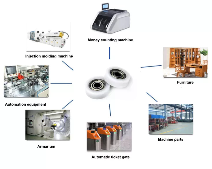
Application Heavy industrial machinery, automation equipment, vehicles, package machines, food processing machines, agricultural machines, electronic machines, etc
Lead Time According to the quantity and drawings’ difficulties of clients
Trade Terms EXW, FOB, CIF, DAP.etc
Drawing Format . pdf / .dwg / .igs / .stp etc.

FAQ

Q1: Are you a trading company or a manufacturer? Location?
A1: We are a factory located in Bao’an, HangZhou, China.

Q2: Is there any MOQ required?
A2: No, there is no MOQ required, even 1 piece we can also process. 

Q3: How to ensure the quality of every process?
A3: The part will be checked when each process is finished, which makes sure there are no defects on the customers’ end.

Q4: How can I get the quotation?
A4: We will offer you the quotation within 12 working hours after receiving your detailed information. In order to quote you faster and more accurate, please provide us with the following information together with your inquiry:
1) CAD or 3D Drawings
2) Tolerance.
3) Material requirement
4) Surface treatment
5) Quantity (per order/per month/annual)
6) Any special demands or requirements, such as packing, labels, delivery, etc.

Q5: How do you make sure my drawings are confidential?
A5: we will keep them well and not release them to others without your permission. NDA can be also signed, if you needed.

Q6: Why choose HangZhou XYX Precision Co., Ltd?
A6:  1. Years of experience, which can offer you tailored solutions to your projects.
        2. Flexibility in lead time.
        3. Assurance in high-quality parts.


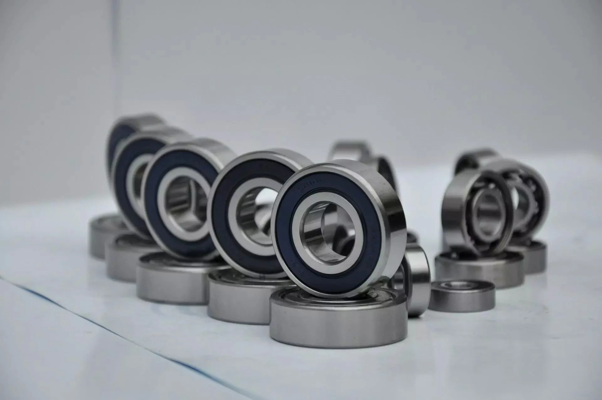
Types of Ball Bearings

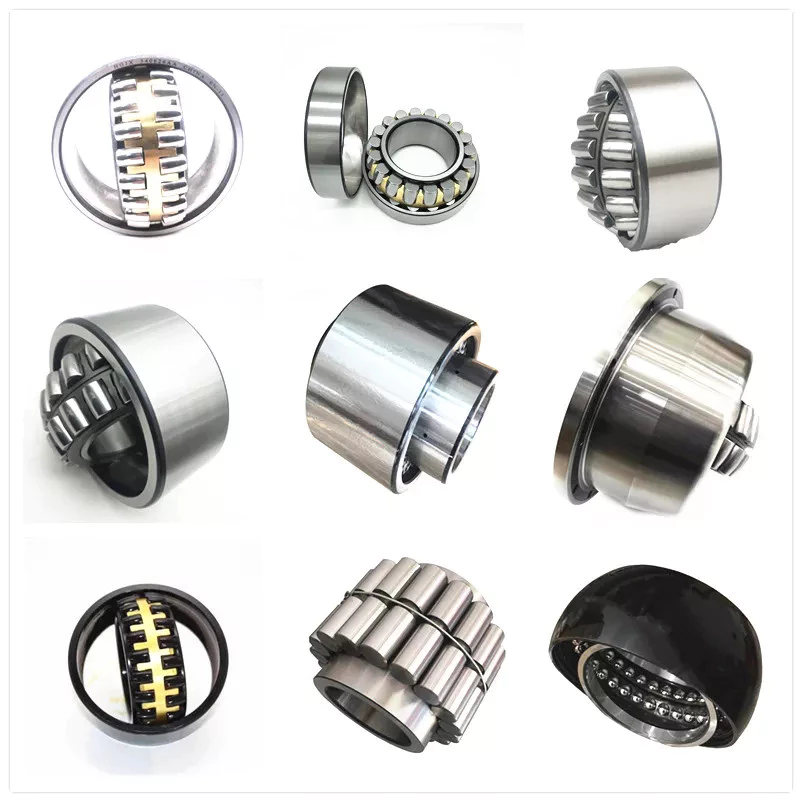
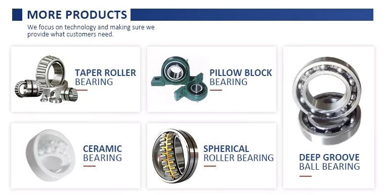
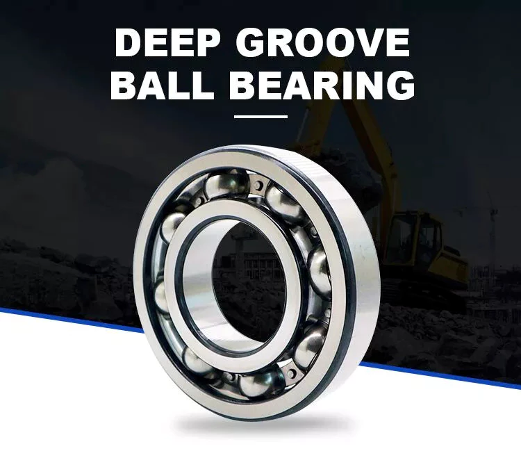
Modern ball bearing configurations have different materials and geometries to meet the demands of different working environments and applications. There are different types of ball bearings: single row deep groove, double-row deep groove, angular contact ball bearing, thrust, and self-aligning. Let us look at the differences between each type and learn why they are important for various purposes. Listed below are some of the most common types of ball bearings.

Miniature bearings

Although miniature ball bearings are a popular choice for small mechanical components, they are not without their challenges. They must be properly lubricated and stored in clean rooms. A strand of hair could ruin a miniature bearing. Fortunately, manufacturers offer lubrication services and a “Clean Room” for customers to store their miniature bearings safely. Read on to learn more about these small bearings and how they can help you.
The size of a miniature ball bearing can vary significantly, but most types of these devices are available in sizes ranging from.040 inch to 1 eighth of an inch. Whether you need a small ball bearing for a miniature car or a tiny instrument, a miniature bearing can save space while still offering high performance. Many of these bearings are shielded to prevent dirt from entering and leakage of lubricant. They can be flanged or unflanged, and some miniature ball bearings have extended inner rings that are designed for easy plate mounting.
Miniature ball bearings are commonly made from stainless steel or chrome steel. Both metals have their advantages. Stainless steel is the most popular material for ball bearings, which allows for a high load capacity while being quiet. Because stainless steel is relatively inexpensive, many small instrument bearings are made entirely of stainless steel. The difference in price is minimal, as the amount of steel is relatively small. Stainless steel miniature bearings are the smallest and lightest of all types of miniature ball bearings.

Self-aligning ball bearings
bearing
In the simplest terms, self-aligning ball bearings are ball bearings with flex shafts. If you’re looking for a ball bearing with a high degree of precision, you’ll want to choose 1 with a flex shaft, which means it can adjust to the proper orientation of the bearing’s flex shaft. Ball bearings with flex shafts are also recommended. But, what are these bearings?
Self-aligning ball bearings are made with 2 rows of balls and a common sphered raceway on the outer ring. As a result, they can accommodate small errors in shaft alignment and mounting. The CZPT brand is especially suitable for high-speed applications requiring greater running accuracy. The self-alignment mechanism is enabled by the fact that the balls are placed in 2 rows on either side of the sphered raceway in the outer ring. These 2 rows of balls also promote reduced friction and wear.
Another type of self-aligning ball bearings is a double-row design. They feature a common sphered raceway on the outer ring, a hollow spherical ring, and a cage that rotates relative to it. A self-aligning ball bearing is used in applications where shaft misalignment is a problem, such as conveying equipment. They are also used in simple woodworking machinery and ventilators.

Ceramic ball bearings

Ceramic ball bearings have several advantages over steel or metal bearings. These include increased acceleration capability, reduced friction, improved wear-resistance, and higher speeds. The United States holds the leading position in the global ceramic ball bearings market thanks to a rebounding motor vehicle production and healthy fixed investment environment. In the United States, there are 3 primary markets for ceramic ball bearings: healthcare, automotive, and aerospace. Here are the main benefits of ceramic ball bearings:
Hybrid ball bearings are also available. Hybrid bearings feature traditional metal rings and silicon nitride (ceramic) balls. Hybrid bearings offer important performance advantages over all-steel bearings, and they are more affordable. However, full ceramic ball bearings have all ceramic parts, and are best suited for machines that require high precision. These types of bearings also resist corrosion and wear.
Compared to steel ball bearings, ceramic balls are lighter than steel. They are also less dense, which means less friction and therefore less heat. Additionally, ceramic balls operate at higher speeds than steel balls, which increases their durability and longevity. But they are still not as strong as steel bearings. And because of their reduced density, they are much cheaper to manufacture. Therefore, they are an excellent choice for many applications. You can expect them to last much longer than steel bearings.

Steel carbon ball bearings

High precision G25 ball bearings are made of the highest grade chrome steel and hot forged from bar stock. Statistical process control and exacting atmospheres help ensure uniform hardness and microstructure. Moreover, these bearings are of the highest quality, with fine surface finish and a tight tolerance. This makes them the most widely used and reliable choice for industrial and automotive applications. However, there are some considerations that should be taken into account before acquiring a steel carbon ball bearing.
Generally, AFBMA grade 200 is the standard hardness specification for this material. AFBMA grade 100 can also be obtained with great difficulty. Despite the high hardness of steel carbon ball bearings, their outer surface is just a thin hardened shell, so a special micro hardness test is needed to evaluate them. In addition to the hardness, steel balls are easily machined and ground. Some manufacturers even offer stainless steel ball bearings and ball sets.
Another factor that makes steel carbon ball bearings so valuable is their precision. They can give precise measurements, which makes them ideal for low and medium-speed applications. Due to their high precision and durability, steel carbon ball bearings can be used in many applications, from conveyor machines to roller skates. However, you should be aware that the material used to produce these bearings is not suitable for applications in which they are exposed to water and gases. Further, they are also noisy and heavy, and must be installed properly in a manufacturing environment.

Stainless steel ball bearings
bearing
Stainless steel ball bearings are made from a high-quality type of stainless steel, 440C, which offers optimal corrosion and abrasion resistance. These bearings are also durable and rust-free, and are suitable for a variety of applications. Among others, stainless steel ball bearings are used in beverage and food processing plants, pharmaceuticals, pulp and paper mills, marine environments, and freezers.
Stainless steel bearings are available in various grades. For example, AISI 440C offers corrosion resistance, while the DD400 is specifically designed for marine applications. Both types of stainless steel are available in different forms, including open, shielded, and sealed. Stainless steel ball bearings can also be custom-made, as BL is known for producing customized bearings. There are also other materials that are available.
AISI type 316 stainless steel balls are ideal for marine applications and food processing. They have excellent resistance to most organic materials and are also used in medical devices and dispenser pumps. They are also strong enough to resist many petroleum products and are widely used in medical equipment and cosmetic applications. In addition, stainless steel balls can be plated to provide an additional layer of protection against chemicals. To understand how they differ, let’s take a look at some common types of stainless steel ball bearings.

Stainless steel

Stainless steel ball bearings can be used in various applications. Besides being corrosion resistant, they also last longer thanks to the Molded-Oil lubrication technology. Stainless steel ball bearings are clean units, which saves time and money in terms of maintenance, replacement, and downtime. But what are the advantages of stainless steel ball bearings? Let us discuss these benefits. Also, we’ll discuss their advantages and disadvantages.
Stainless steel ball bearings offer notable advantages, including corrosion resistance, increased strength, and improved stability under high temperatures. These qualities make them the ideal choice for special circumstances and demanding environments. However, you should be careful when choosing stainless steel bearings. There are several different types of stainless steel. Here’s a brief look at what makes them the best choice. And remember: Stainless steels are also recyclable. In fact, they can be recycled indefinitely.
They’re made from chrome alloy electric furnace steel, which is hardened for optimum service life and strength. They have the highest surface finish and dimensional accuracy. Advanced heat-treating processes increase their strength and anti-cracking abilities. And thanks to their unique materials, they’re corrosion-resistant. As a result, they’re more durable than other types of bearings. And since they’re made with a high-quality steel, you’ll save money in the long run.

Plastic ball bearings
bearing
Plastic ball bearings were developed to meet the specific needs of applications where standard steel bearings would fail. Steel and 440C stainless steel are both susceptible to rusting when exposed to water, making them poor choices for applications involving food processing, swimming pools, and medical equipment. In addition to this, the plastic material is able to dampen vibrations and make the bearing virtually silent. Here’s what makes plastic ball bearings so great for these applications.
Plastic ball bearings are lightweight, corrosion-resistant, and offer a long service life. In addition to their low price, they can be easily cleaned and are incredibly durable. Motion plastics specialist igus has recently expanded its range of xiros polymer grooved ball bearings. These bearings are also FDA-compliant, lubricant-free, electrically insulating, and resistant to both temperature and media.
Plastic bearings are often mounted into other components like wheels, pulleys, and housings. In this way, the inner ring is essentially a profile of the pulley’s profile, and the outer ring is a shaft or fixing clip. The result is seamless integration of the bearing and the surrounding parts, which reduces the overall assembly time and costs. You can also use multiple plastic ball bearings in 1 application for more options.

China manufacturer Custom CNC Millingturning Engine Brass Aluminum Stainless Steel Aluminum Parts     with high qualityChina manufacturer Custom CNC Millingturning Engine Brass Aluminum Stainless Steel Aluminum Parts     with high quality

China Standard CZPT Aw85g Combine Harvester Parts with Hot selling

Product Description

Product Description

Packaging & Shipping

Our Advantages

Company Profile

FAQ


Types of Ball Bearings

If you’re looking to purchase a new ball bearing, there are many different types available. Learn about Single-row designs, Ceramic hybrid bearings, and Self-aligning ball bearings. You can also choose from stainless steel or single-row designs. Then, read about the different types of materials available to you. You’ll have an easier time making a decision. After all, you won’t have to worry about maintaining your new ball bearing, since it will be maintained by your supplier.
bearing

Single-row designs

Ball bearings with a single-row design have a high load-carrying capacity. They are used in applications where high loads must be handled smoothly. A single-row design is a good choice when the material’s properties require high load-carrying capacity but limited axial load capability. Single-row designs use 2 bearings with similar design features, but they have different mounting methods. Single-row designs can be adjusted either against 1 another to accommodate axial loads.
The single-row design is suitable for high-speed applications, but also has some disadvantages. The contact angle a is the angle between the radial plane and contact line. The larger the angle, the higher the axial load carrying capacity of the bearing. Single-row angular contact ball bearings are suitable for higher axial forces. Single-row angular contact ball bearings have a single-row design and support high axial forces in 1 direction. Single-row ball bearings are available in both pressed steel and machined steel cages.
Angular contact ball bearings with a single row feature a cage made of fiber-glass reinforced polyamide 66. These are available in diameters up to 130 mm. Four-point angular contact ball bearings use brass, steel, or brass plate. They have good running properties and a low coefficient of linear expansion. Single-row designs are easy to mount and are widely available. Alternatively, they can be mounted with a universal match design, which allows them to be easily adjusted.
One-row angular contact ball bearings are generally not suitable for angular misalignments because they are unsuitable for compensation of angular misalignments. Misalignments cause internal forces in the bearing which reduce its radial load capacity and life expectancy. This type of bearing is not suitable for adjacent mounting as it increases the chances of misalignment. However, it is a suitable choice for applications where only 1 bearing is required per bearing position.

Ceramic hybrid bearings

While all-ceramic bearings are limited to very specialized applications, Si3N4-based hybrid bearings are finding use in a wide range of high-speed machines. Compared to steel, ceramics are less susceptible to centrifugal forces, which are directly proportional to the mass of the balls. Because Si3N4 replacement balls have a lower density than steel, these bearings reduce the stress placed on the outer race.
The benefits of hybrid bearings are clear: they allow for higher speeds and loads than full-ceramic bearings, and they require no lubrication. Because of their many benefits, many industrial equipment operators are switching to these innovative bearings. CBR is 1 company that specializes in ceramic hybrid bearings and can help you find the best product for your application. If you are thinking about purchasing ceramic bearings for your next machine, here are some things you need to know about them.
A ceramic ball bearing surface has an extremely low coefficient of friction, which is important for applications that require low friction and high speeds. Ceramic balls also have a higher hardness than steel balls, which increases their life. In addition to this, ceramic hybrid bearings have superior thermal properties, generating less heat even when spinning at high speeds. These properties make ceramic hybrid bearings an ideal choice for high-speed machinery, especially electric motors. They are also suitable for applications that operate under water.
A ceramic ball hybrid bearing is much less susceptible to temperature fluctuations and wear. Because they are essentially indestructible, ceramic balls do not generate wear particles from the adhesive wear. They can run at significantly higher speeds than steel balls. Ceramic balls are also more resistant to moisture. For this reason, grease is a recommended lubricant in most ceramic bearing applications. These lubricants offer superior protection against moisture and corrosion. Further, they are available in many types.
bearing

Self-aligning ball bearings

A self-aligning ball bearing is 1 type of self-aligning bearing. These bearings are recommended for use in flex shaft systems. Their self-aligning feature prevents them from misaligning when in use. They can be used in both single and multiple-joint systems. In addition to self-aligning ball bearings, these units also feature flex shafts.
These self-aligning ball bearings come in a variety of configurations, including cylindrical, round, tapered, and straight bore. Their inner ring is tapered to meet specific tolerances. They are suitable for operating temperatures ranging from -30°F to 120°F. Their wide range of applications allows them to be used in general machinery, precision instruments, and low noise motors. In addition, they are available in a variety of outside diameters, widths, and internal clearances.
Self-aligning ball bearings have 2 rows of balls and 1 common sphered raceway in the outer ring. This enables them to automatically compensate for angular misalignment, which may be caused by machining and assembly errors or deflections. Compared to spherical roller bearings, these self-aligning ball bearings generate less friction. They run cooler even at high speeds. Self-aligning ball bearings also offer free engineering support.
Self-aligning ball bearings are designed for difficult shaft alignment. They are double-row, self-retaining units, with cylindrical or tapered bores. These bearings are available in open and sealed designs, and can also be used in applications with misalignment. They are also available with an outer ring that rotates in relation to the inner ring. When it comes to shaft misalignment, self-aligning ball bearings are a great solution.

Stainless steel

Stainless steel is a metal that resists corrosion and is highly durable. Its corrosion-resistant and water-resistance properties make it a good choice for bearings in food and marine applications. Additionally, stainless steel has hygienic benefits. Here are some of the benefits of stainless steel ball bearings. Read on to learn more about these amazing bearings! We’ve included some of the most common uses for stainless steel.
Hardness is important in a ball bearing. Steel uses the Rockwell C scale to measure hardness. A grade 25 steel ball bearing is accurate to 25 millionths of an inch, while a grade 5 ceramic bearing is less than a half-inch round. Although roundness is important, it shouldn’t be overemphasized, as the bearing surfaces may not be as accurate as the grade of the metal. And remember, a higher price tag doesn’t mean a better product.
Stainless steel ball bearings are available in a variety of alloys. The alloys used in manufacturing a stainless steel ball bearing vary in hardness, strength, and ductility. Stainless steel ball bearings have high corrosion-resistance properties. Additionally, they have long lubrication lives. These benefits make them a popular choice for industrial applications. These bearings are easy to maintain, reduce replacement costs, and offer corrosion resistance.
The NTN Sentinel Series is a premium line of stainless steel bearings. The solid lube is NSF H1 registered and prevents grease from leaching into food. It is also corrosion-resistant and doesn’t need to be coated. The seals and slinger create a water-resistant barrier between the steel ball and the lubricant. It also adds safety and security to the bearing.
bearing

Plastic balls

For applications where noise and weight are major concerns, plastic balls are ideal. These non-magnetic balls are ideal for MRI X-ray machines and sensors. They are also easy to lubricate, and are non-magnetic. A polymer ball bearing is the lightest of all 3 types. This makes them a good choice for many industries. Read on to learn more. This article will introduce some of the advantages of plastic balls for ball bearings.
Although ceramic ball bearings are more durable and offer many advantages, they are more expensive than plastic. Fortunately, plastic ball bearings offer a cheaper alternative. These bearings feature all-plastic races and cages. Depending on the application, plastic balls can be used in applications involving chemicals. In these cases, plastic ball bearings are available with a C160 grade, which is safe for use in temperatures below 176 deg F.
Medical devices often require precision specialty balls, which are made of glass, stainless steel, and plastic. These bearings must meet stringent cleanliness requirements. To meet the most stringent requirements, they must undergo ultrasonic cleaning. These bearings are available in plastic raceways, and are also available with glass or stainless steel balls. Polyethylene balls are lightweight and can be used in a variety of applications. They can be ordered in different sizes and tolerances to meet specific requirements.
Plastic balls for ball bearings are often mounted into other parts, such as plastic wheels, pulleys, and housings. They can be seamlessly integrated into other parts of a machine, which reduces assembly time and improves affordability. One important advantage of plastic bearings is that they are rust-resistant. As such, they can be used in harsh environments without causing any damage. If a piece of equipment is exposed to extreme temperatures, polymers are the ideal choice.

China Standard CZPT Aw85g Combine Harvester Parts     with Hot sellingChina Standard CZPT Aw85g Combine Harvester Parts     with Hot selling

China Standard Shenzhen OEM Customized CNC Aluminum Turned Forged Stamping Lathe Machined Tractor ATV/UTV Vehicle Valve Pump Trailer Hydraulic Agricultural Industrial Parts with Best Sales

Product Description

                                                                 A Letter to Our Future Partners
Dear,

Plz wait don’t scroll. No doubt, that partner is you! Thank you for visiting our Xielifeng CNC machining service at MIC now.

Xielifeng Tech is located in HangZhou, China, which focuses on CNC machining, including milling, turning, auto-lathe, die casting. Both metal and plastic material are within our capability. We provide one-stop service, from professional design analysis, to free quote, fast prototype, ISO standard manufacturing, to safe shipping and great after-sales services.

 During these years, we have win lots of trust in the global market, most of them come from North America and Europe. Now you may have steady suppliers, but still hope you can keep us in the archives to get more market news.

More interests, feel free to send us an inquiry via Contact now, or directly to our email, and then our professional sales manager will get back to you ASAP!

Warmly regards.
Peter Tu (Sales Manager)


Service Custom CNC Machining Parts of Most Materials
Quotation According to your drawing(size, material, thickness, processing content, and required technology, etc)
Tolerance & Surface Roughness +/-0.005 – 0.1mm & Ra0.2 – Ra3.2 (Customize available)
Materials Available Aluminum, Copper, Stainless steel, Iron, PE, PVC, ABS, etc.
Surface Treatment Polishing, general/hard/color oxidation, surface chamfering, tempering, etc.
Processing CNC Turning, Milling, Drilling, Auto Lathe, Tapping, Bushing, Surface Treatment, etc.
Payment method Our business face global. and support credit cards, T/T, L/C, Paypal, etc.
Drawing Formats PRO/E, Auto CAD, Solid Works , UG, CAD / CAM / CAE, PDF

FAQ: 

Q1: Where can I get product&price information?
A1: Send us an inquiry in this page or e-mail, we will contact you after upon receipt of your mail.

Q2: How soon can I get samples and how much the fee?
A2: Depending on your specific project, it usually takes 10 to 20 days. the fee depends on the product drawing, and the fee will be returned to your bulk order.

Q3: How to enjoy the OEM services?
A3: Usually, base on your design drawings or original samples, we give some technical proposals and a quotation to you, after your agreement, we produce for you.

Q4: Can you make machining parts based on our samples?
A4: Yes, we can make measurements based on your samples to make drawings for machining parts making.

Q5: Is it possible to know how are my products going on without visiting your company?
A5: We will offer a detailed production schedule and send weekly reports with digital pictures and videos which show the machining progress.

Q6: Will my drawing safe after you get it?
A6: Yes, we can sign the NDA before got your drawing.

Synthesis of Epicyclic Gear Trains for Automotive Automatic Transmissions

In this article, we will discuss the synthesis of epicyclic gear trains for automotive automatic transmissions, their applications, and cost. After you have finished reading, you may want to do some research on the technology yourself. Here are some links to further reading on this topic. They also include an application in hybrid vehicle transmissions. Let’s look at the basic concepts of epicyclic gear trains. They are highly efficient and are a promising alternative to conventional gearing systems.
Gear

Synthesis of epicyclic gear trains for automotive automatic transmissions

The main purpose of automotive automatic transmissions is to maintain engine-drive wheel balance. The kinematic structure of epicyclic gear trains (EGTs) is derived from graph representations of these gear trains. The synthesis process is based on an algorithm that generates admissible epicyclic gear trains with up to 10 links. This algorithm enables designers to design auto gear trains that have higher performance and better engine-drive wheel balance.
In this paper, we present a MATLAB optimization technique for determining the gear ratios of epicyclic transmission mechanisms. We also enumerate the number of teeth for all gears. Then, we estimate the overall velocity ratios of the obtained EGTs. Then, we analyze the feasibility of the proposed epicyclic gear trains for automotive automatic transmissions by comparing their structural characteristics.
A six-link epicyclic gear train is depicted in the following functional diagram. Each link is represented by a double-bicolor graph. The numbers on the graph represent the corresponding links. Each link has multiple joints. This makes it possible for a user to generate different configurations for each EGT. The numbers on the different graphs have different meanings, and the same applies to the double-bicolor figure.
In the next chapter of this article, we discuss the synthesis of epicyclic gear trains for automotive automatic transaxles. SAE International is an international organization of engineers and technical experts with core competencies in aerospace and automotive. Its charitable arm, the SAE Foundation, supports many programs and initiatives. These include the Collegiate Design Series and A World In Motion(r) and the SAE Foundation’s A World in Motion(r) award.
Gear

Applications

The epicyclic gear system is a type of planetary gear train. It can achieve a great speed reduction in a small space. In cars, epicyclic gear trains are often used for the automatic transmission. These gear trains are also useful in hoists and pulley blocks. They have many applications in both mechanical and electrical engineering. They can be used for high-speed transmission and require less space than other types of gear trains.
The advantages of an epicyclic gear train include its compact structure, low weight, and high power density. However, they are not without disadvantages. Gear losses in epicyclic gear trains are a result of friction between gear tooth surfaces, churning of lubricating oil, and the friction between shaft support bearings and sprockets. This loss of power is called latent power, and previous research has demonstrated that this loss is tremendous.
The epicyclic gear train is commonly used for high-speed transmissions, but it also has a small footprint and is suitable for a variety of applications. It is used as differential gears in speed frames, to drive bobbins, and for the Roper positive let-off in looms. In addition, it is easy to fabricate, making it an excellent choice for a variety of industrial settings.
Another example of an epicyclic gear train is the planetary gear train. It consists of 2 gears with a ring in the middle and the sun gear in the outer ring. Each gear is mounted so that its center rotates around the ring of the other gear. The planet gear and sun gear are designed so that their pitch circles do not slip and are in sync. The planet gear has a point on the pitch circle that traces the epicycloid curve.
This gear system also offers a lower MTTR than other types of planetary gears. The main disadvantage of these gear sets is the large number of bearings they need to run. Moreover, planetary gears are more maintenance-intensive than parallel shaft gears. This makes them more difficult to monitor and repair. The MTTR is also lower compared to parallel shaft gears. They can also be a little off on their axis, causing them to misalign or lose their efficiency.
Another example of an epicyclic gear train is the differential gear box of an automobile. These gears are used in wrist watches, lathe machines, and automotives to transmit power. In addition, they are used in many other applications, including in aircrafts. They are quiet and durable, making them an excellent choice for many applications. They are used in transmission, textile machines, and even aerospace. A pitch point is the path between 2 teeth in a gear set. The axial pitch of 1 gear can be increased by increasing its base circle.
An epicyclic gear is also known as an involute gear. The number of teeth in each gear determines its rate of rotation. A 24-tooth sun gear produces an N-tooth planet gear with a ratio of 3/2. A 24-tooth sun gear equals a -3/2 planet gear ratio. Consequently, the epicyclic gear system provides high torque for driving wheels. However, this gear train is not widely used in vehicles.
Gear

Cost

The cost of epicyclic gearing is lower when they are tooled rather than manufactured on a normal N/C milling machine. The epicyclic carriers should be manufactured in a casting and tooled using a single-purpose machine that has multiple cutters to cut the material simultaneously. This approach is widely used for industrial applications and is particularly useful in the automotive sector. The benefits of a well-made epicyclic gear transmission are numerous.
An example of this is the planetary arrangement where the planets orbit the sun while rotating on its shaft. The resulting speed of each gear depends on the number of teeth and the speed of the carrier. Epicyclic gears can be tricky to calculate relative speeds, as they must figure out the relative speed of the sun and the planet. The fixed sun is not at zero RPM at mesh, so the relative speed must be calculated.
In order to determine the mesh power transmission, epicyclic gears must be designed to be able to “float.” If the tangential load is too low, there will be less load sharing. An epicyclic gear must be able to allow “float.” It should also allow for some tangential load and pitch-line velocities. The higher these factors, the more efficient the gear set will be.
An epicyclic gear train consists of 2 or more spur gears placed circumferentially. These gears are arranged so that the planet gear rolls inside the pitch circle of the fixed outer gear ring. This curve is called a hypocycloid. An epicyclic gear train with a planet engaging a sun gear is called a planetary gear train. The sun gear is fixed, while the planet gear is driven.
An epicyclic gear train contains several meshes. Each gear has a different number of meshes, which translates into RPM. The epicyclic gear can increase the load application frequency by translating input torque into the meshes. The epicyclic gear train consists of 3 gears, the sun, planet, and ring. The sun gear is the center gear, while the planets orbit the sun. The ring gear has several teeth, which increases the gear speed.
Another type of epicyclic gear is the planetary gearbox. This gear box has multiple toothed wheels rotating around a central shaft. Its low-profile design makes it a popular choice for space-constrained applications. This gearbox type is used in automatic transmissions. In addition, it is used for many industrial uses involving electric gear motors. The type of gearbox you use will depend on the speed and torque of the input and output shafts.

China Standard Shenzhen OEM Customized CNC Aluminum Turned Forged Stamping Lathe Machined Tractor ATV/UTV Vehicle Valve Pump Trailer Hydraulic Agricultural Industrial Parts     with Best SalesChina Standard Shenzhen OEM Customized CNC Aluminum Turned Forged Stamping Lathe Machined Tractor ATV/UTV Vehicle Valve Pump Trailer Hydraulic Agricultural Industrial Parts     with Best Sales

China Standard CZPT DC60 DC70 Combine Harvester Hst Pump Spare Parts with Best Sales

Product Description

Product Description

Packaging & Shipping

Our Advantages

Company Profile

FAQ


Spiral Gears for Right-Angle Right-Hand Drives

Spiral gears are used in mechanical systems to transmit torque. The bevel gear is a particular type of spiral gear. It is made up of 2 gears that mesh with 1 another. Both gears are connected by a bearing. The 2 gears must be in mesh alignment so that the negative thrust will push them together. If axial play occurs in the bearing, the mesh will have no backlash. Moreover, the design of the spiral gear is based on geometrical tooth forms.
Gear

Equations for spiral gear

The theory of divergence requires that the pitch cone radii of the pinion and gear be skewed in different directions. This is done by increasing the slope of the convex surface of the gear’s tooth and decreasing the slope of the concave surface of the pinion’s tooth. The pinion is a ring-shaped wheel with a central bore and a plurality of transverse axes that are offset from the axis of the spiral teeth.
Spiral bevel gears have a helical tooth flank. The spiral is consistent with the cutter curve. The spiral angle b is equal to the pitch cone’s genatrix element. The mean spiral angle bm is the angle between the genatrix element and the tooth flank. The equations in Table 2 are specific for the Spread Blade and Single Side gears from Gleason.
The tooth flank equation of a logarithmic spiral bevel gear is derived using the formation mechanism of the tooth flanks. The tangential contact force and the normal pressure angle of the logarithmic spiral bevel gear were found to be about 20 degrees and 35 degrees respectively. These 2 types of motion equations were used to solve the problems that arise in determining the transmission stationary. While the theory of logarithmic spiral bevel gear meshing is still in its infancy, it does provide a good starting point for understanding how it works.
This geometry has many different solutions. However, the main 2 are defined by the root angle of the gear and pinion and the diameter of the spiral gear. The latter is a difficult 1 to constrain. A 3D sketch of a bevel gear tooth is used as a reference. The radii of the tooth space profile are defined by end point constraints placed on the bottom corners of the tooth space. Then, the radii of the gear tooth are determined by the angle.
The cone distance Am of a spiral gear is also known as the tooth geometry. The cone distance should correlate with the various sections of the cutter path. The cone distance range Am must be able to correlate with the pressure angle of the flanks. The base radii of a bevel gear need not be defined, but this geometry should be considered if the bevel gear does not have a hypoid offset. When developing the tooth geometry of a spiral bevel gear, the first step is to convert the terminology to pinion instead of gear.
The normal system is more convenient for manufacturing helical gears. In addition, the helical gears must be the same helix angle. The opposite hand helical gears must mesh with each other. Likewise, the profile-shifted screw gears need more complex meshing. This gear pair can be manufactured in a similar way to a spur gear. Further, the calculations for the meshing of helical gears are presented in Table 7-1.
Gear

Design of spiral bevel gears

A proposed design of spiral bevel gears utilizes a function-to-form mapping method to determine the tooth surface geometry. This solid model is then tested with a surface deviation method to determine whether it is accurate. Compared to other right-angle gear types, spiral bevel gears are more efficient and compact. CZPT Gear Company gears comply with AGMA standards. A higher quality spiral bevel gear set achieves 99% efficiency.
A geometric meshing pair based on geometric elements is proposed and analyzed for spiral bevel gears. This approach can provide high contact strength and is insensitive to shaft angle misalignment. Geometric elements of spiral bevel gears are modeled and discussed. Contact patterns are investigated, as well as the effect of misalignment on the load capacity. In addition, a prototype of the design is fabricated and rolling tests are conducted to verify its accuracy.
The 3 basic elements of a spiral bevel gear are the pinion-gear pair, the input and output shafts, and the auxiliary flank. The input and output shafts are in torsion, the pinion-gear pair is in torsional rigidity, and the system elasticity is small. These factors make spiral bevel gears ideal for meshing impact. To improve meshing impact, a mathematical model is developed using the tool parameters and initial machine settings.
In recent years, several advances in manufacturing technology have been made to produce high-performance spiral bevel gears. Researchers such as Ding et al. optimized the machine settings and cutter blade profiles to eliminate tooth edge contact, and the result was an accurate and large spiral bevel gear. In fact, this process is still used today for the manufacturing of spiral bevel gears. If you are interested in this technology, you should read on!
The design of spiral bevel gears is complex and intricate, requiring the skills of expert machinists. Spiral bevel gears are the state of the art for transferring power from 1 system to another. Although spiral bevel gears were once difficult to manufacture, they are now common and widely used in many applications. In fact, spiral bevel gears are the gold standard for right-angle power transfer.While conventional bevel gear machinery can be used to manufacture spiral bevel gears, it is very complex to produce double bevel gears. The double spiral bevel gearset is not machinable with traditional bevel gear machinery. Consequently, novel manufacturing methods have been developed. An additive manufacturing method was used to create a prototype for a double spiral bevel gearset, and the manufacture of a multi-axis CNC machine center will follow.
Spiral bevel gears are critical components of helicopters and aerospace power plants. Their durability, endurance, and meshing performance are crucial for safety. Many researchers have turned to spiral bevel gears to address these issues. One challenge is to reduce noise, improve the transmission efficiency, and increase their endurance. For this reason, spiral bevel gears can be smaller in diameter than straight bevel gears. If you are interested in spiral bevel gears, check out this article.
Gear

Limitations to geometrically obtained tooth forms

The geometrically obtained tooth forms of a spiral gear can be calculated from a nonlinear programming problem. The tooth approach Z is the linear displacement error along the contact normal. It can be calculated using the formula given in Eq. (23) with a few additional parameters. However, the result is not accurate for small loads because the signal-to-noise ratio of the strain signal is small.
Geometrically obtained tooth forms can lead to line and point contact tooth forms. However, they have their limits when the tooth bodies invade the geometrically obtained tooth form. This is called interference of tooth profiles. While this limit can be overcome by several other methods, the geometrically obtained tooth forms are limited by the mesh and strength of the teeth. They can only be used when the meshing of the gear is adequate and the relative motion is sufficient.
During the tooth profile measurement, the relative position between the gear and the LTS will constantly change. The sensor mounting surface should be parallel to the rotational axis. The actual orientation of the sensor may differ from this ideal. This may be due to geometrical tolerances of the gear shaft support and the platform. However, this effect is minimal and is not a serious problem. So, it is possible to obtain the geometrically obtained tooth forms of spiral gear without undergoing expensive experimental procedures.
The measurement process of geometrically obtained tooth forms of a spiral gear is based on an ideal involute profile generated from the optical measurements of 1 end of the gear. This profile is assumed to be almost perfect based on the general orientation of the LTS and the rotation axis. There are small deviations in the pitch and yaw angles. Lower and upper bounds are determined as – 10 and -10 degrees respectively.
The tooth forms of a spiral gear are derived from replacement spur toothing. However, the tooth shape of a spiral gear is still subject to various limitations. In addition to the tooth shape, the pitch diameter also affects the angular backlash. The values of these 2 parameters vary for each gear in a mesh. They are related by the transmission ratio. Once this is understood, it is possible to create a gear with a corresponding tooth shape.
As the length and transverse base pitch of a spiral gear are the same, the helix angle of each profile is equal. This is crucial for engagement. An imperfect base pitch results in an uneven load sharing between the gear teeth, which leads to higher than nominal loads in some teeth. This leads to amplitude modulated vibrations and noise. In addition, the boundary point of the root fillet and involute could be reduced or eliminate contact before the tip diameter.

China Standard CZPT DC60 DC70 Combine Harvester Hst Pump Spare Parts     with Best SalesChina Standard CZPT DC60 DC70 Combine Harvester Hst Pump Spare Parts     with Best Sales

China Professional Spare Parts of CZPT DC60 Combine Harvester with Good quality

Product Description

Product Description

Packaging & Shipping

Our Advantages

Company Profile

FAQ


How to Choose the Right Worm Shaft

You might be curious to know how to choose the right Worm Shaft. In this article, you will learn about worm modules with the same pitch diameter, Double-thread worm gears, and Self-locking worm drive. Once you have chosen the proper Worm Shaft, you will find it easier to use the equipment in your home. There are many advantages to selecting the right Worm Shaft. Read on to learn more.
worm shaft

Concave shape

The concave shape of a worm’s shaft is an important characteristic for the design of a worm gearing. Worm gearings can be found in a wide range of shapes, and the basic profile parameters are available in professional and firm literature. These parameters are used in geometry calculations, and a selection of the right worm gearing for a particular application can be based on these requirements.
The thread profile of a worm is defined by the tangent to the axis of its main cylinder. The teeth are shaped in a straight line with a slightly concave shape along the sides. It resembles a helical gear, and the profile of the worm itself is straight. This type of gearing is often used when the number of teeth is greater than a certain limit.
The geometry of a worm gear depends on the type and manufacturer. In the earliest days, worms were made similar to simple screw threads, and could be chased on a lathe. During this time, the worm was often made with straight-sided tools to produce threads in the acme plane. Later, grinding techniques improved the thread finish and reduced distortions resulting from hardening.
When a worm gearing has multiple teeth, the pitch angle is a key parameter. A greater pitch angle increases efficiency. If you want to increase the pitch angle without increasing the number of teeth, you can replace a worm pair with a different number of thread starts. The helix angle must increase while the center distance remains constant. A higher pitch angle, however, is almost never used for power transmissions.
The minimum number of gear teeth depends on the angle of pressure at zero gearing correction. The diameter of the worm is d1, and is based on a known module value, mx or mn. Generally, larger values of m are assigned to larger modules. And a smaller number of teeth is called a low pitch angle. In case of a low pitch angle, spiral gearing is used. The pitch angle of the worm gear is smaller than 10 degrees.
worm shaft

Multiple-thread worms

Multi-thread worms can be divided into sets of one, two, or 4 threads. The ratio is determined by the number of threads on each set and the number of teeth on the apparatus. The most common worm thread counts are 1,2,4, and 6. To find out how many threads you have, count the start and end of each thread and divide by two. Using this method, you will get the correct thread count every time.
The tangent plane of a worm’s pitch profile changes as the worm moves lengthwise along the thread. The lead angle is greatest at the throat, and decreases on both sides. The curvature radius r” varies proportionally with the worm’s radius, or pitch angle at the considered point. Hence, the worm leads angle, r, is increased with decreased inclination and decreases with increasing inclination.
Multi-thread worms are characterized by a constant leverage between the gear surface and the worm threads. The ratio of worm-tooth surfaces to the worm’s length varies, which enables the wormgear to be adjusted in the same direction. To optimize the gear contact between the worm and gear, the tangent relationship between the 2 surfaces is optimal.
The efficiency of worm gear drives is largely dependent on the helix angle of the worm. Multiple thread worms can improve the efficiency of the worm gear drive by as much as 25 to 50% compared to single-thread worms. Worm gears are made of bronze, which reduces friction and heat on the worm’s teeth. A specialized machine can cut the worm gears for maximum efficiency.

Double-thread worm gears

In many different applications, worm gears are used to drive a worm wheel. These gears are unique in that the worm cannot be reversed by the power applied to the worm wheel. Because of their self-locking properties, they can be used to prevent reversing motion, although this is not a dependable function. Applications for worm gears include hoisting equipment, elevators, chain blocks, fishing reels, and automotive power steering. Because of their compact size, these gears are often used in applications with limited space.
Worm sets typically exhibit more wear than other types of gears, and this means that they require more limited contact patterns in new parts. Worm wheel teeth are concave, making it difficult to measure tooth thickness with pins, balls, and gear tooth calipers. To measure tooth thickness, however, you can measure backlash, a measurement of the spacing between teeth in a gear. Backlash can vary from 1 worm gear to another, so it is important to check the backlash at several points. If the backlash is different in 2 places, this indicates that the teeth may have different spacing.
Single-thread worm gears provide high speed reduction but lower efficiency. A multi-thread worm gear can provide high efficiency and high speed, but this comes with a trade-off in terms of horsepower. However, there are many other applications for worm gears. In addition to heavy-duty applications, they are often used in light-duty gearboxes for a variety of functions. When used in conjunction with double-thread worms, they allow for a substantial speed reduction in 1 step.
Stainless-steel worm gears can be used in damp environments. The worm gear is not susceptible to rust and is ideal for wet and damp environments. The worm wheel’s smooth surfaces make cleaning them easy. However, they do require lubricants. The most common lubricant for worm gears is mineral oil. This lubricant is designed to protect the worm drive.
worm shaft

Self-locking worm drive

A self-locking worm drive prevents the platform from moving backward when the motor stops. A dynamic self-locking worm drive is also possible but does not include a holding brake. This type of self-locking worm drive is not susceptible to vibrations, but may rattle if released. In addition, it may require an additional brake to keep the platform from moving. A positive brake may be necessary for safety.
A self-locking worm drive does not allow for the interchangeability of the driven and driving gears. This is unlike spur gear trains that allow both to interchange positions. In a self-locking worm drive, the driving gear is always engaged and the driven gear remains stationary. The drive mechanism locks automatically when the worm is operated in the wrong manner. Several sources of information on self-locking worm gears include the Machinery’s Handbook.
A self-locking worm drive is not difficult to build and has a great mechanical advantage. In fact, the output of a self-locking worm drive cannot be backdriven by the input shaft. DIYers can build a self-locking worm drive by modifying threaded rods and off-the-shelf gears. However, it is easier to make a ratchet and pawl mechanism, and is significantly less expensive. However, it is important to understand that you can only drive 1 worm at a time.
Another advantage of a self-locking worm drive is the fact that it is not possible to interchange the input and output shafts. This is a major benefit of using such a mechanism, as you can achieve high gear reduction without increasing the size of the gear box. If you’re thinking about buying a self-locking worm gear for a specific application, consider the following tips to make the right choice.
An enveloping worm gear set is best for applications requiring high accuracy and efficiency, and minimum backlash. Its teeth are shaped differently, and the worm’s threads are modified to increase surface contact. They are more expensive to manufacture than their single-start counterparts, but this type is best for applications where accuracy is crucial. The worm drive is also a great option for heavy trucks because of their large size and high-torque capacity.

China Professional Spare Parts of CZPT DC60 Combine Harvester     with Good qualityChina Professional Spare Parts of CZPT DC60 Combine Harvester     with Good quality

China Good quality Bicycle Spare Parts of Bell, Horn, Flower Sharp with Great quality

Product Description

Product Description

product name  bicycle bell /horn
material  steel + plastic
color   
character lovely small 
   

small + nice working 

Packaging & Shipping

1pcs/polybag  500 pcs/CTN   separated by cardboard 
delievery time : 30 days after deposit

Company Profile

ZheJiang HongChi bicycle Co. Ltd located in the biggest bicycle accessory base. We get a wonderful geography, convenient traffic which near to the Jingzhu and Xihu (West Lake) Dis.g high speed way. And our company is closed to the famous China Bicycle Accessory Town.
We are professional manufacturer in producing chain wheel&crank, saddle, inner tube, tyre, pedal, front axle, rear axle, MTB bicycle, BMX bicycle, child toys, etc. branded “HongChi”. Meanwhile, we have the autonomy in operation of the import and export business. Our company has a dozen of great profession product machines. And our productions get a well sale to the bicycle factory and accessories manufactures production all over the country, which based on good quality, cheap price, and perfect after-sales service. So our export sales have been growing year by year. Our productions are spreading over 40 countries and regions including Southeast Asia, East Europe, Africa, and South America.
Hard work and CZPT pursuit is our spirit. Quality first and customer first is our principle. Everyone in HongChi Company is sincerely inviting the colleague all over the world to have cooperation and a better future

How to use the pulley system

Using a pulley system is a great way to move things around your home, but how do you use a pulley system? Let’s look at the basic equations that describe a pulley system, the types of pulleys, and some safety considerations when using pulleys. Here are some examples. Don’t worry, you’ll find all the information you need in 1 place!
pulley

Basic equations of pulley systems

The pulley system consists of pulleys and chords. When the weight of the load is pulled through the rope, it slides through the groove and ends up on the other side. When the weight moves, the applied force must travel nx distance. The distance is in meters. If there are 4 pulleys, the distance the rope will travel will be 2×24. If there are n pulleys, the distance traveled by the weight will be 2n – 1.
The mechanical advantage of the pulley system increases with distance. The greater the distance over which the force is applied, the greater the leverage of the system. For example, if a set of pulleys is used to lift the load, 1 should be attached to the load and the other to the stand. The load itself does not move. Therefore, the distance between the blocks must be shortened, and the length of the line circulating between the pulleys must be shortened.
Another way to think about the acceleration of a pulley system is to think of ropes and ropes as massless and frictionless. Assuming the rope and pulley are massless, they should have the same magnitude and direction of motion. However, in this case the quality of the string is a variable that is not overdone. Therefore, the tension vector on the block is labeled with the same variable name as the pulley.
The calculation of the pulley system is relatively simple. Five mechanical advantages of the pulley system can be found. This is because the number of ropes supporting the load is equal to the force exerted on the ropes. When the ropes all move in the same direction, they have 2 mechanical advantages. Alternatively, you can use a combination of movable and fixed pulleys to reduce the force.
When calculating forces in a pulley system, you can use Newton’s laws of motion. Newton’s second law deals with acceleration and force. The fourth law tells us that tension and gravity are in equilibrium. This is useful if you need to lift heavy objects. The laws of motion help with calculations and can help you better understand pulley systems.
pulley

Types of pulleys

Different types of pulleys are commonly used for various purposes, including lifting. Some pulleys are flexible, which means they can move freely around a central axis and can change the direction of force. Some are fixed, such as hinges, and are usually used for heavier loads. Others are movable, such as coiled ropes. Whatever the purpose, pulleys are very useful in raising and lowering objects.
Pulleys are common in many different applications, from elevators and cargo lift systems to lights and curtains. They are also used in sewing machine motors and sliding doors. Garage and patio doors are often equipped with pulleys. Rock climbers use a pulley system to climb rocks safely. These pulley systems have different types of pinions that allow them to balance weight and force direction.
The most common type of pulley is the pulley pulley system. The pulley system utilizes mechanical advantages to lift weight. Archimedes is thought to have discovered the pulley around 250 BC. in ancient Sicily. Mesopotamians also used pulleys, they used ropes to lift water and windmills. Pulley systems can even be found at Stonehenge.
Another type of pulley is called a compound pulley. It consists of a set of parallel pulleys that increase the force required to move large objects. This type is most commonly used in rock climbing and sailing, while composite pulleys can also be found in theater curtains. If you’re wondering the difference between these 2 types of pulleys, here’s a quick overview:

Mechanical Advantages of Pulley Systems

Pulley systems offer significant mechanical advantages. The ability of the system to reduce the effort required to lift weights increases with the number of rope loops. This advantage is proportional to the number of loops in the system. If the rope had only 1 loop, then a single weight would require the same amount of force to pull. But by adding extra cycles, the force required will be reduced.
The pulley system has the advantage of changing the direction of the force. This makes it easier to move heavy objects. They come in both fixed and mobile. Pulleys are used in many engineering applications because they can be combined with other mechanisms. If you want to know what a pulley can do, read on! Here are some examples. Therefore, you will understand how they are used in engineering.
Single-acting pulleys do not change direction, but compound pulleys do. Their mechanical advantage is six. The compound pulley system consists of a movable pulley and a fixed pulley. The mechanical advantage of the pulley system increases as the number of movable wheels decreases. So if you have 2 wheels, you need twice as much force to lift the same weight because you need a movable pulley.
The mechanical advantage of a pulley system can be maximized by adding more pulleys or rope lengths. For example, if you have a single pulley system, the mechanical advantage is 1 of the smallest. By using 2 or 3 pulleys, up to 5 times the mechanical advantage can be achieved. You can also gain up to 10 times the mechanical advantage by using multiple pulley systems.
The use of a single movable pulley system also adds to the mechanical advantage of the pulley system. In this case, you don’t have to change the direction of the force to lift the weight. In contrast, a movable pulley system requires you to move the rope farther to generate the same force. Using a compound pulley system allows you to lift heavy loads with ease.
pulley

Safety Issues When Using Pulley Systems

Pulleys have an incredibly unique structure, consisting of a disc with a groove in the middle and a shaft running through it. A rope or cord is attached to 1 end of a pulley that turns when force is applied. The other end of the rope is attached to the load. This mechanical advantage means that it is much easier to pull an object using the pulley system than to lift the same object by hand.
Although pulley systems are a common part of many manufacturing processes, some employers do not train their workers to use them properly or install protection to prevent injury. It is important to wear proper PPE and follow standard laboratory safety practices during pulley system activities. Make sure any support structures are strong enough to handle the weight and weight of the rope or rope. If you do fall, be sure to contact your employer immediately.

China Good quality Bicycle Spare Parts of Bell, Horn, Flower Sharp     with Great qualityChina Good quality Bicycle Spare Parts of Bell, Horn, Flower Sharp     with Great quality

China Good quality CZPT DC70 Combine Harvester Parts 5t072-5141-0 Knife Guard near me supplier

Product Description

CZPT DC70 Combine Harvester parts 5T072-5141-0 Knife guard 

company information:

SHUNYU mainly supply Farm tractors, Harvesters and spare parts.


Including KUBOTA, YANMAR, WORLD combine harvesters spare parts.

We could not put all of our products on website

If you have any needs, welcome to contact us and we disucss accordingly.


Understanding the Different Types of Bearings

When you are looking for a bearing, you have many options to choose from. This article will explain the various types, functions, and working principles of different types of bearings. Once you understand the basic components, you can make an informed decision about which 1 to buy. Here’s an overview of some of the most common types. Learn more about each type below! Read on to learn about the differences between these different types of bearings! Posted in Articles

Functions

bearing
Bearings serve as an integral part of a mechanical device. These devices help transfer torque from 1 part of a structure to another. These mechanisms increase the efficiency of a shaft by increasing its life. However, the functions of bearings depend on the application of the structure. Among other functions, bearings provide support to shafts. Anti-friction bearings come in 2 types: ball and roller bearings. These components have line and point contact, which is the most common type. Archimedes’s principle states that the force is equal to the weight of the fluid that is being displaced. Bearings can transfer lateral loads to a substructure.
A bearing has 2 primary functions. The first is to prevent direct metal-to-metal contact. A bearing prevents friction, heat generation, and wear and tear of components. A bearing also reduces energy consumption. Its other purpose is to guide and support a rotating body. In addition to these functions, bearings can also reduce wear and tear on a machine. As a result, they are among the most widely used machines in the world.
Seals are a major component of a bearing. They prevent foreign materials from entering and lubricating the moving parts. The design of seal lips determines their effectiveness. Fuel economy regulations and CO2 emissions regulations are pushing the demand for low-friction bearings. However, high-performance seals do not always provide high-performance. As a result, current estimations of the friction in bearings depend on trial and error methods.
Another important function of bearings is that they transfer the load of a rotating component to its housing. This load can be axial or radial. Bearings also limit movement to predefined directions. Some types of rolling element bearings have balls or cylinders inside. These bearings are less frictional than sliding ones, thus they allow parts to move freely during rotation. These parts can then be used for various applications. So, bearings are an integral part of machines.

Types

The most common type of bearing is a plain bearing. It uses surfaces in rubbing contact to transmit movement from 1 part to another. These bearings may be discrete or may consist of a hole in a metal sleeve or a planar surface bearing another part. Some plain bearings are flanged, while others are made of a sleeve with a flange at 1 end. These bearings often give acceptable accuracy and life, but they are expensive and cannot be used in large scale applications.
Radial bearings are used when there is a need for high-speed or corrosive parts. This type of bearing also serves as a support in an intermediate situation. Its 2 components are called the base and the cover. The base and cover are connected and are arranged parallel to the main axis. This type of bearing is used in steady-state and axial motion applications. The radial bearings are also used when the shafts are long.
Angular contact bearings are another type of bearing. These are easy to install and require minimal maintenance. Their races are displaced along the axis. They are also better at handling axial loads and transferring them to the housing. These types of bearings are commonly used in pumps, automobiles, and high-speed applications. If you are looking for an affordable, reliable bearing, look no further than the angular contact bearing.
Another type of bearing is a self-lubricating bushing. These are lightweight and wear-resistant. Unlike the other types of bearing, they do not require any lubrication or maintenance. In fact, some are completely maintenance-free. But if you’re worried about maintenance, this type of bearing may be a good choice. There are many benefits of using self-lubricating bushings. It is also a good option for applications where your machine is exposed to extreme temperatures.

Working principle

bearing
A bearing has 2 primary functions: support and load transfer. In engineering applications, the bearing tends to push the load in the direction of the shaft. A radial load pushes the bearing downward and a thrust load pushes it sideways. Both types of load transfer are important in a variety of applications. The working principle of each type is described below. Listed below are the main uses for each type of bearing.
A plain bearing uses a PTFE liner on the interface of 2 moving parts. The PTFE liner acts as a lubricant and may be filtered to alter its friction. The journal bearing uses the motion of the journal to force fluid into the gap between 2 moving parts. This results in a small amount of play in the bearing. This play is acceptable for most applications. A ball bearing may have a maximum play of 2 mm for a ten-millimeter shaft.
The primary function of a bearing is to assist in rotation and to reduce mechanical friction between the 2 objects. A bearing may be installed as a separate device or as an integral part of a machine. For more complex applications, bearings are very precise components requiring the highest standards of technology. For this reason, it is important to understand the working principle of bearings. The next time you need to lift or slide a heavy object, consider a bearing.
Ball bearings are a common type of ball bearing and can be found in industrial machinery and automobiles. Their unique structure helps them support less weight. This is because they are comprised of 2 rings – an inner race and an outer race. The balls themselves have a small area of contact and transfer axial loads in 1 direction. A cage surrounds the balls and prevents them from colliding. This makes ball bearings a popular choice for many applications.

Sealing system

A bearing’s seals are vital for the operation of rolling and rotating components. These systems enable rotation and linear movement while limiting friction and dispersing stress. Without the proper seals, these components could face catastrophic failure. In addition to protecting the bearing from external forces, seals help retain lubricant inside the system and prevent harmful particles from entering the gap. A seal’s lubrication helps prevent the onset of mechanical damage and prolongs the life of the bearing.
A bearing seal is made up of 2 parts: the inner sealing element and the outer sealing element. A passageway runs through the bearing assembly to the outer seal element. A hydraulic press or pneumatic jack is recommended for installing the seal. These tools are effective in reducing deformation and improving seal installation quality. When fitting the seal, ensure that the tool does not hit the seal directly. A proper adopter will distribute the load uniformly across the seal.
The seal’s efficiency depends on its gap. A four-inch shaft seal can flow 0.5 standard cubic feet per minute. A seal’s efficiency is highly dependent on the gap size. The gap size is a cube of the flow through the system. A smaller gap size allows high flow and pressure but less leakage. If both surfaces of the seal have similar pressures and flow rates, the seal is efficient. However, a small gap reduces the pressures and reduces wear.
Mechanical seals have numerous advantages, including their ability to protect against contaminants and splashing liquids. Labyrinth seals are the first line of defense against leaks. They operate without friction. Their high level of sealing efficiency helps ensure that the bearing remains operational for long. This type of seal is made from metal plates and is designed for a wide temperature range and misalignment. Its advantages include being easy to install and offering 100% sealing efficiency.

Maintenance

bearing
Bearing maintenance is critical to ensuring that your bearings keep operating at their peak performance. Proper maintenance will improve bearing life, reduce downtime and increase productivity while reducing costs. Here is an 8-point checklist to optimize your bearings and make them last longer. To optimize their performance, you should follow these steps regularly. In case a bearing does not last long, you should replace it as soon as possible. Listed below are some tips to ensure proper maintenance.
The first step is to determine how often your bearings require lubrication. Some manufacturers recommend that you lubricate them weekly, but this can do more harm than good. Instead, use ultrasound to measure the level of friction and trend its levels. This way, you will know exactly when to grease your bearings. It’s also important to check how often they should be inspected and calibrated. A professional can provide guidance on proper maintenance.
Next, inspect your bearings for cracks and scratches. You should never install a bearing that has been dropped or scratched. Even a small crack will affect the performance of the bearing and could lead to its premature failure. A proper alignment is essential for the bearing to function properly. Make sure you have the correct tools to perform this task. These tools can help you reduce manual work and promote safe bearing maintenance. You should also ensure that the shaft and housing are clean and undamaged.
Proper maintenance can prolong bearing service life. Proper lubrication, mounting, inspection, basic condition monitoring, and dismounting can extend their life. Proper maintenance extends their lifespan and improves plant productivity. While bearings are essential for machinery, you should make sure you follow the proper safety procedures every time you work with them. These tips will also help prevent accidents and maintain your machine’s efficiency. Once you’ve followed these guidelines, you can safely inspect your bearings and ensure that they’re operating at their optimum capacity.

China Good quality CZPT DC70 Combine Harvester Parts 5t072-5141-0 Knife Guard     near me supplier China Good quality CZPT DC70 Combine Harvester Parts 5t072-5141-0 Knife Guard     near me supplier

China Best Sales Farm Disc Plough Forging Ploug Hub Mf Tube Disc Plough Casting Hub Plough Parts near me supplier

Product Description

Advantages:
Weight: 40kg.
Hole distance: 251mm or 228mm.
Forging plough hub.

We also product Bladan type Disc plough hub ,, wheel cover ,shafts, legs,Forks, Disc Harrow Bearing Assemble  etc. 

Main Features for YCHS MACHINERY

1) Many years of manufacturing expenrience in the field of general machineries. 
2) Professional engineers and test equipments to ensure the quality of each machine.
3) Factory direct selling at competitive prices. 
4) Good parts assembled, strictly quality control system.
5) Compact structure, beautiful appearance,small volume, light weight, fuel consumption is low, the power is great
6) Start convenient easy, low noise,little vibration,smooth operation,reliable performance.
7) OEM welcome, small order acceptable, ample supply and prompt delivery.

Competitive Advantages For YCHS MACHINERY

1) Most kinds of models, advanced technology, long performance life.
2) We are manufacturer and we have our own export right.
3) High quality, competitive price & good after-sales service.
4) Long exporting history to many countries, positive customer feedback from abroad.
5) We can supply sample, and also all the spare parts. 
6) As your design for the package and brands
 
1) YCHS MACHIERY is a  manufacturer, have  own factories.
2) The biggest advantages: Top quality, Competitive price & Good after-sales service
 
Top quality, Competitive price, Good after-sales service” is our three big advantage.
Welcome to contact us at any moment, sincerely hope can have  cooperation with you !

Agricultural disc plow  YTO tractor mounted tubular disk plough.

FAQ
 

Q1: Are you a factory or trading company?
We are a factory with self-supported import and export right. 
Q2: How can I trust on your company?
We are a fully registered manufacture and exporting company by China Export Registration Authorities. Moreover, our products have been exporting to a number of countries including Switzerland, Russia, Spain, Netherlands, Australia, Peru, Thailand, Pakistan, Indonesia, Tanzania, Nigeria, South Africa, Sudan, Congo etc. The good faith, punctual, strict quality control and reasonable price, throughout is the pledge we to each customer.
Q3: Where is your factory located? How can I visit there?
Our factory is located in HangZhou City, ZheJiang Province, China.  About 1 hour away from HangZhou Airport. All our clients are warmly welcomed to visit us!
Q4: How can I place an order from your website?
It is very easy.Once you find the implement you need on our website and place an inquiry against it, or, get to the inquiry section and leave us a message there with name, country and phone number, we will get in touch with you at the earliest. You can also e-mail us directly or join us on live chat for instantaneous answers.
Q5: How can I make the payment?
Payment is made via Telegraphic Transfer (T/T) through the bank against the proforma invoice.
30% as prepayment and the balance when the goods are ready for shipping.
Irrevocable L/C at sight could be also accepted.
Q6: What’s the Payment terms?
FOB, the price of the implement without sea shipment costs. CIF,  including the unit cost + marine insurance + Shipment charges to your destination port. CFR, including the unit cost + Shipment charges to your destination port.
Q7: At which port do you usually ship the good?
We usually ship goods via HangZhou, ZheJiang , HangZhou, ZheJiang port of China.
Q8. How about the Warranty ?
12 months warranty from the time of the goods arrive at destination.

How to Replace the Drive Shaft

Several different functions in a vehicle are critical to its functioning, but the driveshaft is probably the part that needs to be understood the most. A damaged or damaged driveshaft can damage many other auto parts. This article will explain how this component works and some of the signs that it may need repair. This article is for the average person who wants to fix their car on their own but may not be familiar with mechanical repairs or even driveshaft mechanics. You can click the link below for more information.
air-compressor

Repair damaged driveshafts

If you own a car, you should know that the driveshaft is an integral part of the vehicle’s driveline. They ensure efficient transmission of power from the engine to the wheels and drive. However, if your driveshaft is damaged or cracked, your vehicle will not function properly. To keep your car safe and running at peak efficiency, you should have it repaired as soon as possible. Here are some simple steps to replace the drive shaft.
First, diagnose the cause of the drive shaft damage. If your car is making unusual noises, the driveshaft may be damaged. This is because worn bushings and bearings support the drive shaft. Therefore, the rotation of the drive shaft is affected. The noise will be squeaks, dings or rattles. Once the problem has been diagnosed, it is time to repair the damaged drive shaft.
Professionals can repair your driveshaft at relatively low cost. Costs vary depending on the type of drive shaft and its condition. Axle repairs can range from $300 to $1,000. Labor is usually only around $200. A simple repair can cost between $150 and $1700. You’ll save hundreds of dollars if you’re able to fix the problem yourself. You may need to spend a few more hours educating yourself about the problem before handing it over to a professional for proper diagnosis and repair.
The cost of repairing a damaged driveshaft varies by model and manufacturer. It can cost as much as $2,000 depending on parts and labor. While labor costs can vary, parts and labor are typically around $70. On average, a damaged driveshaft repair costs between $400 and $600. However, these parts can be more expensive than that. If you don’t want to spend money on unnecessarily expensive repairs, you may need to pay a little more.
air-compressor

Learn how drive shafts work

While a car engine may be 1 of the most complex components in your vehicle, the driveshaft has an equally important job. The driveshaft transmits the power of the engine to the wheels, turning the wheels and making the vehicle move. Driveshaft torque refers to the force associated with rotational motion. Drive shafts must be able to withstand extreme conditions or they may break. Driveshafts are not designed to bend, so understanding how they work is critical to the proper functioning of the vehicle.
The drive shaft includes many components. The CV connector is 1 of them. This is the last stop before the wheels spin. CV joints are also known as “doughnut” joints. The CV joint helps balance the load on the driveshaft, the final stop between the engine and the final drive assembly. Finally, the axle is a single rotating shaft that transmits power from the final drive assembly to the wheels.
Different types of drive shafts have different numbers of joints. They transmit torque from the engine to the wheels and must accommodate differences in length and angle. The drive shaft of a front-wheel drive vehicle usually includes a connecting shaft, an inner constant velocity joint and an outer fixed joint. They also have anti-lock system rings and torsional dampers to help them run smoothly. This guide will help you understand the basics of driveshafts and keep your car in good shape.
The CV joint is the heart of the driveshaft, it enables the wheels of the car to move at a constant speed. The connector also helps transmit power efficiently. You can learn more about CV joint driveshafts by looking at the top 3 driveshaft questions
The U-joint on the intermediate shaft may be worn or damaged. Small deviations in these joints can cause slight vibrations and wobble. Over time, these vibrations can wear out drivetrain components, including U-joints and differential seals. Additional wear on the center support bearing is also expected. If your driveshaft is leaking oil, the next step is to check your transmission.
The drive shaft is an important part of the car. They transmit power from the engine to the transmission. They also connect the axles and CV joints. When these components are in good condition, they transmit power to the wheels. If you find them loose or stuck, it can cause the vehicle to bounce. To ensure proper torque transfer, your car needs to stay on the road. While rough roads are normal, bumps and bumps are common.
air-compressor

Common signs of damaged driveshafts

If your vehicle vibrates heavily underneath, you may be dealing with a faulty propshaft. This issue limits your overall control of the vehicle and cannot be ignored. If you hear this noise frequently, the problem may be the cause and should be diagnosed as soon as possible. Here are some common symptoms of a damaged driveshaft. If you experience this noise while driving, you should have your vehicle inspected by a mechanic.
A clanging sound can also be 1 of the signs of a damaged driveshaft. A ding may be a sign of a faulty U-joint or center bearing. This can also be a symptom of worn center bearings. To keep your vehicle safe and functioning properly, it is best to have your driveshaft inspected by a certified mechanic. This can prevent serious damage to your car.
A worn drive shaft can cause difficulty turning, which can be a major safety issue. Fortunately, there are many ways to tell if your driveshaft needs service. The first thing you can do is check the u-joint itself. If it moves too much or too little in any direction, it probably means your driveshaft is faulty. Also, rust on the bearing cap seals may indicate a faulty drive shaft.
The next time your car rattles, it might be time for a mechanic to check it out. Whether your vehicle has a manual or automatic transmission, the driveshaft plays an important role in your vehicle’s performance. When 1 or both driveshafts fail, it can make the vehicle unsafe or impossible to drive. Therefore, you should have your car inspected by a mechanic as soon as possible to prevent further problems.
Your vehicle should also be regularly lubricated with grease and chain to prevent corrosion. This will prevent grease from escaping and causing dirt and grease to build up. Another common sign is a dirty driveshaft. Make sure your phone is free of debris and in good condition. Finally, make sure the driveshaft chain and cover are in place. In most cases, if you notice any of these common symptoms, your vehicle’s driveshaft should be replaced.
Other signs of a damaged driveshaft include uneven wheel rotation, difficulty turning the car, and increased drag when trying to turn. A worn U-joint also inhibits the ability of the steering wheel to turn, making it more difficult to turn. Another sign of a faulty driveshaft is the shuddering noise the car makes when accelerating. Vehicles with damaged driveshafts should be inspected as soon as possible to avoid costly repairs.

China Best Sales Farm Disc Plough Forging Ploug Hub Mf Tube Disc Plough Casting Hub Plough Parts     near me supplier China Best Sales Farm Disc Plough Forging Ploug Hub Mf Tube Disc Plough Casting Hub Plough Parts     near me supplier

China Best Sales Agricultural Tractor Farm Machinery Casting Partsprofessional Agricultural Tractor Spare Part with Good Quality Made by XP Casting wholesaler

Product Description

We are a foundry for casting processed products.
With more than 10 years of experience, our products have been exported to the United States, Germany, Italy, Spain, etc.
Our engineers have more than 10 years experience in quality control and can guarantee the highest quality of castings
A factory that integrates casting, heat treatment, and machining capabilities to achieve lower costs

Process Shell Model Casting,Heat treatment,CNC machining,
Equipment Semi automatic casting line.CNC centers, CNC turning, CNC lathes, line cutting, milling, drilling, grinding
Material ASTM (60-40-18,65-45-12,70-50-05,80-60-03,100-70-03).ect.
Surface Trimming, Deburring,Polishing, Shot blasting, Sand blasting,Tumbling, Powder coating, Anodizing, Chrome, Zinc, Electrophoresis, 
Software Assistance Pro-e/Solid work/UG/Auto CAD
Products Application Auto Parts, Agricultural Machinery Parts, Power Parts, Railway Machinery Parts, Construction Machinery Parts, Elevator Parts.ect.


What is a driveshaft and how much does it cost to replace one?

Your vehicle is made up of many moving parts. Knowing each part is important because a damaged driveshaft can seriously damage other parts of the car. You may not know how important your driveshaft is, but it’s important to know if you want to fix your car. In this article, we’ll discuss what a driveshaft is, what its symptoms are, and how much it costs to replace a driveshaft.
air-compressor

Repair damaged driveshafts

A damaged driveshaft does not allow you to turn the wheels freely. It also exposes your vehicle to higher repair costs due to damaged driveshafts. If the drive shaft breaks while the car is in motion, it may cause a crash. Also, it can significantly affect the performance of the car. If you don’t fix the problem right away, you could risk more expensive repairs. If you suspect that the drive shaft is damaged, do the following.
First, make sure the drive shaft is protected from dust, moisture, and dust. A proper driveshaft cover will prevent grease from accumulating in the driveshaft, reducing the chance of further damage. The grease will also cushion the metal-to-metal contact in the constant velocity joints. For example, hitting a soft material is better than hitting a metal wall. A damaged prop shaft can not only cause difficult cornering, but it can also cause the vehicle to vibrate, which can further damage the rest of the drivetrain.
If the driveshaft is damaged, you can choose to fix it yourself or take it to a mechanic. Typically, driveshaft repairs cost around $200 to $300. Parts and labor may vary based on your vehicle type and type of repair. These parts can cost up to $600. However, if you don’t have a mechanical background, it’s better to leave it to a professional.
If you notice that 1 of the 2 drive shafts is worn, it’s time to repair it. Worn bushings and bearings can cause the drive shaft to vibrate unnecessarily, causing it to break and cause further damage. You can also check the center bearing if there is any play in the bearing. If these symptoms occur, it is best to take your car to a mechanic as soon as possible.
air-compressor

Learn about U-joints

While most vehicles have at least 1 type of U-joint, there are other types available. CV joints (also known as hot rod joints) are used in a variety of applications. The minor axis is shorter than the major axis on which the U-joint is located. In both cases, the U-joints are lubricated at the factory. During servicing, the drive shaft slip joint should be lubricated.
There are 2 main styles of U-joints, including forged and press fit. They are usually held in place by C-clamps. Some of these U-joints have knurls or grooves. When selecting the correct fitting, be sure to measure the entire fitting. To make sure you get the correct size, you can use the size chart or check the manual for your specific model.
In addition to lubrication, the condition of the U-joint should be checked regularly. Lubricate them regularly to avoid premature failure. If you hear a clicking sound when shifting gears, the u-joint space may be misaligned. In this case, the bearing may need to be serviced. If there is insufficient grease in the bearings, the universal joint may need to be replaced.
U-joint is an important part of the automobile transmission shaft. Without them, your car would have no wheeled suspension. Without them, your vehicle will have a rickety front end and a wobbly rear end. Because cars can’t drive on ultra-flat surfaces, they need flexible driveshafts. The U-joint compensates for this by allowing it to move up and down with the suspension.
A proper inspection will determine if your u-joints are loose or worn. It should be easy to pull them out. Make sure not to pull them all the way out. Also, the bearing caps should not move. Any signs of roughness or wear would indicate a need for a new UJ. Also, it is important to note that worn UJs cannot be repaired.

Symptoms of Driveshaft Failure

One of the most common problems associated with a faulty driveshaft is difficulty turning the wheels. This severely limits your overall control over the vehicle. Fortunately, there are several symptoms that could indicate that your driveshaft is failing. You should take immediate steps to determine the cause of the problem. One of the most common causes of driveshaft failure is a weak or faulty reverse gear. Other common causes of driveshaft damage include driving too hard, getting stuck in reverse gear and differential lock.
Another sign of a failed driveshaft is unusual noise while driving. These noises are usually the result of wear on the bushings and bearings that support the drive shaft. They can also cause your car to screech or scratch when switching from drive to idle. Depending on the speed, the noise may be accompanied by vibration. When this happens, it’s time to send your vehicle in for a driveshaft replacement.
One of the most common symptoms of driveshaft failure is noticeable jitter when accelerating. This could be a sign of a loose U-joint or worn center bearing. You should thoroughly inspect your car to determine the cause of these sounds and corresponding symptoms. A certified mechanic can help you determine the cause of the noise. A damaged propshaft can severely limit the drivability of the vehicle.
Regular inspection of the drive shaft can prevent serious damage. Depending on the damage, you can replace the driveshaft for anywhere from $500 to $1,000. Depending on the severity of the damage and the level of repair, the cost will depend on the number of parts that need to be replaced. Do not drive with a bad driveshaft as it can cause a serious crash. There are several ways to avoid this problem entirely.
The first symptom to look for is a worn U-joint. If the U-joint comes loose or moves too much when trying to turn the steering wheel, the driveshaft is faulty. If you see visible rust on the bearing cap seals, you can take your car to a mechanic for a thorough inspection. A worn u-joint can also indicate a problem with the transmission.
air-compressor

The cost of replacing the drive shaft

Depending on your state and service center, a driveshaft repair can cost as little as $300 or as high as $2,000, depending on the specifics of your car. Labor costs are usually around $70. Prices for the parts themselves range from $400 to $600. Labor costs also vary by model and vehicle make. Ultimately, the decision to repair or replace the driveshaft will depend on whether you need a quick car repair or a full car repair.
Some cars have 2 separate driveshafts. One goes to the front and the other goes to the back. If your car has 4 wheel drive, you will have two. If you’re replacing the axles of an all-wheel-drive car, you’ll need a special part for each axle. Choosing the wrong 1 can result in more expensive repairs. Before you start shopping, you should know exactly how much it will cost.
Depending on the type of vehicle you own, a driveshaft replacement will cost between PS250 and PS500. Luxury cars can cost as much as PS400. However, for safety and the overall performance of the car, replacing the driveshaft may be a necessary repair. The cost of replacing a driveshaft depends on how long your car has been on the road and how much wear and tear it has experienced. There are some symptoms that indicate a faulty drive shaft and you should take immediate action.
Repairs can be expensive, so it’s best to hire a mechanic with experience in the field. You’ll be spending hundreds of dollars a month, but you’ll have peace of mind knowing the job will be done right. Remember that you may want to ask a friend or family member to help you. Depending on the make and model of your car, replacing the driveshaft is more expensive than replacing the parts and doing it yourself.
If you suspect that your drive shaft is damaged, be sure to fix it as soon as possible. It is not advisable to drive a car with abnormal vibration and sound for a long time. Fortunately, there are some quick ways to fix the problem and avoid costly repairs later. If you’ve noticed the symptoms above, it’s worth getting the job done. There are many signs that your driveshaft may need service, including lack of power or difficulty moving the vehicle.

China Best Sales Agricultural Tractor Farm Machinery Casting Partsprofessional Agricultural Tractor Spare Part with Good Quality Made by XP Casting     wholesaler China Best Sales Agricultural Tractor Farm Machinery Casting Partsprofessional Agricultural Tractor Spare Part with Good Quality Made by XP Casting     wholesaler

China best Eft Drone Repair Parts Frame Body for G06 Rear Type for Agricultural Uav Waterproof Stable From Manufacturer wholesaler

Product Description

EFT Drone Repair Parts Frame Body for G06 Rear Type for Agricultural UAV Waterproof Stable from Manufacturer

Specification:

– Item name: Frame Body for G06 Rear Type

– Suit for G06 Rack RC Agriculture UAV

Detailed Photos


Certifications


Trade Show

Company Profile

CNUAVS (full name: HangZhou CZPT Technology Co., Ltd.) was founded in 2004, committed to the development and implantation of agricultural technology, it is 1 of the world’s leading UAS (Unmanned Aerial System) R&D manufacturers and a smart agriculture solution provider. Headquartered in ZheJiang , Meanwhile, CNUAUS has set up laboratories and research stations in 20 countries, including Australia, Japan, Germany, etc., participated in a number of frontier Agri-tech projects.
Partnering with many influential international enterprises, YJTech aims to provide global farmers with the best local solutions ranging from plant protection, crop monitoring and farm management. With the joint efforts of more than 1,400 employees in R&D, manufacturing and application fields, YJTech has successfully blazed a trail in smart & Sustainable agriculture.
YJTech also participates in various of international research projects on agricultural automation. The prime goal is to provide smarter, more precise and economical solutions for agriculture around the world.

FAQ

1. who are we?
We are based in ZheJiang , China, start from 2008,sell to Northern Europe(50.00%),Western Europe(10.00%),Domestic Market(10.00%),North America(8.00%),Southeast Asia(5.00%),Eastern Asia(5.00%),Oceania(5.00%),Africa(4.00%),Eastern Europe(3.00%). There are total about 11-50 people in our office.

2. how can we guarantee quality?
Always a pre-production sample before mass production;
Always final Inspection before shipment;

3.what can you buy from us?
Agricultural spray drone,10L Sprayer uav,16L Sprayer uav,25L Sprayer uav,30L Sprayer uav and drone accessories.

4. why should you buy from us not from other suppliers?
CNUAVS was founded in 2007, committed to the development and implantation of agricultural technology, it is 1 of the world’s leading UAS (Unmanned Aerial System) R&D manufacturers and a smart agriculture solution provider.

5. what services can we provide?
Accepted Delivery Terms: FOB,CFR,CIF,EXW,FAS,CIP,FCA,CPT,DEQ,DDP,DDU,Express Delivery,DAF,DES;
Accepted Payment Currency:USD,EUR,JPY,CAD,AUD,HKD,GBP,CNY,CHF;
Accepted Payment Type: T/T,L/C,D/P D/A,MoneyGram,Credit Card,PayPal,Western Union,Cash,Escrow;
Language Spoken:English,Chinese,Spanish,Japanese,Portuguese,German,Arabic,French,Russian,Korean,Hindi,Italian


Lead Screws and Clamp Style Collars

If you have a lead screw, you’re probably interested in learning about the Acme thread on this type of shaft. You might also be interested in finding out about the Clamp style collars and Ball screw nut. But before you buy a new screw, make sure you understand what the terminology means. Here are some examples of screw shafts:

Acme thread

The standard ACME thread on a screw shaft is made of a metal that is resistant to corrosion and wear. It is used in a variety of applications. An Acme thread is available in a variety of sizes and styles. General purpose Acme threads are not designed to handle external radial loads and are supported by a shaft bearing and linear guide. Their design is intended to minimize the risk of flank wedging, which can cause friction forces and wear. The Centralizing Acme thread standard caters to applications without radial support and allows the thread to come into contact before its flanks are exposed to radial loads.
The ACME thread was first developed in 1894 for machine tools. While the acme lead screw is still the most popular screw in the US, European machines use the Trapezoidal Thread (Metric Acme). The acme thread is a stronger and more resilient alternative to square threads. It is also easier to cut than square threads and can be cut by using a single-point threading die.
Similarly to the internal threads, the metric versions of Acme are similar to their American counterparts. The only difference is that the metric threads are generally wider and are used more frequently in industrial settings. However, the metric-based screw threads are more common than their American counterparts worldwide. In addition, the Acme thread on screw shafts is used most often on external gears. But there is still a small minority of screw shafts that are made with a metric thread.
ACME screws provide a variety of advantages to users, including self-lubrication and reduced wear and tear. They are also ideal for vertical applications, where a reduced frictional force is required. In addition, ACME screws are highly resistant to back-drive and minimize the risk of backlash. Furthermore, they can be easily checked with readily available thread gauges. So, if you’re looking for a quality ACME screw for your next industrial project, look no further than ACME.
screwshaft

Lead screw coatings

The properties of lead screw materials affect their efficiency. These materials have high anti-corrosion, thermal resistance, and self-lubrication properties, which eliminates the need for lubrication. These coating materials include polytetrafluoroethylene (PFE), polyether ether ketone (PEK), and Vespel. Other desirable properties include high tensile strength, corrosion resistance, and rigidity.
The most common materials for lead screws are carbon steel, stainless steel, and aluminum. Lead screw coatings can be PTFE-based to withstand harsh environments and remove oil and grease. In addition to preventing corrosion, lead screw coatings improve the life of polymer parts. Lead screw assembly manufacturers offer a variety of customization options for their lead screw, including custom-molded nuts, thread forms, and nut bodies.
Lead screws are typically measured in rpm, or revolutions per minute. The PV curve represents the inverse relationship between contact surface pressure and sliding velocity. This value is affected by the material used in the construction of the screw, lubrication conditions, and end fixity. The critical speed of lead screws is determined by their length and minor diameter. End fixity refers to the support for the screw and affects its rigidity and critical speed.
The primary purpose of lead screws is to enable smooth movement. To achieve this, lead screws are usually preloaded with axial load, enabling consistent contact between a screw’s filets and nuts. Lead screws are often used in linear motion control systems and feature a large area of sliding contact between male and female threads. Lead screws can be manually operated or mortised and are available in a variety of sizes and materials. The materials used for lead screws include stainless steel and bronze, which are often protected by a PTFE type coating.
These screws are made of various materials, including stainless steel, bronze, and various plastics. They are also made to meet specific requirements for environmental conditions. In addition to lead screws, they can be made of stainless steel, aluminum, and carbon steel. Surface coatings can improve the screw’s corrosion resistance, while making it more wear resistant in tough environments. A screw that is coated with PTFE will maintain its anti-corrosion properties even in tough environments.
screwshaft

Clamp style collars

The screw shaft clamp style collar is a basic machine component, which is attached to the shaft via multiple screws. These collars act as mechanical stops, load bearing faces, or load transfer points. Their simple design makes them easy to install. This article will discuss the pros and cons of this style of collar. Let’s look at what you need to know before choosing a screw shaft clamp style collar. Here are some things to keep in mind.
Clamp-style shaft collars are a versatile mounting option for shafts. They have a recessed screw that fully engages the thread for secure locking. Screw shaft clamp collars come in different styles and can be used in both drive and power transmission applications. Listed below are the main differences between these 2 styles of collars. They are compatible with all types of shafts and are able to handle axial loads of up to 5500 pounds.
Clamp-style shaft collars are designed to prevent the screw from accidentally damaging the shaft when tightened. They can be tightened with a set screw to counteract the initial clamping force and prevent the shaft from coming loose. However, when tightening the screw, you should use a torque wrench. Using a set screw to tighten a screw shaft collar can cause it to warp and reduce the surface area that contacts the shaft.
Another key advantage to Clamp-style shaft collars is that they are easy to install. Clamp-style collars are available in one-piece and two-piece designs. These collars lock around the shaft and are easy to remove and install. They are ideal for virtually any shaft and can be installed without removing any components. This type of collar is also recommended for those who work on machines with sensitive components. However, be aware that the higher the OD, the more difficult it is to install and remove the collar.
Screw shaft clamp style collars are usually one-piece. A two-piece collar is easier to install than a one-piece one. The two-piece collars provide a more effective clamping force, as they use the full seating torque. Two-piece collars have the added benefit of being easy to install because they require no tools to install. You can disassemble one-piece collars before installing a two-piece collar.
screwshaft

Ball screw nut

The proper installation of a ball screw nut requires that the nut be installed on the center of the screw shaft. The return tubes of the ball nut must be oriented upward so that the ball nut will not overtravel. The adjusting nut must be tightened against a spacer or spring washer, then the nut is placed on the screw shaft. The nut should be rotated several times in both directions to ensure that it is centered.
Ball screw nuts are typically manufactured with a wide range of preloads. Large preloads are used to increase the rigidity of a ball screw assembly and prevent backlash, the lost motion caused by a clearance between the ball and nut. Using a large amount of preload can lead to excessive heat generation. The most common preload for ball screw nuts is 1 to 3%. This is usually more than enough to prevent backlash, but a higher preload will increase torque requirements.
The diameter of a ball screw is measured from its center, called the ball circle diameter. This diameter represents the distance a ball will travel during 1 rotation of the screw shaft. A smaller diameter means that there are fewer balls to carry the load. Larger leads mean longer travels per revolution and higher speeds. However, this type of screw cannot carry a greater load capacity. Increasing the length of the ball nut is not practical, due to manufacturing constraints.
The most important component of a ball screw is a ball bearing. This prevents excessive friction between the ball and the nut, which is common in lead-screw and nut combinations. Some ball screws feature preloaded balls, which avoid “wiggle” between the nut and the ball. This is particularly desirable in applications with rapidly changing loads. When this is not possible, the ball screw will experience significant backlash.
A ball screw nut can be either single or multiple circuits. Single or multiple-circuit ball nuts can be configured with 1 or 2 independent closed paths. Multi-circuit ball nuts have 2 or more circuits, making them more suitable for heavier loads. Depending on the application, a ball screw nut can be used for small clearance assemblies and compact sizes. In some cases, end caps and deflectors may be used to feed the balls back to their original position.

China best Eft Drone Repair Parts Frame Body for G06 Rear Type for Agricultural Uav Waterproof Stable From Manufacturer     wholesaler China best Eft Drone Repair Parts Frame Body for G06 Rear Type for Agricultural Uav Waterproof Stable From Manufacturer     wholesaler