China Custom Good Price 14670-97310 Big Shaft 1467097310 High Pressure Tractor Power Steering Pump Nissan Spare Parts for Bus with Great quality

Product Description


GREEN Hydraulic
 is 1 strength Professional enterprise which integrates in Hydraulic Component with more than 15 years experience focusing on the abroad and Domestic Market. Our products including Piston Pump, Vane Pump, Gear Pump, Hydraulic Valve, Hydraulic Motor, Electric Motor, Oil Cooler, Accumulator and other hydraulic accessories etc. GREEN Hydraulic Piston Pump Series including CY, A2F, A2FO, A7V, A4V, A10V Series, which is the same as Orignal Rexroth, the same appreance, mounting size and working perofrmance. The products are widely used in machine tool, forging machinery, metallurgy machinery, engineering machinery, mine machinery and other hydraulic systems. They also can be used as hydraulic motors if the valve plate is changed into motor type. GREEN also supply replacement parts for Komatsu, Rexroth, Sauer, Hitachi, Catpillar, KYB, Kawasaki, Toshiba, Linde, Vickers, Yuekn, Nachi…Please consult online customer service for more models

Calculate the ideal mechanical advantage of pulleys

The basic equations for pulleys can be found in this article. It will also cover the different types of pulleys, the ideal mechanical advantages of pulleys, and some common uses of pulley systems. Read on to learn more! After all, a pulley is a simple mechanical device that changes the direction of a force. Learn more about pulleys and their common uses in engineering.
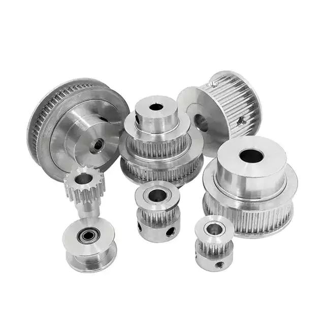
pulley

pulley basic equation

Pulleys work the same way as gravity, so they should withstand similar forces. Newton’s laws of motion can be used to calculate the forces in a pulley system. The second law of motion applies to forces and accelerations. Similar to this is Newton’s third law, which states that the directions of forces are equal and opposite. The fourth law dictates the direction of force. The Fifth Law states that tension is in equilibrium with gravity.
A pulley is a simple mechanism that transmits force by changing direction. They are generally considered to have negligible mass and friction, but this is only an approximation. Pulleys have different uses, from sailboats to farms and large construction cranes. In fact, they are the most versatile mechanisms in any system. Some of their most common applications and equations are listed below.
For example, consider 2 masses m. Those of mass m will be connected by pulleys. The static friction coefficient of the left stop is ms1, and the static friction coefficient of the right stop is ms2. A no-slip equation will contain multiple inequalities. If the 2 blocks are considered to be connected by a pulley, the coefficient of kinetic friction is mk. In other words, the weight of each block carries the same mass, but in the opposite direction.

Types of pulleys

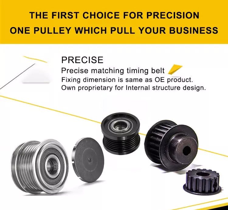
A pulley is a device used to pull and push objects. Pulley systems are ropes, cables, belts or chains. The “drive pulley” is attached to the shaft and moves the driven pulley. They are available in a variety of sizes, and the larger they are, the higher the speed of power transmission. Alternatively, use small pulleys for smaller applications.
Two-wheel pulleys have 2 mechanical advantages. The greater the mechanical advantage, the less force is required to move the object. More wheels lift more weight, but smaller pulleys require less force. In a two-wheel pulley system, the rope is wound around 2 axles and a fixed surface. As you pull on the rope, the shafts above slowly come together.
Compound pulleys have 2 or more rope segments that are pulled up on the load. The mechanical advantage of compound pulleys depends on the number of rope segments and how they are arranged. This type of pulley can increase the force by changing the direction of the rope segment. There are 2 main types of pulleys. Composite pulleys are most commonly used in construction. The ideal mechanical advantage of pulleys is 2 or more.
Construction pulleys are a basic type. They are usually attached to wheel rails and can be lifted to great heights. Combinations of axes are also common. Construction pulleys can be raised to great heights to access materials or equipment. When used in construction, these pulleys are usually made of heavy materials such as wood or metal. They are secured with ropes or chains.

The ideal mechanical advantage of pulleys

The pulley system is a highly complex system with high mechanical advantages. Use a single pulley system to reduce the force required to lift an object by cutting it in half. The mechanical advantage increases as you add more pulleys, such as 6 or seven. To calculate the mechanical advantage of a pulley system, you need to count the number of rope segments between the pulleys. If the free end of the rope is facing down, don’t count it. If it’s facing up, count. Once you have your number, add it up.
The required mechanical advantage of a pulley is the number of rope segments it has to pull the load. The more rope segments, the lower the force. Therefore, the more rope segments the pulley has, the lower the force. If the rope segments are four, then the ideal mechanical advantage is four. In this case, the composite pulley quadrupled the load force.
The ideal mechanical advantage of a pulley system is the sum of the mechanical force and the force required to lift the load at its output. Typically, a single pulley system uses 2 ropes, and the mechanical force required to lift the load is multiplied by the 2 ropes. For a multi-pulley system, the number of ropes will vary, but the total energy requirement will remain the same. The friction between the rope and pulley increases the force and energy required to lift the load, so the mechanical advantage diminishes over time.
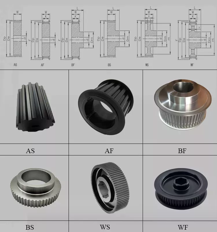
pulley

Common uses of pulley systems

A pulley system is a simple mechanical device typically used to lift heavy objects. It consists of a rotating wheel attached to a fixed shaft and a rope attached to it. When the wheel moves, the force applied by the operator is multiplied by the speed of the pulley, and the force is multiplied by the weight of the object being lifted. Common uses for pulley systems include pulling, lifting, and moving heavy objects.
The oil and petroleum industries use pulley systems in a variety of applications. Most commonly, pulleys are used in drilling operations and they are installed on top of the rig to guide the cable. The cable itself is attached to 2 pulleys suspended in the derrick, where they provide mechanical energy to the cable. Using a pulley system in this application provides the force needed to move the cable safely and smoothly.
The main advantage of the pulley system is that it minimizes the force required to lift an object. The force used to lift the object is multiplied by the desired mechanical advantage. The more rope segments, the lower the force required. On the other hand, a compound pulley system can have many segments. Therefore, a compound pulley system can increase the force a worker can exert on an object.
Safety Precautions to Take When Working on Pulley Systems

There are many safety precautions that should be observed when working on a pulley system. The first is to wear proper protective gear. This includes hard hats that protect you from falling objects. Also, gloves may be required. You should limit the amount of movement in the penalty area, and you should also keep the area free of unnecessary people and objects. Also, remember to wear a hard hat when working on the pulley system.
Another important safety precaution when working on a pulley system is to check the Safe Working Load (SWL) of the pulley before attaching anything. This will help you understand the maximum weight the pulley can hold. Also, consider the angle and height of the pulley system. Always use safety anchors and always remember to wear a hat when working on a pulley system.
Safe use of chain hoists requires training and experience. It is important to read the manufacturer’s manual and follow all safety precautions. If you’re not sure, you can actually inspect the hoist and look for signs of damage or tampering. Look for certifications for sprocket sets and other lifting accessories. Look for the Safe Working Load (SWL) marking on the chain hoist.
pulley

Example of a pulley system

Pulley systems are often used to lift items. It allows you to reduce the effort to lift and move the load by applying force in 1 direction. Pulley systems can be built and modeled to fit any type of project. This resource focuses on pulley systems and is designed to support the new GCSEs in Engineering, Design and Technology. There are also many examples of pulley systems suitable for various applications.
In the study, participants who read easy text took longer to manipulate the pulley system than those who read challenging text. In general, this suggests that participants with prior scientific experience used their cognitive abilities more effectively. Additionally, students who read simple texts spent less time planning the pulley system and more time on other tasks. However, the study did show that the time required to plan the pulley system was similar between the 2 groups.
In everyday life, pulley systems are used to lift various objects. Flagpoles are 1 of many pulley systems used to raise and lower flagpoles. They can also be used to raise and lower garage doors. Likewise, rock climbers use pulleys to help them ascend and descend. The pulley system can also be used to extend the ladder.

China Custom Good Price 14670-97310 Big Shaft 1467097310 High Pressure Tractor Power Steering Pump Nissan Spare Parts for Bus     with Great qualityChina Custom Good Price 14670-97310 Big Shaft 1467097310 High Pressure Tractor Power Steering Pump Nissan Spare Parts for Bus     with Great quality

China factory CNC Machinery Parts Processing Small Hardware Machining Factory Lathe Parts CNC Machining Parts Precision with Great quality

Product Description

Product description

Product name

CNC Machinery Parts 

Color

Buyer’s requirements

Structure

stamping 

Material

Stainless Steel

Surface treatment

Powder Coated

Usage

mounting

Certification

ISO 9001, TS16949

Application

Outdoor

        HangZhou Xihu (West Lake) Dis. Hishen Hardware Co.,Ltd. stands on the beautiful and rich CZPT Port —-HangZhou city, ZHangZhoug province, nearby Xihu (West Lake) Dis. port, train station and high speed way provide a prerequisite for convenient transportation!

         The company established in 2006 , specialize in all kinds of sheet metal fabrication , cnc machining parts , welding parts , stamping parts , tube bending parts and so on . Possess good sustainable development

         infrastructure and strain capacity for quick response to market demand . We carry out ISO9001 Quality Control System in our management .

Quality Control

Packaging & Shipping

Our Team

Our Service

1. OEM/ODM Services, We have engineers to design as buyer’s requirements.
2. Specialized in manufacture metal products, the factory equipped with Cutting machines, punch machines with 10T-60T, plate cutting machines, pipe bending machines, roll bending machine, drilling machine, milling machine, lathe, grander machine, Co2 and argon-arc welding machines, etc.
3. 450m long all automatized metal surface processing plant, all automatized oil wash, rust removing, powder coating, curving, water wash, drying, and other procedures.

FAQ
Q: Are you trading company or manufacturer ?

A: We are factory with ISO  and TS certificate .

Q: How long is your delivery time ?

A: Normaly 30days but it dpends on  . For laser cutting  parts , we can supply it within  10days ,for sheet metal fabrication we can catch  up within 25days . We will always try  our best to  meet customer’s requirment if there is urgency .

Q: Do you provide samples ? Is it free ?

A: Yes , we can offer samples for free if there is no jigs or toolings needed in the production .

Q: What is your payment terms ?

A: Usually we do at 30% TT  as deposit  with  full tooling cost if there is , and the balanace to be paid before shipment after approval of quality . But we  also can offer better terms after we start cooperation  while we have  more know about each other .


What Are Screw Shaft Threads?

A screw shaft is a threaded part used to fasten other components. The threads on a screw shaft are often described by their Coefficient of Friction, which describes how much friction is present between the mating surfaces. This article discusses these characteristics as well as the Material and Helix angle. You’ll have a better understanding of your screw shaft’s threads after reading this article. Here are some examples. Once you understand these details, you’ll be able to select the best screw nut for your needs.
screwshaft

Coefficient of friction between the mating surfaces of a nut and a screw shaft

There are 2 types of friction coefficients. Dynamic friction and static friction. The latter refers to the amount of friction a nut has to resist an opposing motion. In addition to the material strength, a higher coefficient of friction can cause stick-slip. This can lead to intermittent running behavior and loud squeaking. Stick-slip may lead to a malfunctioning plain bearing. Rough shafts can be used to improve this condition.
The 2 types of friction coefficients are related to the applied force. When applying force, the applied force must equal the nut’s pitch diameter. When the screw shaft is tightened, the force may be removed. In the case of a loosening clamp, the applied force is smaller than the bolt’s pitch diameter. Therefore, the higher the property class of the bolt, the lower the coefficient of friction.
In most cases, the screwface coefficient of friction is lower than the nut face. This is because of zinc plating on the joint surface. Moreover, power screws are commonly used in the aerospace industry. Whether or not they are power screws, they are typically made of carbon steel, alloy steel, or stainless steel. They are often used in conjunction with bronze or plastic nuts, which are preferred in higher-duty applications. These screws often require no holding brakes and are extremely easy to use in many applications.
The coefficient of friction between the mating surfaces of t-screws is highly dependent on the material of the screw and the nut. For example, screws with internal lubricated plastic nuts use bearing-grade bronze nuts. These nuts are usually used on carbon steel screws, but can be used with stainless steel screws. In addition to this, they are easy to clean.

Helix angle

In most applications, the helix angle of a screw shaft is an important factor for torque calculation. There are 2 types of helix angle: right and left hand. The right hand screw is usually smaller than the left hand one. The left hand screw is larger than the right hand screw. However, there are some exceptions to the rule. A left hand screw may have a greater helix angle than a right hand screw.
A screw’s helix angle is the angle formed by the helix and the axial line. Although the helix angle is not usually changed, it can have a significant effect on the processing of the screw and the amount of material conveyed. These changes are more common in 2 stage and special mixing screws, and metering screws. These measurements are crucial for determining the helix angle. In most cases, the lead angle is the correct angle when the screw shaft has the right helix angle.
High helix screws have large leads, sometimes up to 6 times the screw diameter. These screws reduce the screw diameter, mass, and inertia, allowing for higher speed and precision. High helix screws are also low-rotation, so they minimize vibrations and audible noises. But the right helix angle is important in any application. You must carefully choose the right type of screw for the job at hand.
If you choose a screw gear that has a helix angle other than parallel, you should select a thrust bearing with a correspondingly large center distance. In the case of a screw gear, a 45-degree helix angle is most common. A helix angle greater than zero degrees is also acceptable. Mixing up helix angles is beneficial because it allows for a variety of center distances and unique applications.
screwshaft

Thread angle

The thread angle of a screw shaft is measured from the base of the head of the screw to the top of the screw’s thread. In America, the standard screw thread angle is 60 degrees. The standard thread angle was not widely adopted until the early twentieth century. A committee was established by the Franklin Institute in 1864 to study screw threads. The committee recommended the Sellers thread, which was modified into the United States Standard Thread. The standardized thread was adopted by the United States Navy in 1868 and was recommended for construction by the Master Car Builders’ Association in 1871.
Generally speaking, the major diameter of a screw’s threads is the outside diameter. The major diameter of a nut is not directly measured, but can be determined with go/no-go gauges. It is necessary to understand the major and minor diameters in relation to each other in order to determine a screw’s thread angle. Once this is known, the next step is to determine how much of a pitch is necessary to ensure a screw’s proper function.
Helix angle and thread angle are 2 different types of angles that affect screw efficiency. For a lead screw, the helix angle is the angle between the helix of the thread and the line perpendicular to the axis of rotation. A lead screw has a greater helix angle than a helical one, but has higher frictional losses. A high-quality lead screw requires a higher torque to rotate. Thread angle and lead angle are complementary angles, but each screw has its own specific advantages.
Screw pitch and TPI have little to do with tolerances, craftsmanship, quality, or cost, but rather the size of a screw’s thread relative to its diameter. Compared to a standard screw, the fine and coarse threads are easier to tighten. The coarser thread is deeper, which results in lower torques. If a screw fails because of torsional shear, it is likely to be a result of a small minor diameter.

Material

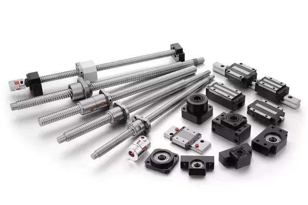
Screws have a variety of different sizes, shapes, and materials. They are typically machined on CNC machines and lathes. Each type is used for different purposes. The size and material of a screw shaft are influenced by how it will be used. The following sections give an overview of the main types of screw shafts. Each 1 is designed to perform a specific function. If you have questions about a specific type, contact your local machine shop.
Lead screws are cheaper than ball screws and are used in light-duty, intermittent applications. Lead screws, however, have poor efficiency and are not recommended for continuous power transmission. But, they are effective in vertical applications and are more compact. Lead screws are typically used as a kinematic pair with a ball screw. Some types of lead screws also have self-locking properties. Because they have a low coefficient of friction, they have a compact design and very few parts.
Screws are made of a variety of metals and alloys. Steel is an economical and durable material, but there are also alloy steel and stainless steel types. Bronze nuts are the most common and are often used in higher-duty applications. Plastic nuts provide low-friction, which helps reduce the drive torques. Stainless steel screws are also used in high-performance applications, and may be made of titanium. The materials used to create screw shafts vary, but they all have their specific functions.
Screws are used in a wide range of applications, from industrial and consumer products to transportation equipment. They are used in many different industries, and the materials they’re made of can determine their life. The life of a screw depends on the load that it bears, the design of its internal structure, lubrication, and machining processes. When choosing screw assemblies, look for a screw made from the highest quality steels possible. Usually, the materials are very clean, so they’re a great choice for a screw. However, the presence of imperfections may cause a normal fatigue failure.
screwshaft

Self-locking features

Screws are known to be self-locking by nature. The mechanism for this feature is based on several factors, such as the pitch angle of the threads, material pairing, lubrication, and heating. This feature is only possible if the shaft is subjected to conditions that are not likely to cause the threads to loosen on their own. The self-locking ability of a screw depends on several factors, including the pitch angle of the thread flank and the coefficient of sliding friction between the 2 materials.
One of the most common uses of screws is in a screw top container lid, corkscrew, threaded pipe joint, vise, C-clamp, and screw jack. Other applications of screw shafts include transferring power, but these are often intermittent and low-power operations. Screws are also used to move material in Archimedes’ screw, auger earth drill, screw conveyor, and micrometer.
A common self-locking feature for a screw is the presence of a lead screw. A screw with a low PV value is safe to operate, but a screw with high PV will need a lower rotation speed. Another example is a self-locking screw that does not require lubrication. The PV value is also dependent on the material of the screw’s construction, as well as its lubrication conditions. Finally, a screw’s end fixity – the way the screw is supported – affects the performance and efficiency of a screw.
Lead screws are less expensive and easier to manufacture. They are a good choice for light-weight and intermittent applications. These screws also have self-locking capabilities. They can be self-tightened and require less torque for driving than other types. The advantage of lead screws is their small size and minimal number of parts. They are highly efficient in vertical and intermittent applications. They are not as accurate as lead screws and often have backlash, which is caused by insufficient threads.

China factory CNC Machinery Parts Processing Small Hardware Machining Factory Lathe Parts CNC Machining Parts Precision     with Great qualityChina factory CNC Machinery Parts Processing Small Hardware Machining Factory Lathe Parts CNC Machining Parts Precision     with Great quality

China Standard Precision Casting Forging CNC Machining Custom Metal Vehicle Spare Part with Best Sales

Product Description

Precision casting forging CNC machining custom metal vehicle spare part

   Muyang machinery is a manufacturer with the capability of comprehensive services of casting, forging and machining, committed to the production of customized parts. Since established in 2002 (former Miaosen Machinery Co., Ltd), we’ve been supplying to the global market for over 15 years, served industries include automotive, railway, gas and oil, medical machinery, construction machinery, gym equipment, etc.

Capability

CNC machining center –

MAX size: 600*1200*500mm

General tolerance: ±0.005mm

Machine qty: 6 sets     

CNC Milling –

MAX size: 1200*500mm

General tolerance: ±0.02mm

Machine qty: 12 sets        

CNC turning –

MAX size: φ0.5-φ800*1000mm

General tolerance: ±0.005mm

Machine qty: 35 sets       

Service:

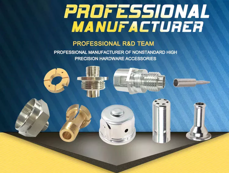
CNC turning, CNC milling, CNC grinding, CNC lathe machining, CNC boring, CNC drilling, CNC tapping, surface treatment etc.

Material available

Stainless steel: SS201, SSS301, SS303, SS304, SS316, SS416, SS440C etc.

Steel: Mild steel, Carbon steel, 4140, 4340, Q235, Q345B, 20#, 45#

Brass/Bronze: HPb63, HPb62, HPb61, HPb59, H59, H68, H80, H90, C360, C260, C932

Copper: C11000, C12000, C36000

Aluminum: AL2017, AL2571, AL5052, AL5083, AL6061, AL6063, AL6082, AL7075

Iron: A36, 45#, 1213, 1214, 1215

Others per customers’ requirements

Surface finish

Aluminum alloy: Clear anodized, color anodized, sand blast anodized, hard anodized, brushing, polishing, powder coated and painting

Brass/copper/steel: Nickel plating, chrome plating

Steel/Stainless steel: Zinc plating, oxide black, carburized, heat treatment, nitriding

Measuring tools

Micrometer, calipers, thread tools, high guage, trapezoidal thread plug gauge, sclerometer, dial indicator, projector


We promise our clients careful, safe and tight package for exporting!

Standard packing: pearl cotton/bubble bag + carton box + pallet/wooden box

Special packingcustom packaging + wooden box
 

FAQ:

1. Are you a manufacturer or trading company?
We’re a manufacturer with self-export rights. 

2. What’s your main business?
Our main business is custom metal parts processed by CNC machining, casting, forging etc., served industries including railway, automobile, construction machinery, gym equipment, water gas and oil.

3. Directly get to CONTACT or send your product drawing/inquiries to email, we will reply within 0.5 hour.


What You Need to Know About Ball Screws

A ball screw is a common industrial component used in various applications. Here’s a basic overview of their features, typical applications, and characteristics. You’ll also learn about their maintenance and repair options. Learn more about ball screws today. We’ve got the answers you’ve been looking for. Scroll down for more information. And be sure to check out our blog for future articles! Until then, enjoy browsing! And happy screwing!
air-compressor

Typical applications

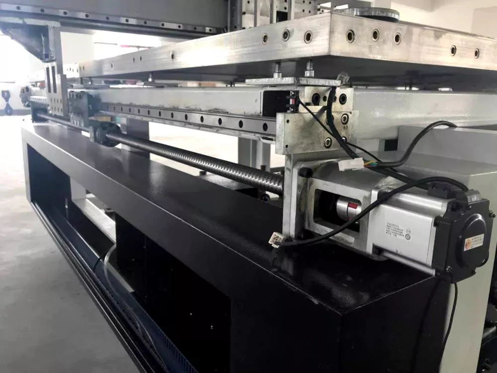
Ball screws are threaded shafts with a ball nut attached to them. These screws operate similar to ball bearings in which hardened steel balls travel a channel. Ball screws are usually used in linear-motion applications because of their high efficiency, load capacity, and positioning accuracy. Although these screws are similar in design to conventional lead screws, ball screws offer some distinct advantages. For example, ball screws are often used in machine tools, step photolithography machines, and microscopic integrated circuits.
For example, the use of larger balls reduces backlash in ball screws by reducing friction between the balls and the grooves. Ball screws can be preloaded using a spring or spacer between 2 ball nuts or a lead with a spherical offset. However, this method requires higher torque and can lead to excessive heat generation. It’s important to consider the size of preload before using a ball screw in a particular application.
Although the ball screws are highly durable, they are not without their disadvantages. For example, their metal-on-metal nature makes them louder than lead screw nuts. For these reasons, proper preloading is vital. Ball screws also have a very low friction coefficient. Ball screws are ideal for applications where backlash is of critical importance, such as wire bonding. A ball screw is the perfect solution for many applications that require precise motion.
Although ball screws are used in a wide variety of applications, they often are exposed to various types of contaminants. Dust, chips, and liquids can interfere with proper lubrication and shorten the lifespan of the ball screw assembly. Ultimately, these contaminants can lead to catastrophic failure of the assembly. They are also prone to abrasive wear and tear. To combat this, it’s important to lubricate your ball screws frequently.

Characteristics

The accuracy of a ball screw is 1 of its primary characteristics, so choosing the correct grade is critical. A ball screw with a C5 accuracy grade is typically used in machining centers, while a C3 or even a C1 screw might be needed for image processing or inspection equipment. Ball screw hardness is also an important consideration, as differences in the Ct and C grades will affect their accuracy. Ultimately, the higher the quality of the ball, the longer its life expectancy.
Numerous studies have been conducted to understand the mechanics of ball screw mechanisms. Cuttino et al. studied the nonlinear torque characteristics of ball screws. Then, by calculating the distribution of loads in all balls, they analyzed the load on the screw shaft and the ball screw.
CZPT has decades of experience in the design and production of ball screws for industrial use. With close to 50 years of know-how, this company is able to respond to a highly-complex market and develop new solutions. Their ball screw ranges range from basic to high-precision. Moreover, they can provide dedicated solutions for specific applications, ensuring the highest quality under all circumstances. And they can meet specific customer needs and requirements thanks to their extensive research and development.
A ball screw must be properly mounted. Improper mounting results in noise and vibration, accelerated wear, and material failure. Also, installed auxiliary components must be checked for faults. And, since ball screw mechanisms are often multi-stage, there are different types of ball screw mechanisms. There are 2 basic types: internal and external recirculation systems. There are many differences between the 2 types, but these 2 types have some fundamental similarities.
air-compressor

Maintenance

Ball screw maintenance can be done easily if you know the symptoms of a deteriorating ball screw. Several signs of deterioration can be detected during regular inspections: excessive vibrations, discoloration, and misalignment of the screw. If the screw is accompanied by excessive noises, there could be a bent screw shaft or misaligned bearing housings. Excessive buildup can also cause clicking noises. If you notice excessive noises from the screw, the return tube has probably been damaged or is broken. Other common symptoms include loss of positioning accuracy due to endplay in support bearings and excessive power consumption.
Another sign of a malfunctioning ball screw is noise, but if you can identify the problem before it occurs, you can flush it. A proper flush can solve any noise or extend the life of the ball screw assembly. Moreover, flushing the assembly can also reveal if the bearings are damaged or galled. If the bearings are broken, you can replace them with new ones. You can also contact a professional to perform PM for ball screw assembly.
A ball screw manufacturer recommends periodic lubrication to maximize uptime. In fact, ball screws are pre-lubricated at the factory, but periodic attention to lubrication is advisable. In addition, the lubrication reservoir must be designed to minimize the loss of lubricant. Finally, the wiper system must be designed to maximize wear protection. It is important to have a wiper system that is capable of sealing the nut and the screw shaft.
To choose a company for your ball screw maintenance, it is important to check their qualifications. The company must have a long-term track record in the servicing of different types of ball screws. Their customer service should include free evaluation. Additionally, the company should offer 3 services: reload, recondition, and replacement. Reload requires cleaning and polishing, reconditioning requires regrinding the ball nut, and replacement means replacing the screw with a new one. If you need a ball screw repair, it is best to contact a professional.

Repair options

A damaged ball screw can shut down a manufacturing line unless the component is repaired quickly. Fortunately, there are several options for repair, including rebuilding, reconditioning, and replacement. Reconditioning and replacement involve remanufacturing the ball screw and ball nut, but both options require new parts. Choosing the best option for your ball screw will depend on how much damage it has suffered and the amount of money it will cost.
In most cases, ball screw repairs can be done on rolled and ground screw types. The process involves eutectic spraying and grinding the screw back to size. Among the 3 repair options, level 4 repair is the most expensive, but it can bring back the lifespan of the screw. Depending on the severity of damage, AB Linear may recommend level 3 repair to repair damaged ball screws. The following process will restore the screw to good working condition.
First, inspect the ball screw for signs of damage. If the ball screw is making unusual noises or vibrations, replace any worn seals or wipers. Discoloration of the ball nut or lead can indicate an inadequate lubrication. Damaged lube lines can also be the cause of a ball screw failure. Repairing these issues is often a cheaper option than purchasing new. By choosing to repair the component instead of replacing it, you will be saving up to 70% of the cost of a replacement ball screw.
If you do experience problems with your ball screw, the best option is to repair it. The cost of replacing a ball screw is prohibitively high, and it can be difficult to find a qualified repair company that specializes in repairing ball screws. A qualified company can repair the ball screw for a small fee. Regardless of the type of screw, it’s always a good idea to seek qualified assistance if it is experiencing any of these problems.
air-compressor

Application in steering systems

The conventional ball screw device is lacking a device to minimize noise and vibration. Both of these factors contribute to reduced performance and durability of a vehicle. The present invention overcomes these shortcomings. A ball screw device with a lower noise and vibration coefficient increases the durability and performance of a vehicle. In addition, it is easier to install and remove than the conventional version. Listed below are some advantages of ball screws in steering systems.
A ball screw is an important component of an automobile’s power steering system. This type of steering system requires a relatively low level of positional repeatability and precision. The screw is rotated by steering wheel motion and a ball nut engages with a Pitman arm. This arm is the primary linkage between the power steering box and the center link. By virtue of its low-cost and high-performance capabilities, ball screws are a desirable choice in many different automotive steering systems.
A ball screw device can be used in any electric power steering system. The shaft of the ball screw is threaded, and a ball nut is installed at its end. The screw includes a damper to reduce noise and vibration. The ball screw is often coupled with a power steering pump and electric motor to control the torque. In the present invention, the ball screw device incorporates a damper. This damper can increase the durability of the ball screw device.
As a leader in the manufacturing of ball screws, CZPT has been in the aerospace industry for decades. Its extensive experience and specialized expertise allows it to meet the diverse needs of the steering system market. Using this technology, CZPT offers a variety of solutions for this complex application. They can provide better positioning accuracy, higher durability and better control. So, if you’re in need of a ball screw in your steering system, contact CZPT today!

China Standard Precision Casting Forging CNC Machining Custom Metal Vehicle Spare Part     with Best SalesChina Standard Precision Casting Forging CNC Machining Custom Metal Vehicle Spare Part     with Best Sales

China supplier The Best Cover Case Bearing Lh Rotavator Spare Parts Used for Dh246f Heavy Plus with high quality

Product Description

Product Description

Hello! My Friends! If you couldn’t find the products you need on our website, you can feel free to contact us, we will reply you as soon as possible. 


Company Profile
 

HangZhou CZPT Imp. & Exp. Co., Ltd. is a comprehensive firm integrating industrial manufacturing with international trade. Over a history of 32 years in business, it has developed a complete operation system, with a leading team of international trade and marketing professionals in the front, and a manufacturing team of high-end research and development technicians and rigid quality control specialists to extend back support. It has a product sample center and logistics warehouse of 3,000 square meters in area.

In order to put into full play its advantages of client and market resources, CZPT selects a number of qualified manufacturers as its reliable production workshops and possesses signed exclusive authority to export their products to overseas markets including Hong Kong, Macao and ZheJiang .

Luckystar has the capacity to manufacture, tailor-make and sell different categories of products covering a wide range of applications. Of all of its business scope, the main and advantaged supply is the following series products.

Agricultural machinery series:
We have developed on our own and manufacture exclusively a series of export-oriented rotary tillers, variable-speed paddy field stubble-bury beaters, foldable paddy field stubble-bury cultivators, and 1GD-350 type paddy field ridge shapers.

Luckystar is specialized in supplying series accessories supporting CZPT and CZPT combines, tractors and tillers among other world recognized brands. Specifically, the following types of spare parts are available in stock.

(1) Components for CZPT harvesters with specifications of DC60, DC68G, 688Q, DC70G, DC70H, DC70PLUS, DC95, and DC105.

(2) Spare parts for CZPT tractors, namely, gears, connecting rods, shafts, hydraulic pumps, clutches, and ball attachments. Relevant specifications cover L1500, L2201, L2202, L2402, L3408, L3608, L4508, L4708, L5018,M6040, M5000, M7040, M8540, M9540, M9000, M105,and M1304.

(3) Components for CZPT tillers with specifications of RX162, RX164, RX180, RX182, and RX220.

(4) Components for CZPT harvesters with specifications of AW70, AW82,AW85, YH700, YH850, and YH880. 

(5) Components for CZPT engines with specifications of D1403, D1503, D1703, V2203, V2403, V3300, V3307, and V3800.

Luckystar has in human resources highly competent talents including international business engineers, adheres to the business phylosophy of credibility, client-centricity and teamwork, and remains dedicated to provide clients with optimum commodities and quality service.

Luckystar highly values and consistently optimizes client service and has so far established long-term cooperation relations with many well-recognized corporations in the world. Our products are exported world wide to the USA, Europe, Japan and South Korea, and in particular, to Thailand, Vietnam, Indonesia, Malaysia, the Phillipines, Egypt, India, Sri Lanka, Myanmar and ZheJiang .

Your selection of us shall be a selection of professionalism.

Luckystar Imp. & Exp. Co., Ltd. cordially welcomes clients, associations and friends both at home and abroad to contact us for business cooperation and mutual benefit. We are looking forward to having you as our next business partner.


FAQ
 

1. Who are we?

We are based in ZheJiang , China, start from 2006,sell to South Asia(8.33%),Northern Europe(8.33%),Central America(8.33%),Western Europe(8.33%),Eastern Asia(8.33%),Mid East(8.33%),Oceania(8.33%),Africa(8.33%),Southeast Asia(8.33%),Eastern Europe(8.33%),South America(8.33%),North America(8.33%). There are total about 11-50 people in our office.

2.How can we guarantee quality?

Always a pre-production sample before mass production;
Always final Inspection before shipment;

3.What can you buy from us?

Various Agricultural Machinery and Spare Parts,Woodworking Machine,Construction Machinery,Oilfield Equipment & spare parts,Abrasive Cloth and Paper

4.Why should you buy from us not from other suppliers?

Our company was established in 2006. We are very professional in ensuring the high quality of products and services. The purpose of our company is to serve our customers wholeheartedly. Customer satisfaction is our grestest pursuit.

5.What services can we provide?

Accepted Delivery Terms: FOB,CFR,CIF;
Accepted Payment Currency:USD;
Accepted Payment Type: T/T;
Language Spoken:English,Chinese


Industrial applications of casing

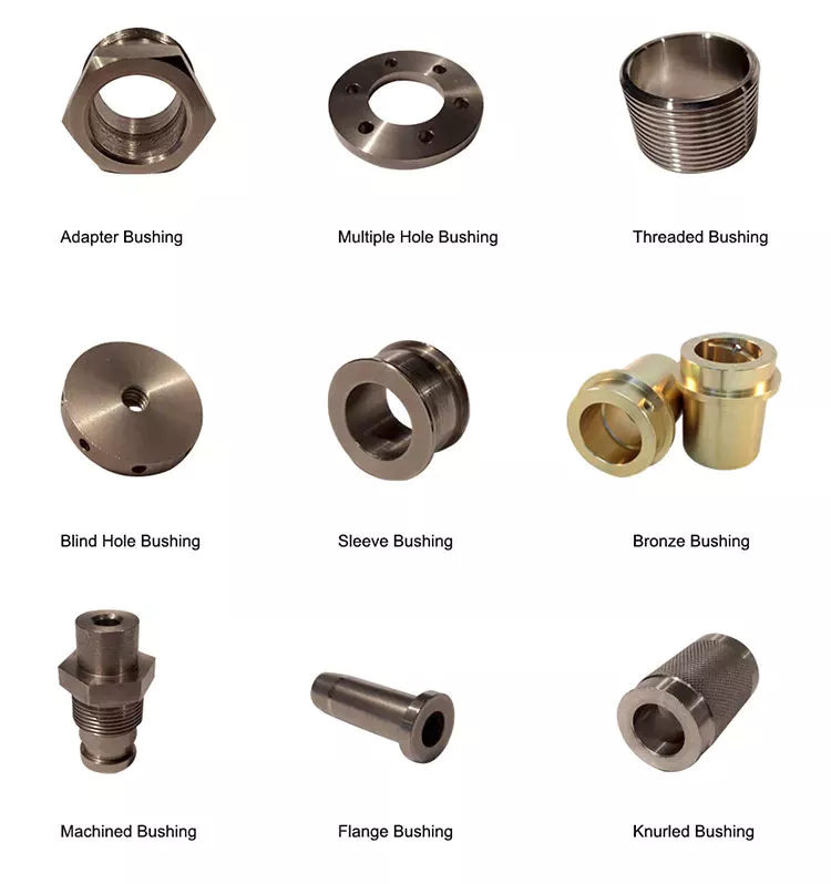
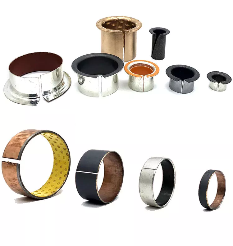
For rotating and sliding parts, bushings are an important part of the machine. Due to their anti-friction properties and load-carrying capacity, they are an important part of many different industrial processes. Bushings play a vital role in industries such as construction, mining, hydropower, agriculture, transportation, food processing and material handling. To learn more about the benefits of bushings, read on. You’ll be amazed how much they can help your business!
bushing

type

When comparing enclosure types, consider the material and how it will be used. Oilite bushings are made of porous material that draws lubricant into the liner and releases it when pressure is applied. These are manufactured using a sintered or powered metal process. Copper and tin are the most commonly used materials for making copper bushings, but there are other types of metal bushings as well.
Another popular type is the plain bearing. This type reduces friction between the rotating shaft and the stationary support element. This type provides support and load bearing while relying on soft metal or plastic for lubrication. Journal bearings are used to support the linear motion of the engine crankshaft in large turbines. They are usually babbitt or hydrodynamic with a liquid film lubricant between the 2 halves.
The oil-impregnated paper sleeve is made of high-quality kraft insulating paper. These bushings contain 2 layers of capacitor grading, with the innermost layer electrically connected to the mounting flange. These are mature processes and are widely used in different voltage levels. CZPT Electric (Group) Co., Ltd. provides UHV DC and AC oil-impregnated paper wall bushings for environmental control rooms.
Electrical bushings are used to transmit electricity. These can be transformers, circuit breakers, shunt reactors and power capacitors. The bushing can be built into the bushing or through the bushing. The conductors must be able to carry the rated current without overheating the adjacent insulation. A typical bushing design has a conductor made of copper or aluminum with insulation on all other sides. If the bushing is used in a circuit, the insulation needs to be high enough to prevent any leakage paths.
Voltage and current ratings of electrical bushings. Solid type electrical bushings typically have a center conductor and a porcelain or epoxy insulator. These bushings are used in small distribution transformers and large generator step-up transformers. Their test voltage is typically around 70 kV. Subsequent applications of this bushing may require a lower halfway release limit. However, this is a common type for many other applications.
bushing

application

Various industrial applications involve the use of casing. It is an excellent mechanical and chemical material with a wide range of properties. These compounds are also packaged according to national and international standards. Therefore, bushings are used in many different types of machines and equipment. This article will focus on the main industrial applications of casing. This article will also explain what a casing is and what it can do. For more information, click here. Casing application
Among other uses, bushing assemblies are used in aircraft and machinery. For example, a fuel tank of an aircraft may include baffle isolator 40 . The bushing assembly 16 serves as an interface to the fuel tank, allowing electrical current to flow. It can also be used to isolate 1 component from another. In some cases, bushing assemblies are used to provide a tight fit and reduce electrical resistance, which is important in circuits.
The benefits of casing go beyond reducing energy transmission. They reduce lubrication costs. If 2 metal parts are in direct contact, lubrication is required. Thus, the bushing reduces the need for lubrication. They also allow parts of the car to move freely. For example, rubber bushings may begin to deteriorate due to high internal temperatures or cold weather. Also, oil can affect their performance.
For example, bushing CTs in oil and gas circuit breakers are used as window current transformers. It consists of a toroidal core and secondary windings. The center conductor of the bushing acts as the single-turn primary of the BCT. By tapping the secondary winding, the ratio between primary and secondary can be changed. This information can be found on the asset nameplate.
Among other uses, bushings are used in diagnostic equipment. These components require precise positioning. Fortunately, air sleeves are perfect for this purpose. Their frictionless operation eliminates the possibility of misalignment. In addition, products based on porous media help minimize noise. A casing manufacturer can advise you on the best product for your equipment. Therefore, if you are looking for replacement bushings for your existing equipment, please feel free to contact Daikin.

Material

Dry ferrule cores were selected for study and examined under an Olympus polarizing microscope (BX51-P). Core slices showing layers of aluminum foil with a distance of approximately 2 cm between adjacent capacitor screens. The aluminum foil surface has a multi-layered structure with undulations due to shrinkage and crepe. Differences between the 2 types of foils are also revealed.
A typical metal bushing material consists of a high-strength metal backing and a solid lubricant. These materials have higher load-carrying capacity and low friction during operation. Additionally, they are precision machined to tight tolerances. They also offer better thermal conductivity and better fatigue resistance. The accuracy of the metal bushing is improved due to the re-machining process that takes place after the bearing is assembled. Additionally, metal bushing materials are more resistant to wear than plastic bushing materials.
Plastic bushings are relatively inexpensive and readily available off the shelf. Also, the price of custom plastic bushings is relatively low. However, they are not recommended for heavy duty applications. Plastics degrade under high loads and can damage mating parts. Also, if the plastic bushings are not manufactured accurately, they can become misaligned. These are just some of the reasons for choosing metal bushings over plastic.
A mechanically bonded bushing 40 is placed over the stabilizer bar and compressed into the outer sleeve/bracket assembly. The outer metal member includes slotted holes that compensate for the tolerance stacking between the first and second bushing assemblies. Pre-assembly allows the assembly plant to receive a complete assembly ready for vehicle assembly, rather than sub-assembly at the vehicle manufacturing plant.
bushing

cost

Control arm bushings are a major component of modern vehicle suspension systems. Damaged bushings can negatively affect the handling and performance of your car. Replacing bushings on a car can cost $200 to $500. While that’s pretty cheap for a handful of control bushings, replacing the entire suspension system could set you back over $1,200. Thankfully, if you want to repair or replace the bushing yourself, you can do it yourself for a fraction of the cost.
If you decide to replace the control arm bushing yourself, it’s best to shop around for the best price. Many auto parts stores offer cheaper bushings that you don’t have to spend a fortune on. Even if you don’t drive for years, rubber can degrade and create cracks in the material. These cracks can be as deep as three-8hs of an inch. This makes it dangerous to drive a car with damaged control arm bushings.
Hiring a mechanic might be a good idea if you don’t like doing the work yourself. You can save money and time by repairing the control arm yourself, but you may have to hire a mechanic to do the job. Replacing the front sway bar bushing alone can cost between $450 and $900. While these components are relatively inexpensive, you can replace them for a better-handling car.
In some cases, sizing the bushings is a more economical option, but if you want to replace your entire suspension system, it’s better to buy a brand new lower limit. You can even save labor by buying a replacement part fork with a good lower portion. In addition to improving your car’s handling and ride, new bushings will add to your car’s overall value. If you are not sure which parts you need, ask your mechanic for a quote.
While the cost of replacing control arm bushings is relatively low, it’s a good idea to compare quotes from multiple mechanics. By getting multiple quotes for the same repair, you can save as much as $50 to $100 on the total cost of your car. In addition to labor costs, parts and labor can vary, so shop around to find the mechanic best suited for your car. There’s no reason to settle for sub-par service when you can save $50 or more!

China supplier The Best Cover Case Bearing Lh Rotavator Spare Parts Used for Dh246f Heavy Plus     with high qualityChina supplier The Best Cover Case Bearing Lh Rotavator Spare Parts Used for Dh246f Heavy Plus     with high quality

China Hot selling The Best Drum Drive Boss 5t051-52242 CZPT Harvester Spare Parts Used for DC60 with high quality

Product Description

Product Description

Hello! My Friends! If you couldn’t find the products you need on our website, you can feel free to contact us, we will reply you as soon as possible. 


Company Profile
 

HangZhou CZPT Imp. & Exp. Co., Ltd. is a comprehensive firm integrating industrial manufacturing with international trade. Over a history of 32 years in business, it has developed a complete operation system, with a leading team of international trade and marketing professionals in the front, and a manufacturing team of high-end research and development technicians and rigid quality control specialists to extend back support. It has a product sample center and logistics warehouse of 3,000 square meters in area.

In order to put into full play its advantages of client and market resources, CZPT selects a number of qualified manufacturers as its reliable production workshops and possesses signed exclusive authority to export their products to overseas markets including Hong Kong, Macao and ZheJiang .

Luckystar has the capacity to manufacture, tailor-make and sell different categories of products covering a wide range of applications. Of all of its business scope, the main and advantaged supply is the following series products.

Agricultural machinery series:
We have developed on our own and manufacture exclusively a series of export-oriented rotary tillers, variable-speed paddy field stubble-bury beaters, foldable paddy field stubble-bury cultivators, and 1GD-350 type paddy field ridge shapers.

Luckystar is specialized in supplying series accessories supporting CZPT and CZPT combines, tractors and tillers among other world recognized brands. Specifically, the following types of spare parts are available in stock.

(1) Components for CZPT harvesters with specifications of DC60, DC68G, 688Q, DC70G, DC70H, DC70PLUS, DC95, and DC105.

(2) Spare parts for CZPT tractors, namely, gears, connecting rods, shafts, hydraulic pumps, clutches, and ball attachments. Relevant specifications cover L1500, L2201, L2202, L2402, L3408, L3608, L4508, L4708, L5018,M6040, M5000, M7040, M8540, M9540, M9000, M105,and M1304.

(3) Components for CZPT tillers with specifications of RX162, RX164, RX180, RX182, and RX220.

(4) Components for CZPT harvesters with specifications of AW70, AW82,AW85, YH700, YH850, and YH880. 

(5) Components for CZPT engines with specifications of D1403, D1503, D1703, V2203, V2403, V3300, V3307, and V3800.

Luckystar has in human resources highly competent talents including international business engineers, adheres to the business phylosophy of credibility, client-centricity and teamwork, and remains dedicated to provide clients with optimum commodities and quality service.

Luckystar highly values and consistently optimizes client service and has so far established long-term cooperation relations with many well-recognized corporations in the world. Our products are exported world wide to the USA, Europe, Japan and South Korea, and in particular, to Thailand, Vietnam, Indonesia, Malaysia, the Phillipines, Egypt, India, Sri Lanka, Myanmar and ZheJiang .

Your selection of us shall be a selection of professionalism.

Luckystar Imp. & Exp. Co., Ltd. cordially welcomes clients, associations and friends both at home and abroad to contact us for business cooperation and mutual benefit. We are looking forward to having you as our next business partner.


FAQ
 

1. Who are we?

We are based in ZheJiang , China, start from 2006,sell to South Asia(8.33%),Northern Europe(8.33%),Central America(8.33%),Western Europe(8.33%),Eastern Asia(8.33%),Mid East(8.33%),Oceania(8.33%),Africa(8.33%),Southeast Asia(8.33%),Eastern Europe(8.33%),South America(8.33%),North America(8.33%). There are total about 11-50 people in our office.

2.How can we guarantee quality?

Always a pre-production sample before mass production;
Always final Inspection before shipment;

3.What can you buy from us?

Various Agricultural Machinery and Spare Parts,Woodworking Machine,Construction Machinery,Oilfield Equipment & spare parts,Abrasive Cloth and Paper

4.Why should you buy from us not from other suppliers?

Our company was established in 2006. We are very professional in ensuring the high quality of products and services. The purpose of our company is to serve our customers wholeheartedly. Customer satisfaction is our grestest pursuit.

5.What services can we provide?

Accepted Delivery Terms: FOB,CFR,CIF;
Accepted Payment Currency:USD;
Accepted Payment Type: T/T;
Language Spoken:English,Chinese


The benefits of using pulleys

A pulley is a mechanical device that converts force into rotation. There are many advantages to using pulleys. Let’s take a look at a few of them. This article will describe the advantages, types, applications, and power sources of pulleys. You can then choose the pulley that best suits your specific needs. If you’re looking for a new tool to help you with a certain task, this article is for you.
pulley

Mechanical advantage

The mechanical advantage of a pulley can be defined as the ratio of applied force to the applied force. The mechanical advantage of a pulley can be calculated by considering several factors, including weight and friction. It can be calculated by the force applied per unit length of rope and the number of pulleys used. In a single-circuit system, the force required to lift a heavy object is equal to the user’s body weight.
The mechanical advantage of a pulley can be realized by comparing it to a seesaw. Both uses of rope are suitable for lifting objects. A rope 4 times heavier than a kilo is 4 times as effective. Because the forces on both sides of the pulley are equal, a small force is enough to move a large weight a short distance. The same force can be applied to a large mass to lift it several meters.
After introducing the concept of mechanical advantage, learners will practice using the pulley system. In addition to testing the pulley system, they should also calculate its mechanical advantage. Using either the instructor-provided handout or the learner’s workbook, students will determine how easily the pulley system functions. Once they have completed the test, they can discuss their results and how the system can be improved. These courses are best completed as part of a mini-unit or as a standalone main course.
The mechanical advantage of the pulley system is proportional to the number of rope loops. This circuit requires the same force as the dual circuit to lift heavy objects. A single lap requires only a third of the force to lift a double lap, while 3 laps require almost half the energy required for a single lap. The mechanical advantage of the pulley system becomes constant as the number of cycles increases.
The 3:1 Mechanical Advantage system feels like lifting a 300-pound load with 3 feet of rope. The three-foot-long rope moves the load 1 foot high. Understanding the mechanical advantages of pulleys is critical for rescuers when trying to create the perfect pulley system. Ideally, the pulley system will be anchored to a nearby rock, tree, pole or person – if the weight is not too heavy.
pulley

Types of pulleys

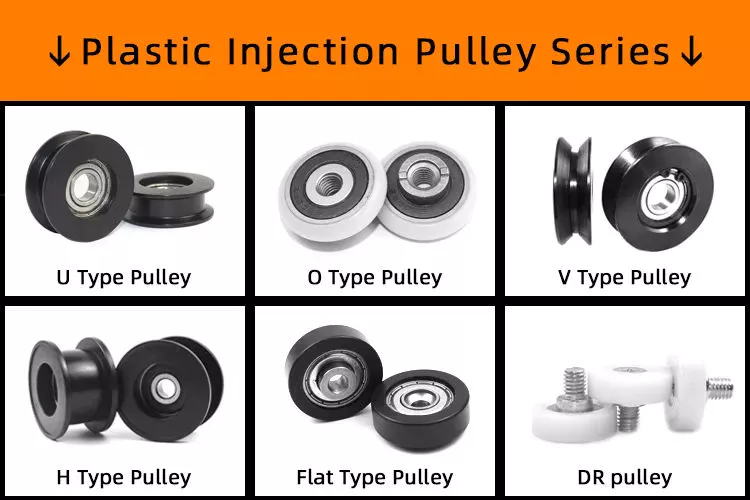
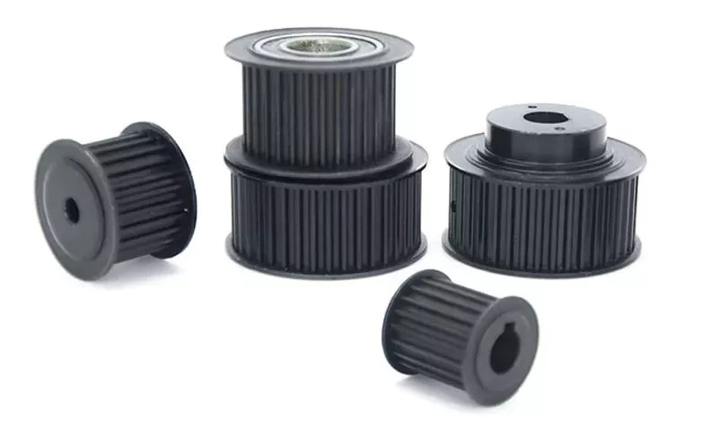
There are several types of pulleys. V-belt pulleys are the type commonly used in vehicles and electric motors. “V” pulleys require a “V” belt, and some even have multiple V grooves. “V” pulleys are often used in heavy duty applications for power transmission because they reduce the risk of power slippage.
Composite pulleys combine the properties of fixed and movable pulleys. Compound pulleys are able to change the direction of force while requiring relatively low force to move even the heaviest loads. Mechanical advantage is a measure of the effectiveness of a machine or equipment. It can be divided into 3 categories: force, distance and mechanics. Once you understand how each type works, you can design complex machines.
Fixed pulleys: These pulleys are the most basic type of pulleys. They use ropes and slotted wheels to move with the lifted object. Because they are so simple to set up, lifting heavy objects is a breeze. Although the moving object feels light, it is actually heavier than it actually is. These pulleys are used in construction cranes, utility elevators and many different industries.
Compound Pulley System: A pulley pulley is a combination of 2 fixed pulleys and 1 movable pulley. Compound pulley systems are effective for moving heavy objects because they have the largest force multipliers and are flexible enough to change the direction of the force as needed. Composite pulley systems are commonly used in rock climbing, theater curtains and sailing. If you’re looking for a pulley system, you can start by evaluating the types of pulleys and their uses.
Construction Pulleys: These are the most basic types of pulleys and have wheel rails. These pulleys can be lifted to great heights and attached to chains or ropes. They allow workers to access equipment or materials from greater heights. They are usually mounted on wheels with axles and secured with ropes. They are essential tools for construction workers. There are many different types of pulleys out there.

energy source

Belts and pulleys are mechanical devices used to transmit energy and rotational motion. The belt is connected to the rotating part of the energy source, and the pulley is mounted on the other. One pulley transmits power to the other, while the other changes the direction of the force. Many devices use this combination, including automobiles, stationary generators, and winches. It is used in many home applications, from conveyors to treadmills. Pulleys are also used for curtains in theater halls.
Pulley systems are an essential part of modern industry and everyday life. Pulleys are used in elevators, construction sites and fitness equipment. They are also used in belt-driven generators as backup power. Despite their simple and seemingly humble beginnings, they have become a versatile tool. From lifting heavy objects to guiding wind turbines, pulley systems are widely used in our daily lives.
The main reason why pulleys are so popular is the mechanical advantage they offer. They can lift a lot of weight by applying very little force over longer distances. For example, a small motor can pull 10 meters of cable, while a large motor can pull 1 meter. Also, the work done is equal to the force times the distance traveled, so the energy delivered to the large motor is the same.
The power source for the pulley system can be cables, belts or ropes. The drive element in a pulley system is usually a rope or cable. A belt is a loop of flexible material that transmits motion from 1 pulley to another. The belt is attached to the shaft and a groove is cut in the pulley. The belt then transfers energy from 1 pulley to the other through the system.
pulley

application

A pulley is a mechanical device used to lift heavy objects. They reduce the amount of work required to lift heavy objects and are an excellent choice for many applications. There are several different applications for pulleys, including elevators, grinders, planters, ladder extensions, and mountaineering or rock climbing. Let’s take a look at some of the most popular uses for pulleys in modern society. These include:-
A pulley is a mechanical device that changes force. To use, you wrap the rope around it and pull down to lift the object. While this device is very useful, a major limitation of using pulleys is that you still have to apply the same force to lift the object as you would without the pulleys. This is why people use pulleys to move large objects like furniture and cars.
In addition to lifting heavy objects, pulleys are used in elevators, flagpoles and wells. These systems allow people to move heavy objects without straining their backs. Many other examples of pulleys in the home include garage doors, flagpoles, and elevators. They also help raise and lower flagpoles, which can reach several stories high.
There are 2 basic types of pulleys: movable and fixed. Fixed pulleys are attached to a ceiling or other object using 2 ropes. Modern elevators and construction cranes use movable pulleys, as do some weight machines in gyms. Composite pulleys combine movable and fixed pulleys to minimize the force required to move heavy objects.
Another type of fixed pulley is the flagpole. A flagpole can support a country, organization, or anything else that needs to be lifted. A taller flagpole creates a prouder moment for those who support it. The operation of the rope and pulley mechanism is very simple. The user simply attaches the flag to the rope, pulls the pulley, and he or she can watch the flag rise and unfold.

China Hot selling The Best Drum Drive Boss 5t051-52242 CZPT Harvester Spare Parts Used for DC60     with high qualityChina Hot selling The Best Drum Drive Boss 5t051-52242 CZPT Harvester Spare Parts Used for DC60     with high quality

China Custom Jcb Spare Parts for Backhoe Loader 3cx and 4cx Filter 32/925371 716/30077 701/E6430 331/43119 30/925685 30/925975 with Great quality

Product Description

JCB SPARE PARTS Backhoe loader 3cx and 4cx  FILTER 32/925371

Q1. What is your terms of packing?
A: Generally, we pack our goods in neutral white boxes and brown cartons. If you have legally registered patent, 
we can pack the goods in your branded boxes after getting your authorization letters.

Q2. What is your terms of payment?
A: T/T 30% as deposit, and 70% before delivery. We’ll show you the photos of the products and packages 
before you pay the balance.

Q3. What is your terms of delivery?
A: EXW, FOB, CFR, CIF, DDU.

Q4. How about your delivery time?
1) 1-2 days if goods in stock.
2) 10-20 days if goods out of stock with molding.
3) 25-35 days if goods out of stock without molding.

Q5. Can you produce according to the samples?
A: Yes, we can produce by your samples or technical drawings. We can build the molds and fixtures.

Q6. What is your sample policy?
A: We can supply the sample if we have ready parts in stock, but the customers have to pay the sample cost and 
the courier cost.

Q7. Do you test all your goods before delivery?
A: Yes, we have 100% test before delivery

Q8: How do you make our business long-term and good relationship?
A:1. We keep good quality and competitive price to ensure our customers benefit ;
2. We respect every customer as our friend and we sincerely do business and make friends with them, 
no matter where they come from.

01/117901 BELT
01/124404 BELT
01/124405 BELT
01/130301 BELT
02/100073 Filter
02/100078 GEAR
02/100192 Thermostat
02/15714 Filter
02/101327 BELT
02/101435 seal
02/101436 SEAL
02/101440 ROD
02/101566 BELT
02/101906 BELT
02/157140 WATER PUMP
02/157161 WATER PUMP
02/192002 BEARING
02/192003 BEARING
02/192004 BEARING
02/192005 BEARING
02/200002 CYLINDER
02/20571 BEARING
02/200018 PULLEY
02/200113 Connector
02/200114 cooler
02/200120 Cooler oil
02/200173 SEAL KITS
02/200192 PISTON RING
02/20571 Hub Fan Drive
02/200460 TURBO
02/200502 Elbow turbo exhaust 
02/200503 BUSH
02/200521 BELT
02/2571 GASKET
02/20 0571 GASKET
02/20571 PULLEY
02/200904 PISTON
02/2571 CRANKSHAFT
02/257150 GEAR PUMP
02/201140 PISTON RING
02/201141 CYLINDER
02/201142 Liner slip-fit
02/201291 BELT
02/201318 Connector water outlet
02/201328 PULLEY
02/201343 CAP
02/201357 Hub Fan Drive
02/201406 Connector
02/201452 Valve oil relief
02/201457 WATER PUMP
02/201504 PISTON RING
02/201505 PISTON
02/201539 GASKET WATER PUMP
02/201729 GASKET
02/201804 PISTON RING
02/201805 PISTON
02/201823 TIMING CASE
02/201849 GASKET
02/201852 TIMING COVER
02/201858 Elbow turbo exhaust
02/257107 Thermostat
02/257117 Breather
02/257145 PISTON
02/257174 TIMING CASE
02/257170 SEAL
02/257100 TURBO
02/257111 Connector water outlet
02/257167 Connector water outlet
02/257180 WATER PUMP
02/257184 HOUSING
02/257185 GEAR PUMP
02/257110 WATER PUMP
02/257124 GASKET
02/257110 CRANKSHAFT
02/257115 BEARING
02/257116 BEARING
02/257117 BEARING
02/257118 BEARING
02/257120 PISTON
02/257121 PISTON RING
02/257122 ROD
02/257135 SEAL
02/257162 HOUSING
02/257178 GASKET KITS
02/257180 Connector water inlet
02/257183 GASKET
02/257194 GASKET KITS
02/257199 GASKET KITS
02/203002 COOLER GASKET
02/2571 Elbow exhaust
02/203017 Gasket exhaust manifold
02/203056 CYLINDER KITS
02/25716 COOLER
02/25716 Top Gasket RG
02/2 0571 0 TURBO
02/2 0571 6 CYLINDER KITS
02/2 0571 4 Connector water outlet assembly vertical
02/2 0571 5 THERMO
02/2 0571 6 THERMOSTAT
02/203218 COOLER GASKET
02/203237 Cover Ciover timing
02/203246 TIMNING CASE
02/634780 LIFT PUMP
02/800571 filter
02/805712 BELT
02/857110 water pump
02/91 0571 filter
02/971635 filter
04/55710 TORQUE CONVERNT
04/55716 Friction
04/55717 Friction
04/505717 GEAR PUMP
04/505719 FRICTION
04/55711 Friction
04/55713 FRICTION
04/55715 FRICTION
04/500300 Friction
04/500800 TORQUE
04/501400 TORQUE
04/501700 Friction
04/501800 TORQUE CONVERNT
04/600650 TORQUE CONVERNT
04/600784 TORQUE
04/600786 TORQUE CONVERNT
04/6 4 DISC
05/206000 Bearing roller
05/206300 Shaft
05/900308 SEAL KITS
05/901926 Pad thrust
05/903801 JS220 GEAR
05/903804 Gear sun
05/903805 Gear reduction set 1st planet
05/903806 Gear reduction set 2nd planet
05/903808 Gear planet
05/903811 Seal assembly
05/903819 O Ring
05/903823 Gear sun
05/903825 Gear reduction set 1st planet
05/903854 Coupling
05/903860 Gear reduction assembly
05/903862 Ring Toothed
05/903865 Ring Toothed
05/903866 Gear Reduction Assembly
05/903867 Gear Sun
05/903869 Shaft pinion 14 teeth
05/903872 Bearing
05/9 0571 3 Sun Gear(Swing 2nd)
106/40001 BOLT
109/55715 SHAFT
111/35711 ENGINE MOUNTING
116/00525 CLIP
120/30002 COTTER PIN
120/30003 SHAFT
120/38003 SPACER
120/40301 PISTON HOUSIN
120/93201 HANDLE
120/93202 HANDLE
1207/0017 Bush
1207/0019 Bush
1208/0015 Bush
1208/0017 Bush
1208/0018 Bush
1208/571 Bush
1208/0571 Bush
1208/0571 Bush
1208/571 Bush
1208/0031 Bush
1208/0032 Bush
1209/0019 Bush
1209/571 Bush
1209/0571 Bush
1209/571 Bush
1209/0571 Bush
1209/0026 BUSH
121/13400 LOCK
121/13500 LOCK DOOR
121/34400 Tractor Parts(Plastic etc.,)
121/59400 MIRROR
121/59800 TANK

How to Replace a Bearing

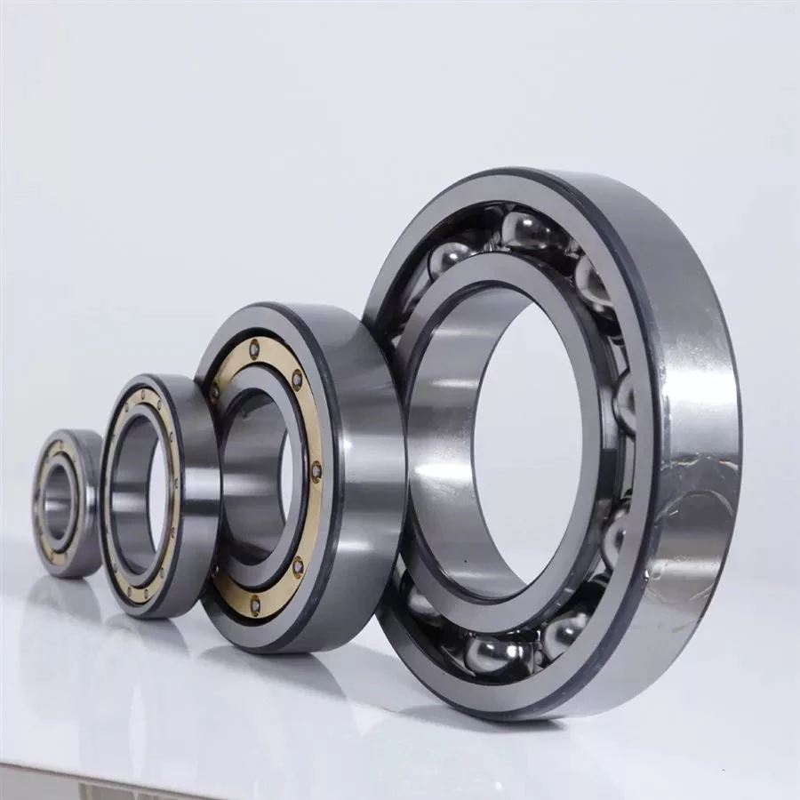
If you want to select a bearing for a specific application, you should know a few basics. This article will give you an overview of ball, angular contact, and sliding-contact bearings. You can choose a bearing according to the application based on the characteristics of its material and preload. If you are not sure how to choose a bearing, try experimenting with it. The next step is to understand the Z-axis, which is the axes along which the bearing moves.

Z axis

When it comes to replacing your Z axis bearing, there are several things you must know. First, you need to make sure that the bearings are seated correctly. Then, you should check the tension and rotation of each one. To ensure that both bearings are equally tensioned, you should flex the Core to the desired angle. This will keep the Z axis perpendicular to the work surface. To do this, first remove the Z axis bearing from its housing and insert it into the Z axis motor plate. Next, insert the flanged bearing into the Z axis motor plate and secure it with 2 M5x8mm button head cap screws.
Make sure that the bearing plate and the Z Coupler part are flush and have equal spacing. The spacing between the 2 parts is important, as too much spacing will cause the leadscrew to become tight. The screws should be very loose, with the exception of the ones that engage the nylocks. After installing the bearing, the next step is to start the Z axis. Once this is done, you’ll be able to move it around with a stepper.

Angular contact

bearing
Ball bearings are made with angular contacts that result in an angle between the bearing’s races. While the axial load moves in 1 direction through the bearing, the radial load follows a curved path, tending to separate the races axially. In order to minimize this frictional effect, angular contact bearings are designed with the same contact angle on the inner and outer races. The contact angle must be chosen to match the relative proportions of the axial and radial loads. Generally, a larger contact angle supports a higher axial load, while reducing radial load.
Ball bearings are the most common type of angular contact bearings. Angular contact ball bearings are used in many applications, but their primary purpose is in the spindle of a machine tool. These bearings are suitable for high-speed, precision rotation. Their radial load capacity is proportional to the angular contact angle, so larger contact angles tend to enlarge with speed. Angular contact ball bearings are available in single and double-row configurations.
Angular contact ball bearings are a great choice for applications that involve axial loads and complex shapes. These bearings have raceways on the inner and outer rings and mutual displacement along the axial axis. Their axial load bearing capacity increases as the contact Angle a rises. Angular contact ball bearings can withstand loads up to 5 times their initial weight! For those who are new to bearings, there are many resources online dedicated to the subject.
Despite their complexity, angular contact ball bearings are highly versatile and can be used in a wide range of applications. Their angular contact enables them to withstand moderate radial and thrust loads. Unlike some other bearings, angular contact ball bearings can be positioned in tandem to reduce friction. They also feature a preload mechanism that removes excess play while the bearing is in use.
Angular contact ball bearings are made with different lubricants and cage materials. Standard cages for angular contact ball bearings correspond to Table 1. Some are machined synthetic resins while others are molded polyamide. These cage materials are used to further enhance the bearing’s axial load capacity. Further, angular contact ball bearings can withstand high speeds and radial loads. Compared to radial contact ball bearings, angular contact ball bearings offer the greatest flexibility.

Ball bearings

bearing
Ball bearings are circular structures with 2 separate rings. The smaller ring is mounted on a shaft. The inner ring has a groove on the outer diameter that acts as a path for the balls. Both the inner and outer ring surfaces are finished with very high precision and tolerance. The outer ring is the circular structure with the rolling elements. These elements can take many forms. The inner and outer races are generally made of steel or ceramic.
Silicon nitride ceramic balls have good corrosion resistance and lightweight, but are more expensive than aluminum oxide balls. They also exhibit an insulating effect and are self-lubricating. Silicon nitride is also suitable for high-temperature environments. However, this type of material has the disadvantage of wearing out rapidly and is prone to cracking and shattering, as is the case with bearing steel and glass. It’s also less resistant to heat than aluminum oxide, so it’s best to buy aluminum nitride or ceramic ball bearings for applications that are subjected to extremely high temperatures.
Another type of ball bearings is the thrust bearing. It has a special design that accommodates forces in both axial and radial directions. It is also called a bidirectional bearing because its races are side-by-side. Axial ball bearings use a side-by-side design, and axial balls are used when the loads are transmitted through the wheel. However, they have poor axial support and are prone to separating during heavy radial loads.
The basic idea behind ball bearings is to reduce friction. By reducing friction, you’ll be able to transfer more energy, have less erosion, and improve the life of your machine. With today’s advances in technology, ball bearings can perform better than ever before. From iron to steel to plastics, the materials used in bearings have improved dramatically. Bearings may also incorporate an electromagnetic field. So, it’s best to select the right 1 for your machine.
The life expectancy of ball bearings depends on many factors, including the operating speed, lubrication, and temperature. A single million-rpm ball bearing can handle between 1 and 5 million rotations. As long as its surface contact area is as small as possible, it’s likely to be serviceable for at least 1 million rotations. However, the average lifespan of ball bearings depends on the application and operating conditions. Fortunately, most bearings can handle a million or more rotations before they start showing signs of fatigue.

Sliding-contact bearings

bearing
The basic principle behind sliding-contact bearings is that 2 surfaces move in contact with 1 another. This type of bearing works best in situations where the surfaces are made of dissimilar materials. For instance, a steel shaft shouldn’t run in a bronze-lined bore, or vice versa. Instead, 1 element should be harder than the other, since wear would concentrate in that area. In addition, abrasive particles tend to force themselves into the softer surface, causing a groove to wear in that part.
Sliding-contact bearings have low coefficients of friction and are commonly used in low-speed applications. Unlike ball and roller bearings, sliding contact bearings have to be lubricated on both sides of the contacting surfaces to minimize wear and tear. Sliding-contact bearings generally are made of ceramics, brass, and polymers. Because of their lower friction, they are less accurate than rolling-element bearings.
Sliding-contact bearings are also known as plain or sleeve bearings. They have a sliding motion between their 2 surfaces, which is reduced by lubrication. This type of bearing is often used in rotary applications and as guide mechanisms. In addition to providing sliding action, sliding-contact bearings are self-lubricating and have high load-carrying capacities. They are typically available in 2 different types: plain bearings and thrust bearings.
Sliding-contact linear bearing systems consist of a moving structure (called the carriage or slide) and the surfaces on which the 2 elements slide. The surfaces on which the bearing and journal move are called rails, ways, or guides. A bore hole is a complex geometry, and a minimum oil film thickness h0 is usually used at the line of centers. It is possible to have a sliding-contact bearing in a pillow block.
Because these bearings are porous, they can absorb 15 to 30% of the lubrication oil. This material is commonly used in automobile and machine tools. Many non-metallic materials are used as bearings. One example is rubber, which offers excellent shock absorbency and embeddability. While rubber has poor strength and thermal conductivity, it is commonly used in deep-well pumps and centrifugal pumps. This material has high impact strength, but is not as rigid as steel.

China Custom Jcb Spare Parts for Backhoe Loader 3cx and 4cx Filter 32/925371 716/30077 701/E6430 331/43119 30/925685 30/925975     with Great qualityChina Custom Jcb Spare Parts for Backhoe Loader 3cx and 4cx Filter 32/925371 716/30077 701/E6430 331/43119 30/925685 30/925975     with Great quality

China best Jcb Spare Parts for Backhoe Loader 3cx and 4cx Filter 02/912210 834/10817 834/11198 834/11380 834/00450 834/00528 with Good quality

Product Description

JCB SPARE PARTS Backhoe loader 3cx and 4cx  FILTER 02/912210

Q1. What is your terms of packing?
A: Generally, we pack our goods in neutral white boxes and brown cartons. If you have legally registered patent, 
we can pack the goods in your branded boxes after getting your authorization letters.

Q2. What is your terms of payment?
A: T/T 30% as deposit, and 70% before delivery. We’ll show you the photos of the products and packages 
before you pay the balance.

Q3. What is your terms of delivery?
A: EXW, FOB, CFR, CIF, DDU.

Q4. How about your delivery time?
1) 1-2 days if goods in stock.
2) 10-20 days if goods out of stock with molding.
3) 25-35 days if goods out of stock without molding.

Q5. Can you produce according to the samples?
A: Yes, we can produce by your samples or technical drawings. We can build the molds and fixtures.

Q6. What is your sample policy?
A: We can supply the sample if we have ready parts in stock, but the customers have to pay the sample cost and 
the courier cost.

Q7. Do you test all your goods before delivery?
A: Yes, we have 100% test before delivery

Q8: How do you make our business long-term and good relationship?
A:1. We keep good quality and competitive price to ensure our customers benefit ;
2. We respect every customer as our friend and we sincerely do business and make friends with them, 
no matter where they come from.

02/257120 PISTON
02/257121 PISTON RING
02/257122 ROD
02/257135 SEAL
02/257162 HOUSING
02/257178 GASKET KITS
02/257180 Connector water inlet
02/257183 GASKET
02/257194 GASKET KITS
02/257199 GASKET KITS
02/203002 COOLER GASKET
02/2571 Elbow exhaust
02/203017 Gasket exhaust manifold
02/203056 CYLINDER KITS
02/25716 COOLER
02/25716 Top Gasket RG
02/2 0571 0 TURBO
02/2 0571 6 CYLINDER KITS
02/2 0571 4 Connector water outlet assembly vertical
02/2 0571 5 THERMO
02/2 0571 6 THERMOSTAT
02/203218 COOLER GASKET
02/203237 Cover Ciover timing
02/203246 TIMNING CASE
02/634780 LIFT PUMP
02/800571 filter
02/805712 BELT
02/857110 water pump
02/91 0571 filter
02/971635 filter
04/55710 TORQUE CONVERNT
04/55716 Friction
04/55717 Friction
04/505717 GEAR PUMP
04/505719 FRICTION
04/55711 Friction
04/55713 FRICTION
04/55715 FRICTION
04/500300 Friction
04/500800 TORQUE
04/501400 TORQUE
04/501700 Friction
04/501800 TORQUE CONVERNT
04/600650 TORQUE CONVERNT
04/600784 TORQUE
04/600786 TORQUE CONVERNT
04/6 4 DISC
05/206000 Bearing roller
05/206300 Shaft
05/900308 SEAL KITS
05/901926 Pad thrust
05/903801 JS220 GEAR
05/903804 Gear sun
05/903805 Gear reduction set 1st planet
05/903806 Gear reduction set 2nd planet
05/903808 Gear planet
05/903811 Seal assembly
05/903819 O Ring
05/903823 Gear sun
05/903825 Gear reduction set 1st planet
05/903854 Coupling
05/903860 Gear reduction assembly
05/903862 Ring Toothed
05/903865 Ring Toothed
05/903866 Gear Reduction Assembly
05/903867 Gear Sun
05/903869 Shaft pinion 14 teeth
05/903872 Bearing
05/9 0571 3 Sun Gear(Swing 2nd)
106/40001 BOLT
109/55715 SHAFT
111/35711 ENGINE MOUNTING
116/00525 CLIP
120/30002 COTTER PIN
120/30003 SHAFT
120/38003 SPACER
120/40301 PISTON HOUSIN
120/93201 HANDLE
120/93202 HANDLE

01/117901 BELT
01/124404 BELT
01/124405 BELT
01/130301 BELT
02/100073 Filter
02/100078 GEAR
02/100192 Thermostat
02/15714 Filter
02/101327 BELT
02/101435 seal
02/101436 SEAL
02/101440 ROD
02/101566 BELT
02/101906 BELT
02/157140 WATER PUMP
02/157161 WATER PUMP
02/192002 BEARING
02/192003 BEARING
02/192004 BEARING
02/192005 BEARING
02/200002 CYLINDER
02/20571 BEARING
02/200018 PULLEY
02/200113 Connector
02/200114 cooler
02/200120 Cooler oil
02/200173 SEAL KITS
02/200192 PISTON RING
02/20571 Hub Fan Drive
02/200460 TURBO
02/200502 Elbow turbo exhaust 
02/200503 BUSH
02/200521 BELT
02/2571 GASKET
02/20 0571 GASKET
02/20571 PULLEY
02/200904 PISTON
02/2571 CRANKSHAFT
02/257150 GEAR PUMP
02/201140 PISTON RING
02/201141 CYLINDER
02/201142 Liner slip-fit
02/201291 BELT
02/201318 Connector water outlet
02/201328 PULLEY
02/201343 CAP
02/201357 Hub Fan Drive
02/201406 Connector
02/201452 Valve oil relief
02/201457 WATER PUMP
02/201504 PISTON RING
02/201505 PISTON
02/201539 GASKET WATER PUMP
02/201729 GASKET
02/201804 PISTON RING
02/201805 PISTON
02/201823 TIMING CASE
02/201849 GASKET
02/201852 TIMING COVER
02/201858 Elbow turbo exhaust
02/257107 Thermostat
02/257117 Breather
02/257145 PISTON
02/257174 TIMING CASE
02/257170 SEAL
02/257100 TURBO
02/257111 Connector water outlet
02/257167 Connector water outlet
02/257180 WATER PUMP
02/257184 HOUSING
02/257185 GEAR PUMP
02/257110 WATER PUMP
02/257124 GASKET
02/257110 CRANKSHAFT
02/257115 BEARING
02/257116 BEARING
02/257117 BEARING
02/257118 BEARING

Driveshaft structure and vibrations associated with it

The structure of the drive shaft is critical to its efficiency and reliability. Drive shafts typically contain claw couplings, rag joints and universal joints. Other drive shafts have prismatic or splined joints. Learn about the different types of drive shafts and how they work. If you want to know the vibrations associated with them, read on. But first, let’s define what a driveshaft is.
air-compressor

transmission shaft

As the demand on our vehicles continues to increase, so does the demand on our drive systems. Higher CO2 emission standards and stricter emission standards increase the stress on the drive system while improving comfort and shortening the turning radius. These and other negative effects can place significant stress and wear on components, which can lead to driveshaft failure and increase vehicle safety risks. Therefore, the drive shaft must be inspected and replaced regularly.
Depending on your model, you may only need to replace 1 driveshaft. However, the cost to replace both driveshafts ranges from $650 to $1850. Additionally, you may incur labor costs ranging from $140 to $250. The labor price will depend on your car model and its drivetrain type. In general, however, the cost of replacing a driveshaft ranges from $470 to $1850.
Regionally, the automotive driveshaft market can be divided into 4 major markets: North America, Europe, Asia Pacific, and Rest of the World. North America is expected to dominate the market, while Europe and Asia Pacific are expected to grow the fastest. Furthermore, the market is expected to grow at the highest rate in the future, driven by economic growth in the Asia Pacific region. Furthermore, most of the vehicles sold globally are produced in these regions.
The most important feature of the driveshaft is to transfer the power of the engine to useful work. Drive shafts are also known as propeller shafts and cardan shafts. In a vehicle, a propshaft transfers torque from the engine, transmission, and differential to the front or rear wheels, or both. Due to the complexity of driveshaft assemblies, they are critical to vehicle safety. In addition to transmitting torque from the engine, they must also compensate for deflection, angular changes and length changes.

type

Different types of drive shafts include helical shafts, gear shafts, worm shafts, planetary shafts and synchronous shafts. Radial protruding pins on the head provide a rotationally secure connection. At least 1 bearing has a groove extending along its circumferential length that allows the pin to pass through the bearing. There can also be 2 flanges on each end of the shaft. Depending on the application, the shaft can be installed in the most convenient location to function.
Propeller shafts are usually made of high-quality steel with high specific strength and modulus. However, they can also be made from advanced composite materials such as carbon fiber, Kevlar and fiberglass. Another type of propeller shaft is made of thermoplastic polyamide, which is stiff and has a high strength-to-weight ratio. Both drive shafts and screw shafts are used to drive cars, ships and motorcycles.
Sliding and tubular yokes are common components of drive shafts. By design, their angles must be equal or intersect to provide the correct angle of operation. Unless the working angles are equal, the shaft vibrates twice per revolution, causing torsional vibrations. The best way to avoid this is to make sure the 2 yokes are properly aligned. Crucially, these components have the same working angle to ensure smooth power flow.
The type of drive shaft varies according to the type of motor. Some are geared, while others are non-geared. In some cases, the drive shaft is fixed and the motor can rotate and steer. Alternatively, a flexible shaft can be used to control the speed and direction of the drive. In some applications where linear power transmission is not possible, flexible shafts are a useful option. For example, flexible shafts can be used in portable devices.
air-compressor

put up

The construction of the drive shaft has many advantages over bare metal. A shaft that is flexible in multiple directions is easier to maintain than a shaft that is rigid in other directions. The shaft body and coupling flange can be made of different materials, and the flange can be made of a different material than the main shaft body. For example, the coupling flange can be made of steel. The main shaft body is preferably flared on at least 1 end, and the at least 1 coupling flange includes a first generally frustoconical projection extending into the flared end of the main shaft body.
The normal stiffness of fiber-based shafts is achieved by the orientation of parallel fibers along the length of the shaft. However, the bending stiffness of this shaft is reduced due to the change in fiber orientation. Since the fibers continue to travel in the same direction from the first end to the second end, the reinforcement that increases the torsional stiffness of the shaft is not affected. In contrast, a fiber-based shaft is also flexible because it uses ribs that are approximately 90 degrees from the centerline of the shaft.
In addition to the helical ribs, the drive shaft 100 may also contain reinforcing elements. These reinforcing elements maintain the structural integrity of the shaft. These reinforcing elements are called helical ribs. They have ribs on both the outer and inner surfaces. This is to prevent shaft breakage. These elements can also be shaped to be flexible enough to accommodate some of the forces generated by the drive. Shafts can be designed using these methods and made into worm-like drive shafts.

vibration

The most common cause of drive shaft vibration is improper installation. There are 5 common types of driveshaft vibration, each related to installation parameters. To prevent this from happening, you should understand what causes these vibrations and how to fix them. The most common types of vibration are listed below. This article describes some common drive shaft vibration solutions. It may also be beneficial to consider the advice of a professional vibration technician for drive shaft vibration control.
If you’re not sure if the problem is the driveshaft or the engine, try turning on the stereo. Thicker carpet kits can also mask vibrations. Nonetheless, you should contact an expert as soon as possible. If vibration persists after vibration-related repairs, the driveshaft needs to be replaced. If the driveshaft is still under warranty, you can repair it yourself.
CV joints are the most common cause of third-order driveshaft vibration. If they are binding or fail, they need to be replaced. Alternatively, your CV joints may just be misaligned. If it is loose, you can check the CV connector. Another common cause of drive shaft vibration is improper assembly. Improper alignment of the yokes on both ends of the shaft can cause them to vibrate.
Incorrect trim height can also cause driveshaft vibration. Correct trim height is necessary to prevent drive shaft wobble. Whether your vehicle is new or old, you can perform some basic fixes to minimize problems. One of these solutions involves balancing the drive shaft. First, use the hose clamps to attach the weights to it. Next, attach an ounce of weight to it and spin it. By doing this, you minimize the frequency of vibration.
air-compressor

cost

The global driveshaft market is expected to exceed (xxx) million USD by 2028, growing at a compound annual growth rate (CAGR) of XX%. Its soaring growth can be attributed to several factors, including increasing urbanization and R&D investments by leading market players. The report also includes an in-depth analysis of key market trends and their impact on the industry. Additionally, the report provides a comprehensive regional analysis of the Driveshaft Market.
The cost of replacing the drive shaft depends on the type of repair required and the cause of the failure. Typical repair costs range from $300 to $750. Rear-wheel drive cars usually cost more. But front-wheel drive vehicles cost less than four-wheel drive vehicles. You may also choose to try repairing the driveshaft yourself. However, it is important to do your research and make sure you have the necessary tools and equipment to perform the job properly.
The report also covers the competitive landscape of the Drive Shafts market. It includes graphical representations, detailed statistics, management policies, and governance components. Additionally, it includes a detailed cost analysis. Additionally, the report presents views on the COVID-19 market and future trends. The report also provides valuable information to help you decide how to compete in your industry. When you buy a report like this, you are adding credibility to your work.
A quality driveshaft can improve your game by ensuring distance from the tee and improving responsiveness. The new material in the shaft construction is lighter, stronger and more responsive than ever before, so it is becoming a key part of the driver. And there are a variety of options to suit any budget. The main factor to consider when buying a shaft is its quality. However, it’s important to note that quality doesn’t come cheap and you should always choose an axle based on what your budget can handle.

China best Jcb Spare Parts for Backhoe Loader 3cx and 4cx Filter 02/912210 834/10817 834/11198 834/11380 834/00450 834/00528     with Good qualityChina best Jcb Spare Parts for Backhoe Loader 3cx and 4cx Filter 02/912210 834/10817 834/11198 834/11380 834/00450 834/00528     with Good quality

China wholesaler Jcb Spare Parts for Backhoe Loader Lamp 700/38800 near me manufacturer

Product Description

JCB SPARE PARTS Backhoe loader lamp 700/38800

Part Number for reference:

Q1. What is your terms of packing?
A: Generally, we pack our goods in neutral white boxes and brown cartons. If you have legally registered patent, 
we can pack the goods in your branded boxes after getting your authorization letters.

Q2. What is your terms of payment?
A: T/T 30% as deposit, and 70% before delivery. We’ll show you the photos of the products and packages 
before you pay the balance.

Q3. What is your terms of delivery?
A: EXW, FOB, CFR, CIF, DDU.

Q4. How about your delivery time?
1) 1-2 days if goods in stock.
2) 10-20 days if goods out of stock with molding.
3) 25-35 days if goods out of stock without molding.

Q5. Can you produce according to the samples?
A: Yes, we can produce by your samples or technical drawings. We can build the molds and fixtures.

Q6. What is your sample policy?
A: We can supply the sample if we have ready parts in stock, but the customers have to pay the sample cost and 
the courier cost.

Q7. Do you test all your goods before delivery?
A: Yes, we have 100% test before delivery

Q8: How do you make our business long-term and good relationship?
A:1. We keep good quality and competitive price to ensure our customers benefit ;
2. We respect every customer as our friend and we sincerely do business and make friends with them, 
no matter where they come from.
 

The importance of pulleys

A pulley is a wheel that rides on an axle or axle. The purpose of the pulley is to change the direction of the tensioning cable. The cable then transfers the power from the shaft to the pulley. This article explains the importance of pulleys and demonstrates several different uses for this machine. Also, see the Mechanical Advantages section below for the different types. let’s start.
pulley

simple machine

A simple pulley machine is a device used to transfer energy. It consists of a wheel with flexible material on the rim and a rope or chain tied to the other end. Then lift the load using the force applied to the other end. The mechanical advantage of this system is one, as the force applied to the load is the same as the force on the pulley shaft.
A simple pulley machine has many benefits, from the ability to build pyramids to building modern buildings with it. Pulleys are also popular with children because they can perform simple tasks such as lifting toys onto a slide, sliding them off the slide, and lifting them up again. These activities, called “transportation” by child development theorists, allow them to learn about the physics of simple machines in the process.
The mechanism works by using cables to transmit force. The cable is attached to 1 side of the pulley and the other side is pulled by the user. Lift the load by pulling on 1 end and the other end of the rope. Simple pulley machines have many commercial and everyday applications, including helping move large objects. They can be fixed or movable, and can be a combination of both. The present invention is a great tool for any beginner or engineer.

axis

The axle wheel is the basic mechanical part that amplifies the force. It may have originally appeared as a tool to lift buckets or heavy objects from a well. Its operation is demonstrated by large and small gears attached to the same shaft. When applied to an object, the force on the large gear F overcomes the force W on the pinion R. The ratio of these 2 forces is called the mechanical advantage.
The ideal mechanical advantage of shaft pulleys is their radius ratio. A large radius will result in a higher mechanical advantage than a small radius. A pulley is a wheel through which a rope or belt runs. Often the wheels are interconnected with cables or belts for added mechanical advantage. The number of support ropes depends on the desired mechanical advantage of the pulley.
In the design of the axle wheel, the axle is the fulcrum and the outer edge is the handle. In simple terms, wheels and axle pulleys are improved versions of levers. The axle pulley moves the load farther than the lever and connects to the load at the center of the axle. Shaft pulleys are versatile and widely used in construction.

rope or belt

Ropes or pulleys are mechanical devices used to move large masses. The rope supports a large mass and can be moved easily by applying a force equal to 1 quarter of the mass to the loose end. Quad pulleys have 4 wheels and provide the mechanical advantage of 4 wheels. It is often used in factories and workshops. It is also a popular choice in the construction industry. If you are installing a pulley in your vehicle, be sure to follow these simple installation instructions.
First, you need to understand the basics of how a rope or pulley works. The machine consists of 1 or more wheels that rotate on an axle. The rope or belt is wrapped around the pulley and the force exerted on the rope is spread around the pulley. It then transfers the force from 1 end of the rope to the other. The pulley system also helps reduce the force required to lift objects.
Another common rope or pulley is the differential pulley. This is similar to a rope pulley, but consists of 2 pulleys of different radii. The tension in the 2 halves of the rope supports half the load that the live pulley should carry. These 2 different types of pulleys are often used together in composite pulley systems.
pulley

Mechanical advantage

The mechanical advantage is the ratio of the force used to move the load through the pulley system to the force applied. It has been used to measure the effectiveness of pulley systems, but it also requires assumptions about applied forces and weights. In a simple 1:1 pulley system, the weight lifting the weight is the same as the weight of the person pulling the weight. Adding mechanical advantage can help make up for the lack of manpower.
This advantage stems from the mechanical properties of simple machines. It requires less force and takes up less space and time to accomplish the same task. The same effect can also be achieved by applying less force at a distance. Furthermore, this effect is called the output force ratio. The basic working principle of a pulley system is a rope with a fixed point at 1 end. The movable pulley can be moved with very little force to achieve the desired effect.
The load can be moved through the vertical entry using a simple pulley system. It can use a simple “pulley block” system with a 2:1 “ladder frame” or a 4:1 with dual pulleys. This can be combined with another simple pulley system to create a compound pulley system. In this case, a simple pulley system is pulling another pulley, giving it a 9:1 mechanical advantage.

Commonly used

You’ve probably seen pulley systems in your kitchen or laundry room. You probably already use it to hang clothes on an adjustable clothesline. You may have seen motor pulleys in the kitchens of commercial buildings. You might even have seen 1 on a crane. These machines use a pulley system to help them lift heavy loads. The same goes for theaters. Some pulleys are attached to the sides of the stage, enabling the operator to move up and down the stage.
Pulley systems have many uses in the oil and petroleum industry. For example, in the oil and gas industry, pulley systems are used to lay cables. They are arranged in a pulley structure to provide mechanical energy. When the rope is running, 2 pulleys are hung on the derrick to facilitate smooth running. In these applications, pulleys are very effective in lifting heavy objects.
A pulley is a simple mechanical device that converts mechanical energy into motion. Unlike chains, pulleys are designed to transfer power from 1 location to another. The force required to lift an object with a pulley is the same as that required by hand. It takes the same amount of force to lift a bucket of water, but it’s more comfortable to pull sideways. A bucket of water weighs the same as when lifted vertically, so it’s easy to see how this mechanism can be useful.
pulley

Safety Notice

When using pulleys, you should take several safety precautions to keep your employees and other workers on the job site safe. In addition to wearing a hard hat, you should also wear gloves to protect your hands. Using pulleys can lead to a variety of injuries, so it’s important to keep these precautions in mind before using pulleys. Here are some of the most common:
Pulleys are an important piece of equipment to have on hand when lifting heavy objects. Pulleys not only reduce the force required to lift an object, but also the direction of the force. This is especially important if you are lifting heavy objects, such as a lawn mower or motorcycle. Before starting, it is important to make sure that the anchoring system can support the full weight of the object you are lifting.
When using a pulley system, make sure the anchor points are adequate to support the load. Check with the pulley manufacturer to determine the weight it can safely lift. If the load is too large, composite pulleys can be used instead. For vertical lifts, you should use a sprocket set and wear personal protective equipment. Safety precautions when using pulleys are critical to worker health and safety.

China wholesaler Jcb Spare Parts for Backhoe Loader Lamp 700/38800     near me manufacturer China wholesaler Jcb Spare Parts for Backhoe Loader Lamp 700/38800     near me manufacturer

China Good quality Sprayer Parts Full Cone Fan Misting Jet Flat Stainless Steel Uav Spare Part wholesaler

Product Description

FAQ:

1)MOQ

Answer:Different from every item.Could you please confirm with our staff?

 
2)Sample

Answer:We can provide sample before formal order.But I am afraid it is not free.

Leave message about sample quantity our staff will reply you on time.

 
3)After-sales Service Provided

Answer:We will provide free replacement accessories if it broken within a year.

 
4)Delivery time

Answer:Different from quantity.Leave message about quantity our staff will reply you on time.

Three basic types of pulleys, their applications and ideal mechanical advantages

There are 3 basic types of pulleys: movable, fixed and compound. Each has its advantages and disadvantages, and you should be able to judge which type is best for your needs by looking at the table below. Once you have mastered the different types of pulleys, you can choose the right pulley for your next project. Now that you have mastered the 3 basic types, it is time to understand their applications and ideal mechanical advantages.
pulley

describe

The stress characteristics of a pulley depend on its size and construction. These stresses are derived by comparing the stress characteristics of different pulley designs. Stress criteria include static and fatigue strength analyses and specify maximum stress ranges. Stresses are calculated in a 3D stress field, including radial, tangential and axial stresses. The stress characteristics of pulleys are critical to the design and manufacture of industrial machines.
The principal stresses on the pulley shell are distributed in the tangential and hoop directions, close to the centerline of the pulley. If the pulley has a wide face, the axial stress occurring near the shell/disk junction can be large. The stress distribution was determined using British Standard BS5400 Part 10: Stresses at the shell and end disc connections for infinite fatigue life.
Another type of composite is a pulley with a belt section. Such structures are well known in the art. The corresponding help chapters for these elements contain detailed descriptions of the internal structure of these components. Chamfers between pulleys can also be defined using multiple tapers, with a smaller taper extending from midpoint 44 to large diameter 42. Additionally, the pulley can have multiple taper angles, and as the pulley moves away, the taper angle is from the center.

type

A pulley system uses a rope to move the object and 1 side of the rope to lift the load. The load is attached to 1 end of the pulley, while the other end can move freely in space. The force applied to the free end of the rope pulls the load up or down. Because of this, the mechanical advantage of the movable pulley is 2 to one. The greater the force applied to the free end of the rope, the greater the amount of movement achieved.
There are 3 common types of pulleys. The cast-iron variety has a rim at the front and a hub at the back. The arms of the pulley can be straight or curved. When the arms contract and yield instead of breaking, they are in tension. The top of the pulley centers the belt in motion and is available in widths ranging from 9mm to 300mm.
The rope, hub and axle are mounted on the pulley. They are common and versatile mechanical devices that make it easier to move or lift objects. Some pulleys change the direction of the force. Others change the magnitude. All types of pulleys can be used for a variety of different applications. Here are some examples. If you’re not sure which type to choose, you can find more resources online.
pulley

application

The applications for pulleys are almost limitless. This simple machine turns complex tasks into simple ones. They consist of a rope or chain wrapped around a wheel or axle. Using ropes, 1 can lift heavy objects without the enormous physical exertion of traditional lifting equipment. Some pulleys are equipped with rollers, which greatly magnifies the lifting force.
When used properly, the pulley system can change the direction of the applied force. It provides a mechanical advantage and allows the operator to remain separate from heavy objects. They are also inexpensive, easy to assemble, and require little lubrication after installation. Also, once installed, the pulley system requires little maintenance. They can even be used effortlessly. Despite having many moving parts, pulley systems do not require lubrication, making them a cost-effective alternative to mechanical lifts.
Pulleys are used in many applications including adjustable clotheslines in different machines, kitchen drawers and motor pulleys. Commercial users of pulley systems include cranes. These machines use a pulley system to lift and place heavy objects. They are also used by high-rise building washing companies. They can easily move a building without compromising its structural integrity. As a result, many industries rely on technology to make elevators easier.

Ideal mechanical advantage

The ideal mechanical advantage of a pulley system is the result of rope tension. The load is pulled to the center of the pulley, but the force is evenly distributed over the cable. Two pulleys will provide the mechanical advantage of 2 pulleys. The total energy used will remain the same. If multiple pulleys are used, friction between pulleys and pulleys reduces the return of energy.
Lever-based machines are simple devices that can work. These include levers, wheels and axles, screws, wedges and ramps. Their ability to work depends on their efficiency and mechanical superiority. The ideal mechanical advantage assumes perfect efficiency, while the actual mechanical advantage takes friction into account. The distance traveled by the load and the force applied are also factors in determining the ideal mechanical advantage of the pulley.
A simple pulley system has an MA of two. The weight attached to 1 end of the rope is called FA. Force FE and load FL are connected to the other end of the rope. The distance that the lifter pulls the rope must be twice or half the force required to lift the weight. The same goes for side-by-side pulley systems.

Materials used in manufacturing

While aluminum and plastic are the most common materials for making pulleys, there are other materials to choose from for your timing pulleys. Despite their different physical properties, they all offer similar benefits. Aluminum is dense and corrosion-resistant, and plastic is lightweight and durable. Stainless steel is resistant to stains and rust, but is expensive to maintain. For this reason, aluminum is a popular choice for heavy duty pulleys.
Metal can also be used to make pulleys. Aluminum pulleys are lightweight and strong, while other materials are not as durable. CZPT produces aluminium pulleys, but can also produce other materials or special finishes. The list below is just representative of some common materials and finishes. Many different materials are used, so you should discuss the best options for your application with your engineer.
Metals such as steel and aluminum are commonly used to make pulleys. These materials are relatively light and have a low coefficient of friction. Steel pulleys are also more durable than aluminum pulleys. For heavier applications, steel and aluminum are preferred, but consider weight limitations when selecting materials. For example, metal pulleys can be used in electric motors to transmit belt motion.
pulley

cost

Replacing a tensioner in a car’s engine can cost anywhere from $90 to $300, depending on the make and model of the car. Cost can also be affected by the complexity of the pulley system and how many pulleys are required. Replacement costs may also increase depending on the severity of the damage. The cost of replacing pulleys also varies from car to car, as different manufacturers use different engines and drivetrains.
Induction motors have been an industrial workhorse for 130 years, but their cost is growing. As energy costs rise and the cost of ownership increases, these motors will only get more expensive. New technologies are now available to increase efficiency, reduce costs and improve safety standards.
The average job cost to replace an idler varies from $125 to $321, including labor. Parts and labor to replace a car pulley can range from $30 to $178. Labor and parts can cost an additional $10 to $40, depending on the make and model of the car. But the labor is worth the money because these pulleys are a critical part of a car’s engine.

China Good quality Sprayer Parts Full Cone Fan Misting Jet Flat Stainless Steel Uav Spare Part     wholesaler China Good quality Sprayer Parts Full Cone Fan Misting Jet Flat Stainless Steel Uav Spare Part     wholesaler

China OEM Pressure Stainless Steel Power Sprayer Hand Drones Pesticide Drone Washer Spare Part wholesaler

Product Description

FAQ:

1)MOQ

Answer:Different from every item.Could you please confirm with our staff?

 
2)Sample

Answer:We can provide sample before formal order.But I am afraid it is not free.

Leave message about sample quantity our staff will reply you on time.

 
3)After-sales Service Provided

Answer:We will provide free replacement accessories if it broken within a year.

 
4)Delivery time

Answer:Different from quantity.Leave message about quantity our staff will reply you on time.

How to Calculate Stiffness, Centering Force, Wear and Fatigue Failure of Spline Couplings

There are various types of spline couplings. These couplings have several important properties. These properties are: Stiffness, Involute splines, Misalignment, Wear and fatigue failure. To understand how these characteristics relate to spline couplings, read this article. It will give you the necessary knowledge to determine which type of coupling best suits your needs. Keeping in mind that spline couplings are usually spherical in shape, they are made of steel.
splineshaft

Involute splines

An effective side interference condition minimizes gear misalignment. When 2 splines are coupled with no spline misalignment, the maximum tensile root stress shifts to the left by 5 mm. A linear lead variation, which results from multiple connections along the length of the spline contact, increases the effective clearance or interference by a given percentage. This type of misalignment is undesirable for coupling high-speed equipment.
Involute splines are often used in gearboxes. These splines transmit high torque, and are better able to distribute load among multiple teeth throughout the coupling circumference. The involute profile and lead errors are related to the spacing between spline teeth and keyways. For coupling applications, industry practices use splines with 25 to 50-percent of spline teeth engaged. This load distribution is more uniform than that of conventional single-key couplings.
To determine the optimal tooth engagement for an involved spline coupling, Xiangzhen Xue and colleagues used a computer model to simulate the stress applied to the splines. The results from this study showed that a “permissible” Ruiz parameter should be used in coupling. By predicting the amount of wear and tear on a crowned spline, the researchers could accurately predict how much damage the components will sustain during the coupling process.
There are several ways to determine the optimal pressure angle for an involute spline. Involute splines are commonly measured using a pressure angle of 30 degrees. Similar to gears, involute splines are typically tested through a measurement over pins. This involves inserting specific-sized wires between gear teeth and measuring the distance between them. This method can tell whether the gear has a proper tooth profile.
The spline system shown in Figure 1 illustrates a vibration model. This simulation allows the user to understand how involute splines are used in coupling. The vibration model shows 4 concentrated mass blocks that represent the prime mover, the internal spline, and the load. It is important to note that the meshing deformation function represents the forces acting on these 3 components.
splineshaft

Stiffness of coupling

The calculation of stiffness of a spline coupling involves the measurement of its tooth engagement. In the following, we analyze the stiffness of a spline coupling with various types of teeth using 2 different methods. Direct inversion and blockwise inversion both reduce CPU time for stiffness calculation. However, they require evaluation submatrices. Here, we discuss the differences between these 2 methods.
The analytical model for spline couplings is derived in the second section. In the third section, the calculation process is explained in detail. We then validate this model against the FE method. Finally, we discuss the influence of stiffness nonlinearity on the rotor dynamics. Finally, we discuss the advantages and disadvantages of each method. We present a simple yet effective method for estimating the lateral stiffness of spline couplings.
The numerical calculation of the spline coupling is based on the semi-analytical spline load distribution model. This method involves refined contact grids and updating the compliance matrix at each iteration. Hence, it consumes significant computational time. Further, it is difficult to apply this method to the dynamic analysis of a rotor. This method has its own limitations and should be used only when the spline coupling is fully investigated.
The meshing force is the force generated by a misaligned spline coupling. It is related to the spline thickness and the transmitting torque of the rotor. The meshing force is also related to the dynamic vibration displacement. The result obtained from the meshing force analysis is given in Figures 7, 8, and 9.
The analysis presented in this paper aims to investigate the stiffness of spline couplings with a misaligned spline. Although the results of previous studies were accurate, some issues remained. For example, the misalignment of the spline may cause contact damages. The aim of this article is to investigate the problems associated with misaligned spline couplings and propose an analytical approach for estimating the contact pressure in a spline connection. We also compare our results to those obtained by pure numerical approaches.

Misalignment

To determine the centering force, the effective pressure angle must be known. Using the effective pressure angle, the centering force is calculated based on the maximum axial and radial loads and updated Dudley misalignment factors. The centering force is the maximum axial force that can be transmitted by friction. Several published misalignment factors are also included in the calculation. A new method is presented in this paper that considers the cam effect in the normal force.
In this new method, the stiffness along the spline joint can be integrated to obtain a global stiffness that is applicable to torsional vibration analysis. The stiffness of bearings can also be calculated at given levels of misalignment, allowing for accurate estimation of bearing dimensions. It is advisable to check the stiffness of bearings at all times to ensure that they are properly sized and aligned.
A misalignment in a spline coupling can result in wear or even failure. This is caused by an incorrectly aligned pitch profile. This problem is often overlooked, as the teeth are in contact throughout the involute profile. This causes the load to not be evenly distributed along the contact line. Consequently, it is important to consider the effect of misalignment on the contact force on the teeth of the spline coupling.
The centre of the male spline in Figure 2 is superposed on the female spline. The alignment meshing distances are also identical. Hence, the meshing force curves will change according to the dynamic vibration displacement. It is necessary to know the parameters of a spline coupling before implementing it. In this paper, the model for misalignment is presented for spline couplings and the related parameters.
Using a self-made spline coupling test rig, the effects of misalignment on a spline coupling are studied. In contrast to the typical spline coupling, misalignment in a spline coupling causes fretting wear at a specific position on the tooth surface. This is a leading cause of failure in these types of couplings.
splineshaft

Wear and fatigue failure

The failure of a spline coupling due to wear and fatigue is determined by the first occurrence of tooth wear and shaft misalignment. Standard design methods do not account for wear damage and assess the fatigue life with big approximations. Experimental investigations have been conducted to assess wear and fatigue damage in spline couplings. The tests were conducted on a dedicated test rig and special device connected to a standard fatigue machine. The working parameters such as torque, misalignment angle, and axial distance have been varied in order to measure fatigue damage. Over dimensioning has also been assessed.
During fatigue and wear, mechanical sliding takes place between the external and internal splines and results in catastrophic failure. The lack of literature on the wear and fatigue of spline couplings in aero-engines may be due to the lack of data on the coupling’s application. Wear and fatigue failure in splines depends on a number of factors, including the material pair, geometry, and lubrication conditions.
The analysis of spline couplings shows that over-dimensioning is common and leads to different damages in the system. Some of the major damages are wear, fretting, corrosion, and teeth fatigue. Noise problems have also been observed in industrial settings. However, it is difficult to evaluate the contact behavior of spline couplings, and numerical simulations are often hampered by the use of specific codes and the boundary element method.
The failure of a spline gear coupling was caused by fatigue, and the fracture initiated at the bottom corner radius of the keyway. The keyway and splines had been overloaded beyond their yield strength, and significant yielding was observed in the spline gear teeth. A fracture ring of non-standard alloy steel exhibited a sharp corner radius, which was a significant stress raiser.
Several components were studied to determine their life span. These components include the spline shaft, the sealing bolt, and the graphite ring. Each of these components has its own set of design parameters. However, there are similarities in the distributions of these components. Wear and fatigue failure of spline couplings can be attributed to a combination of the 3 factors. A failure mode is often defined as a non-linear distribution of stresses and strains.

China OEM Pressure Stainless Steel Power Sprayer Hand Drones Pesticide Drone Washer Spare Part     wholesaler China OEM Pressure Stainless Steel Power Sprayer Hand Drones Pesticide Drone Washer Spare Part     wholesaler