China wholesaler China OEM Iron Casting Parts for Tractor with Hot selling

Product Description

OEM Custom Iron Sand Casting Parts

Technology Terms:
1. ISO9001 & TS 16949 Certified.
2. Products Material Standard: ISO, GB, ASTM, SAE, ISO, EN, DIN, JIS, BS
3. Product weight range: From 0.05 kg to 1000kg;
4. Main process: Sand Casting, Shell casting, Deburring, Sandblasting, Machining, Heat Treatment, Leakage test, Surface treatment, etc.
5. Material Available:
  – Ductile Iron: QT400, QT450, QT500, QT600, QT700, QT800, and GGG40, GGG50, GGG60, GGG70, GGG80, etc.  
  – Grey iron: HT100, HT150, HT200, HT250, HT300, HT350 and GG15, GG20, GG25, GG30, GG35, GG40.
  – Other Material:Cast Iron, Steel, Aluminum, Brass, Alloys or as per customer requirements, etc.
6. Available software: Pro/E, Auto CAD, Solidwork.
7. 2D & 3D Drawings (Igs, PDF, JPEG, DWG, CAXA, UG, Stp…etc.)could be made and provided based on the samples.


Tooling and Mold:

1. CZPT life: usually semi-permanent.  
2. Tooling Leadtime: 2 weeks, depending on the structure and size.

3. Tooling & CZPT maintenance: Be responsible by CZPT Machinery.

Quality control:
1. Quality control: The defective products rate is less 0.1%.
2. Sample and pilot run will be given 100% inspection during production and before shipment, Sample check for mass production according to ISO standard or customer requirements
3. Test equipment: Spectrum Analyzer, CMM, Hardness test equipment, Tension test machine;
4. After-sales services are available.
5. Quality situation can be traceable.

Why HangZhou Evergreen:

1. 25 years of experience in casting and forging for European and U.S. markets.

2.. OEM & ODM products application: Auto parts, Engine parts, Agriculture equipment parts, Train parts, Valve, Pump, etc.

3Material: Grey Iron: HT100/HT150/HT200/HT250/HT300/HT350, Ductile Iron: QT400/QT450/QT500/QT600;

4. Material Standard: ASTM, SAE, JIS, BS, DIN, ISO, GB.

5Product weight: From 0.05~1000kg;

6Machining equipment: CNC, Lathe machine, Milling machine, Drilling machine, and so on;

7Test equipment: Optical Spectrum Analyzer, CMM, Hardness test equipment, Tensile test machine;

8Surface treatmentBlacking, Polishing, Anodize, Painting, Chrome plating, Zinc plating,Nickel plating, Tinting, Power coating, E-coating, etc…

9.  Applied software for specification drawings: Pro/E, Auto CAD, Solidwork, CAXA, UG. etc.

10.  Further available process: Turning, cutting, milling, grinding, drilling, reaming, welding, stamping and threading.

Semi-finished and finished Sand Casting Products:

HangZhou CZPT Machinery Co., Ltd started business since 1995, it has 2 subsidiary plants, and the headquarter located in HangZhou, a very famous CZPT city in China.

Our main business in metal products, and our product range mainly covers Metal work, Aluminum Casting, Investment/Precision casting steel, Sand casting, Forging, and so on. These products used in Wind power, Turbine, heavy duty Truck, Train, Hydraulic Cylinder, Engine, Agriculture equipment, Lighting, Marine and Mining machinery, Hardware, CZPT breeding, etc.

Capability & Capacity:

Our capability and production capacity as below:
1.  Capacity: 1> Al die casting: 3000~4000 ton per year; 2> Sand casting: 10000 ton per year; 3> Investment casting: 2000 ton per year; 4> Forging: 8000 ton per year.
2. Our metal work factory pass EN15085 & ISO3834 welding certificate
3.  Machining equipment: CNC, Lathe machine, Milling machine, Drilling machine, Grinding machine, and so on.
4.  Test equipment: Optical Spectrum Analyzer, CMM, Hardness test equipment, Tensile test machine.
5.  Surface treatment: Powder coating, Anodization, Chrome plating, Painting, Sand blasting, Galvanization.

Quality & Service:

Our quality philosophy is ” No Compromise“.

We have a diverse customer range CZPT over 30 countries and regions, including Germany, USA, Australia and Japan. We’re committed to serve our customer by providing quality products and services. For our original customers, we offer products and services that meet or exceed their expectations whenever needed. For our emerging market customers, we provide value-added, affordable products whenever possible.
 

                                    PROCESS TYPE                          MATERIAL STHangZhouRD
          Sand Casting Green Sand Grey Iron, Ductile Iron, Malleable Iron, Brass, Bronze         ISO
        GB
      ASTM
       SAE       
        BS
        JIS
        DIN
        
Furan Resin Sand
Cold Harden Resin Sand
       Investment casting       Water galss casting Stainless Steel, Carbon Steel, Special Alloy Steel Bronze, Brass, Aluminum
Lost wax casting
                 Forging                                                        Hot Forging Stainless Steel, Carbon Steel, Alloy Streel, Brass, Aluminum
Warm Forging
Cold Forging
Machining and other further processiong                 Stamping, cutting, welding, polishing,sand blasting…… All metal material

Who We Serve

The Applications of Our OEM Custom Metal Parts:

  1. Engine parts,
  2. Auto parts,
  3. Machinery Parts,
  4. Rail Train parts,
  5. Truck Parts,
  6. Tractor Parts
  7. Construction Equipment  
  8. Agriculture Equipment,
  9. Other industrial fields.

FAQ:

Q: Do you make customized products or finished parts?
A: We make OEM  or ODM products, all parts are not in stock, custom made according to customer’s drawings or samples! If you have any parts to be made, please feel free to send your drawings/samples to us

Q: Will my drawing be safe after you get it?
A: Yes, we will not release your design to third party unless with your permission. And we can sign the NDA before you send the drawing. 

Q: What is the MOQ?
A: Usually we don’t set MOQ, but the more, the cheaper. Besides, we are happy to make prototype part or sample for clients to ensure quality standard.

Q: Whether some samples can be provided?
A: Yes, sample cost is needed, but we will return it back when proceed into mass production. If a tooling is needed, we will charge the mold fee before starting. 

Q: What’s your products range?
A: OEM & ODM products range: Auto parts, Truck Parts, Engine parts, Agriculture equipment parts, Train parts, Hardware, etc.

Q: What’s machining machines do you have ?
A: 
CNC, Lathe machine, Milling machine, Drilling machine, etc..

Q: Do you have any test equipment?
A: Yes, we have Optical Spectrum Analyzer, CMM, Hardness test equipment, Tensile test machine.

Q: How to deal it when they are found to be in poor quality?
A:  Please rest assured that all of our products are QC inspected and accepted with inspection report before delivery and generally there will be no non-conformance; in case of non-conformance, please contact us immediately, sending us some pictures or videos or send the defective products to us for replacement. 

How to Replace a Bearing

If you want to select a bearing for a specific application, you should know a few basics. This article will give you an overview of ball, angular contact, and sliding-contact bearings. You can choose a bearing according to the application based on the characteristics of its material and preload. If you are not sure how to choose a bearing, try experimenting with it. The next step is to understand the Z-axis, which is the axes along which the bearing moves.

Z axis

When it comes to replacing your Z axis bearing, there are several things you must know. First, you need to make sure that the bearings are seated correctly. Then, you should check the tension and rotation of each one. To ensure that both bearings are equally tensioned, you should flex the Core to the desired angle. This will keep the Z axis perpendicular to the work surface. To do this, first remove the Z axis bearing from its housing and insert it into the Z axis motor plate. Next, insert the flanged bearing into the Z axis motor plate and secure it with 2 M5x8mm button head cap screws.
Make sure that the bearing plate and the Z Coupler part are flush and have equal spacing. The spacing between the 2 parts is important, as too much spacing will cause the leadscrew to become tight. The screws should be very loose, with the exception of the ones that engage the nylocks. After installing the bearing, the next step is to start the Z axis. Once this is done, you’ll be able to move it around with a stepper.

Angular contact
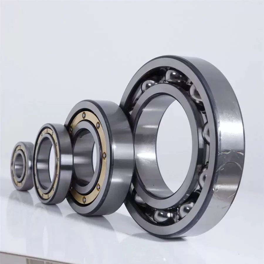
bearing
Ball bearings are made with angular contacts that result in an angle between the bearing’s races. While the axial load moves in 1 direction through the bearing, the radial load follows a curved path, tending to separate the races axially. In order to minimize this frictional effect, angular contact bearings are designed with the same contact angle on the inner and outer races. The contact angle must be chosen to match the relative proportions of the axial and radial loads. Generally, a larger contact angle supports a higher axial load, while reducing radial load.
Ball bearings are the most common type of angular contact bearings. Angular contact ball bearings are used in many applications, but their primary purpose is in the spindle of a machine tool. These bearings are suitable for high-speed, precision rotation. Their radial load capacity is proportional to the angular contact angle, so larger contact angles tend to enlarge with speed. Angular contact ball bearings are available in single and double-row configurations.
Angular contact ball bearings are a great choice for applications that involve axial loads and complex shapes. These bearings have raceways on the inner and outer rings and mutual displacement along the axial axis. Their axial load bearing capacity increases as the contact Angle a rises. Angular contact ball bearings can withstand loads up to 5 times their initial weight! For those who are new to bearings, there are many resources online dedicated to the subject.
Despite their complexity, angular contact ball bearings are highly versatile and can be used in a wide range of applications. Their angular contact enables them to withstand moderate radial and thrust loads. Unlike some other bearings, angular contact ball bearings can be positioned in tandem to reduce friction. They also feature a preload mechanism that removes excess play while the bearing is in use.
Angular contact ball bearings are made with different lubricants and cage materials. Standard cages for angular contact ball bearings correspond to Table 1. Some are machined synthetic resins while others are molded polyamide. These cage materials are used to further enhance the bearing’s axial load capacity. Further, angular contact ball bearings can withstand high speeds and radial loads. Compared to radial contact ball bearings, angular contact ball bearings offer the greatest flexibility.

Ball bearings
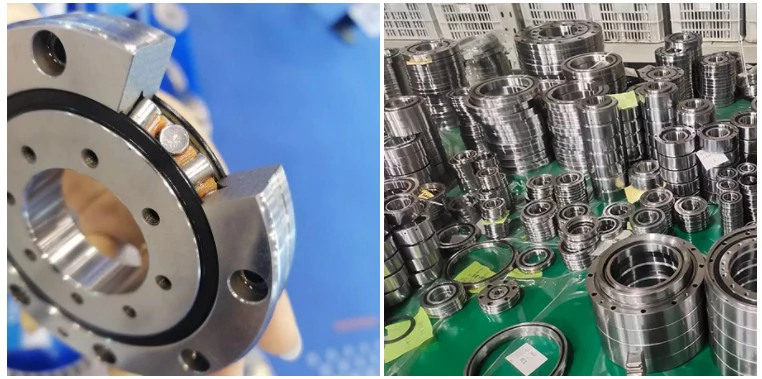
bearing
Ball bearings are circular structures with 2 separate rings. The smaller ring is mounted on a shaft. The inner ring has a groove on the outer diameter that acts as a path for the balls. Both the inner and outer ring surfaces are finished with very high precision and tolerance. The outer ring is the circular structure with the rolling elements. These elements can take many forms. The inner and outer races are generally made of steel or ceramic.
Silicon nitride ceramic balls have good corrosion resistance and lightweight, but are more expensive than aluminum oxide balls. They also exhibit an insulating effect and are self-lubricating. Silicon nitride is also suitable for high-temperature environments. However, this type of material has the disadvantage of wearing out rapidly and is prone to cracking and shattering, as is the case with bearing steel and glass. It’s also less resistant to heat than aluminum oxide, so it’s best to buy aluminum nitride or ceramic ball bearings for applications that are subjected to extremely high temperatures.
Another type of ball bearings is the thrust bearing. It has a special design that accommodates forces in both axial and radial directions. It is also called a bidirectional bearing because its races are side-by-side. Axial ball bearings use a side-by-side design, and axial balls are used when the loads are transmitted through the wheel. However, they have poor axial support and are prone to separating during heavy radial loads.
The basic idea behind ball bearings is to reduce friction. By reducing friction, you’ll be able to transfer more energy, have less erosion, and improve the life of your machine. With today’s advances in technology, ball bearings can perform better than ever before. From iron to steel to plastics, the materials used in bearings have improved dramatically. Bearings may also incorporate an electromagnetic field. So, it’s best to select the right 1 for your machine.
The life expectancy of ball bearings depends on many factors, including the operating speed, lubrication, and temperature. A single million-rpm ball bearing can handle between 1 and 5 million rotations. As long as its surface contact area is as small as possible, it’s likely to be serviceable for at least 1 million rotations. However, the average lifespan of ball bearings depends on the application and operating conditions. Fortunately, most bearings can handle a million or more rotations before they start showing signs of fatigue.

Sliding-contact bearings
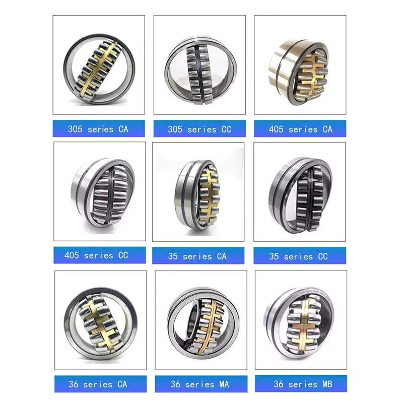
bearing
The basic principle behind sliding-contact bearings is that 2 surfaces move in contact with 1 another. This type of bearing works best in situations where the surfaces are made of dissimilar materials. For instance, a steel shaft shouldn’t run in a bronze-lined bore, or vice versa. Instead, 1 element should be harder than the other, since wear would concentrate in that area. In addition, abrasive particles tend to force themselves into the softer surface, causing a groove to wear in that part.
Sliding-contact bearings have low coefficients of friction and are commonly used in low-speed applications. Unlike ball and roller bearings, sliding contact bearings have to be lubricated on both sides of the contacting surfaces to minimize wear and tear. Sliding-contact bearings generally are made of ceramics, brass, and polymers. Because of their lower friction, they are less accurate than rolling-element bearings.
Sliding-contact bearings are also known as plain or sleeve bearings. They have a sliding motion between their 2 surfaces, which is reduced by lubrication. This type of bearing is often used in rotary applications and as guide mechanisms. In addition to providing sliding action, sliding-contact bearings are self-lubricating and have high load-carrying capacities. They are typically available in 2 different types: plain bearings and thrust bearings.
Sliding-contact linear bearing systems consist of a moving structure (called the carriage or slide) and the surfaces on which the 2 elements slide. The surfaces on which the bearing and journal move are called rails, ways, or guides. A bore hole is a complex geometry, and a minimum oil film thickness h0 is usually used at the line of centers. It is possible to have a sliding-contact bearing in a pillow block.
Because these bearings are porous, they can absorb 15 to 30% of the lubrication oil. This material is commonly used in automobile and machine tools. Many non-metallic materials are used as bearings. One example is rubber, which offers excellent shock absorbency and embeddability. While rubber has poor strength and thermal conductivity, it is commonly used in deep-well pumps and centrifugal pumps. This material has high impact strength, but is not as rigid as steel.

China wholesaler China OEM Iron Casting Parts for Tractor     with Hot sellingChina wholesaler China OEM Iron Casting Parts for Tractor     with Hot selling

China supplier High Quality Sheet Metal Fabrication Stainless Stee Deep Drawing Parts near me supplier

Product Description

Custom Stainless steel deep drawing metal stamping deep drawn

HangZhou HangZhou Metal Products Co., Ltd. is a full-service stainless steel fabrication manufacturer recognized world-wide as a leading manufacturer of deep drawn stamping, progressive dies manufacturing, and all kinds of deep drawn sheet metal stampings.
We provide complex deep drawn metal stampings up to 23″ in depth of draw. We specialize in manufacturing complicated products, and will produce your small, medium, or large deep drawn stamping with the highest levels of precision and quality.

Established in year 2571 with new generation, born with advanced equipment in custom stainless steel deep drawn stamping industry. Our deep expertise in manufacturing deep drawn die components, along with our innovative tool design and manufacturing, ensures economic and sustainable stainless steel products. Serving a variety of industries for example:

  1. Automotive
  2. Consumer
  3. Industrial
  4. Medical

Deep drawn metal stamping material, mainly stainless steel material refers to:

  1. AISI Stainless steel 430
  2. AISI Stainless steel 201
  3. AISI Stainless steel 304
  4. AISI Stainless steel 316
  5. AISI Stainless steel 316L

Our capabilities:
The biggest depth can be drawn to 600mm (23.62 inches), the biggest stainless steel sheet thickness can be 3mm.

The Deep Drawn Stamping Process, although it can be modified to manufacture particular parts, our deep drawn stamping process typically follows the same 5 steps:

1. Design Review: Our engineers review the part design in detail to ensure it is appropriate for deep drawn stamping. This includes in-depth analysis of component dimensions, materials, draw ratio, and required tolerances.

2. Press Selection: Our engineers determine which machine size and caliber will be best suited for the part dimensions and material.

3. 3D Virtual Prototyping: A prototype of the part is created using virtual software. The prototype is run through numerous operational simulations to catch any design problems before the production process begins.

4. Equipment Setup: Our skilled engineers review the component dimensions and requirements and set up the die and punch.

5. Deep Draw Process: The sheet metal, or metal blank, is placed on the die and secured. The press is then activated to force the punch against the die with up to 400 tons of force. The process is repeated until the component achieves the desired size and shape.

We warmly welcome you to visit our factory, if you have any urgent orders, you may also e-mail us for inquiry, we will get back to you the best price in a quick time. Thank you very much.

J N G J I A N G

FAQ

-Never Rust, Cast With Heart-

Q1: Does your factory manufacture customized products?
A: Absolutely yes, we are a stainless steel fabrication manufacturer to make customized products according to your drawings or samples.

Q2: What about order delivery time?
A: It normally will take 15 days for samples( this time will be shortened if stock is available) and 6~7 weeks for mass production, you will see it in the formal quotation sheet during your RFQ.

Q3: Do you have a minimum order quantity limit?
A: Although we are a manufacturer, the minimum order quantity, for example 1pc sample is available for inspection.

Q4: Which kind of stainless steel material do you usually refer to?
A: We usually use AISI stainless steel 430 grade, AISI stainless steel 201 grade, AISI stainless steel 202 grade, AISI stainless steel 304 grade, AISI stainless steel 316 grade, AISI stainless steel 316L grade etc.

Q5:How to buy stainless steel products?
A: Procedures will be like this, firstly, you may share with us your request or application in details. Secondly. We offer you the best quotation according to your request. We may provide you with samples for inspection if you agree with us on prices. Mass production can be applied if customers approve samples and deposit is made accordingly.

Q6: Can my logo be printed on stainless steel products?
A: Yes. Logo printing can be made for mass production order. Please inform us before our production and confirm the design according to our samples.

Q7: Does the product have a warranty?
A: Yes, we offer a 2-5 year warranty according to different products.

Q8: How to deal with any defects?
A: First of all, our products are produced under strict quality control system, and unqualified rate will not exceed 0.2%. Second, in case any defects products happen, we definitely will repair and resend them to you, or both of us will discuss the best solutions to reduce lost in minimum according to actual situation. Thank you very much.

How to Compare Different Types of Spur Gears

When comparing different types of spur gears, there are several important considerations to take into account. The main considerations include the following: Common applications, Pitch diameter, and Addendum circle. Here we will look at each of these factors in more detail. This article will help you understand what each type of spur gear can do for you. Whether you’re looking to power an electric motor or a construction machine, the right gear for the job will make the job easier and save you money in the long run.
Gear

Common applications

Among its many applications, a spur gear is widely used in airplanes, trains, and bicycles. It is also used in ball mills and crushers. Its high speed-low torque capabilities make it ideal for a variety of applications, including industrial machines. The following are some of the common uses for spur gears. Listed below are some of the most common types. While spur gears are generally quiet, they do have their limitations.
A spur gear transmission can be external or auxiliary. These units are supported by front and rear casings. They transmit drive to the accessory units, which in turn move the machine. The drive speed is typically between 5000 and 6000 rpm or 20,000 rpm for centrifugal breathers. For this reason, spur gears are typically used in large machinery. To learn more about spur gears, watch the following video.
The pitch diameter and diametral pitch of spur gears are important parameters. A diametral pitch, or ratio of teeth to pitch diameter, is important in determining the center distance between 2 spur gears. The center distance between 2 spur gears is calculated by adding the radius of each pitch circle. The addendum, or tooth profile, is the height by which a tooth projects above the pitch circle. Besides pitch, the center distance between 2 spur gears is measured in terms of the distance between their centers.
Another important feature of a spur gear is its low speed capability. It can produce great power even at low speeds. However, if noise control is not a priority, a helical gear is preferable. Helical gears, on the other hand, have teeth arranged in the opposite direction of the axis, making them quieter. However, when considering the noise level, a helical gear will work better in low-speed situations.

Construction

The construction of spur gear begins with the cutting of the gear blank. The gear blank is made of a pie-shaped billet and can vary in size, shape, and weight. The cutting process requires the use of dies to create the correct gear geometry. The gear blank is then fed slowly into the screw machine until it has the desired shape and size. A steel gear blank, called a spur gear billet, is used in the manufacturing process.
A spur gear consists of 2 parts: a centre bore and a pilot hole. The addendum is the circle that runs along the outermost points of a spur gear’s teeth. The root diameter is the diameter at the base of the tooth space. The plane tangent to the pitch surface is called the pressure angle. The total diameter of a spur gear is equal to the addendum plus the dedendum.
The pitch circle is a circle formed by a series of teeth and a diametrical division of each tooth. The pitch circle defines the distance between 2 meshed gears. The center distance is the distance between the gears. The pitch circle diameter is a crucial factor in determining center distances between 2 mating spur gears. The center distance is calculated by adding the radius of each gear’s pitch circle. The dedendum is the height of a tooth above the pitch circle.
Other considerations in the design process include the material used for construction, surface treatments, and number of teeth. In some cases, a standard off-the-shelf gear is the most appropriate choice. It will meet your application needs and be a cheaper alternative. The gear will not last for long if it is not lubricated properly. There are a number of different ways to lubricate a spur gear, including hydrodynamic journal bearings and self-contained gears.
Gear

Addendum circle

The pitch diameter and addendum circle are 2 important dimensions of a spur gear. These diameters are the overall diameter of the gear and the pitch circle is the circle centered around the root of the gear’s tooth spaces. The addendum factor is a function of the pitch circle and the addendum value, which is the radial distance between the top of the gear tooth and the pitch circle of the mating gear.
The pitch surface is the right-hand side of the pitch circle, while the root circle defines the space between the 2 gear tooth sides. The dedendum is the distance between the top of the gear tooth and the pitch circle, and the pitch diameter and addendum circle are the 2 radial distances between these 2 circles. The difference between the pitch surface and the addendum circle is known as the clearance.
The number of teeth in the spur gear must not be less than 16 when the pressure angle is 20 degrees. However, a gear with 16 teeth can still be used if its strength and contact ratio are within design limits. In addition, undercutting can be prevented by profile shifting and addendum modification. However, it is also possible to reduce the addendum length through the use of a positive correction. However, it is important to note that undercutting can happen in spur gears with a negative addendum circle.
Another important aspect of a spur gear is its meshing. Because of this, a standard spur gear will have a meshing reference circle called a Pitch Circle. The center distance, on the other hand, is the distance between the center shafts of the 2 gears. It is important to understand the basic terminology involved with the gear system before beginning a calculation. Despite this, it is essential to remember that it is possible to make a spur gear mesh using the same reference circle.

Pitch diameter

To determine the pitch diameter of a spur gear, the type of drive, the type of driver, and the type of driven machine should be specified. The proposed diametral pitch value is also defined. The smaller the pitch diameter, the less contact stress on the pinion and the longer the service life. Spur gears are made using simpler processes than other types of gears. The pitch diameter of a spur gear is important because it determines its pressure angle, the working depth, and the whole depth.
The ratio of the pitch diameter and the number of teeth is called the DIAMETRAL PITCH. The teeth are measured in the axial plane. The FILLET RADIUS is the curve that forms at the base of the gear tooth. The FULL DEPTH TEETH are the ones with the working depth equal to 2.000 divided by the normal diametral pitch. The hub diameter is the outside diameter of the hub. The hub projection is the distance the hub extends beyond the gear face.
A metric spur gear is typically specified with a Diametral Pitch. This is the number of teeth per inch of the pitch circle diameter. It is generally measured in inverse inches. The normal plane intersects the tooth surface at the point where the pitch is specified. In a helical gear, this line is perpendicular to the pitch cylinder. In addition, the pitch cylinder is normally normal to the helix on the outside.
The pitch diameter of a spur gear is typically specified in millimeters or inches. A keyway is a machined groove on the shaft that fits the key into the shaft’s keyway. In the normal plane, the pitch is specified in inches. Involute pitch, or diametral pitch, is the ratio of teeth per inch of diameter. While this may seem complicated, it’s an important measurement to understand the pitch of a spur gear.
gear

Material

The main advantage of a spur gear is its ability to reduce the bending stress at the tooth no matter the load. A typical spur gear has a face width of 20 mm and will fail when subjected to 3000 N. This is far more than the yield strength of the material. Here is a look at the material properties of a spur gear. Its strength depends on its material properties. To find out what spur gear material best suits your machine, follow the following steps.
The most common material used for spur gears is steel. There are different kinds of steel, including ductile iron and stainless steel. S45C steel is the most common steel and has a 0.45% carbon content. This type of steel is easily obtainable and is used for the production of helical, spur, and worm gears. Its corrosion resistance makes it a popular material for spur gears. Here are some advantages and disadvantages of steel.
A spur gear is made of metal, plastic, or a combination of these materials. The main advantage of metal spur gears is their strength to weight ratio. It is about 1 third lighter than steel and resists corrosion. While aluminum is more expensive than steel and stainless steel, it is also easier to machine. Its design makes it easy to customize for the application. Its versatility allows it to be used in virtually every application. So, if you have a specific need, you can easily find a spur gear that fits your needs.
The design of a spur gear greatly influences its performance. Therefore, it is vital to choose the right material and measure the exact dimensions. Apart from being important for performance, dimensional measurements are also important for quality and reliability. Hence, it is essential for professionals in the industry to be familiar with the terms used to describe the materials and parts of a gear. In addition to these, it is essential to have a good understanding of the material and the dimensional measurements of a gear to ensure that production and purchase orders are accurate.

China supplier High Quality Sheet Metal Fabrication Stainless Stee Deep Drawing Parts     near me supplier China supplier High Quality Sheet Metal Fabrication Stainless Stee Deep Drawing Parts     near me supplier

China Professional Manufacture OEM Brass Auto CNC Machining Parts Aluminum Metal and Plastic Mini CNC Parts with Best Sales

Product Description

Product Description


Product Type CNC turning, stamping ,milling, drilling, grinding, wire EDM cutting etc.
Our Services CNC Machining,Stamping,Die Casting,Silicone And Rubber,Aluminum Extrusion,Mould Making,etc
Material Aluminum,Brass,Stainless Steel,Copper,Plastic,Wood,Silicone,Rubber,Or as per the customers’ requirements
Surface Treatment Anodizing,Sandblasting,Painting,Powder coating,Plating,Silk Printing,Brushing,Polishing,Laser Engraving
Tolerance 0.01~0.05mm, can customize as per request.
Service Project To provide production design, production and technical service, CZPT development and processing, etc
Drawing Format PRO/E, Auto CAD, Solid Works,IGS,UG, CAD/CAM/CAE
Testing Machine Digital Height Gauge, caliper, Coordinate measuring machine, projection machine, roughness tester, hardness tester and so on
Industry used Machinery; heavy duty equipment; electronic device; Auto spare parts; optical telecommunication
Packing Eco-friendly pp bag / EPE Foam /Carton boxes or wooden boxes
As customer’s specific requirements
Trial sample time 7-10 days after confirmation
Delivery time 7-30 days after receive the pre-payments
Payment Terms T/T,Western Union,Paypal

Hot Sales Products


Our Advantages

Company Profile

Packaging & Shipping

FAQ

1.Are you a manufacturer or a trading company?
We are a 3000-square-meter factory located in zHangZhoug, China.

2.How can I get a quote?
Detailed drawings (PDF/STEP/IGS/DWG…) with material, quantity and surface treatment information.

3. Can I get a quote without drawings?
Sure, we appreciate to receive your samples, pictures or drafts with detailed dimensions for accurate quotation.

4.Will my drawings be divulged if you benefit?
No, we pay much attention to protect our customers’ privacy of drawings

4. Can you provide samples before mass production?
Sure, sample fee is needed, will be returned when mass production if possible.

5. How about the lead time?
Generally, 1-2 weeks for samples, 3-4 weeks for mass production.

6. How do you control the quality?
(1) Material inspection–Check the material surface and roughly dimension.
(2) Production first inspection–To ensure the critical dimension in mass production.
(3) Sampling inspection–Check the quality before sending to the warehouse.
(4) Pre-shipment inspection–100% inspected by QC assistants before shipment.

8. What will you do if we receive poor quality parts?
Please kindly send us the pictures, our engineers will find the solutions and remake them for you asap.

Back to homepage>>>

The benefits of rubber bushings and how they work

If you have experienced increased vibration while driving, you know the importance of replacing the control arm bushings. The resulting metal-to-metal contact can cause annoying driving problems and be a threat to your safety. Over time, the control arm bushings begin to wear out, a process that can be exacerbated by harsh driving conditions and environmental factors. Additionally, larger tires that are more susceptible to bushing wear are also prone to increased vibration transfer, especially for vehicles with shorter sidewalls. Additionally, these plus-sized tires, which are designed to fit on larger rims, have a higher risk of transmitting vibrations through the bushings.
bushing

rubber

Rubber bushings are rubber tubes that are glued into the inner or outer curve of a cylindrical metal part. The rubber is made of polyurethane and is usually prestressed to avoid breaking during installation. In some cases, the material is also elastic, so it can slide. These properties make rubber bushings an integral part of a vehicle’s suspension system. Here are some benefits of rubber bushings and how they work.
Rubber bushings are used to isolate and reduce vibration caused by the movement of the 2 pieces of equipment. They are usually placed between 2 pieces of machinery, such as gears or balls. By preventing vibrations, rubber bushings improve machine function and service life. In addition to improving the overall performance of the machine, the rubber bushing reduces noise and protects the operator from injury. The rubber on the shock absorber also acts as a vibration isolator. It suppresses the energy produced when the 2 parts of the machine interact. They allow a small amount of movement but minimize vibration.
Both rubber and polyurethane bushings have their advantages and disadvantages. The former is the cheapest, but not as durable as polyurethane. Compared to polyurethane, rubber bushings are a better choice for daily commutes, especially long commutes. Polyurethane bushings provide better steering control and road feel than rubber, but can be more expensive than the former. So how do you choose between polyurethane and rubber bushings?

Polyurethane

Unlike rubber, polyurethane bushings resist high stress environments and normal cycling. This makes them an excellent choice for performance builds. However, there are some disadvantages to using polyurethane bushings. Read on to learn about the advantages and disadvantages of polyurethane bushings in suspension applications. Also, see if a polyurethane bushing is suitable for your vehicle.
Choosing the right bushing for your needs depends entirely on your budget and application. Softer bushings have the lowest performance but may have the lowest NVH. Polyurethane bushings, on the other hand, may be more articulated, but less articulated. Depending on your needs, you can choose a combination of features and tradeoffs. While these are good options for everyday use, for racing and hardcore handling applications, a softer option may be a better choice.
The initial hardness of the polyurethane bushing is higher than that of the rubber bushing. The difference between the 2 materials is determined by durometer testing. Polyurethane has a higher hardness than rubber because it does not react to load in the same way. The harder the rubber, the less elastic, and the higher the tear. This makes it an excellent choice for bushings in a variety of applications.

hard

Solid bushings replace the standard bushings on the subframe, eliminating axle clutter. New bushings raise the subframe by 0.59″ (15mm), correcting the roll center. Plus, they don’t create cabin noise. So you can install these bushings even when your vehicle is lowered. But you should consider some facts when installing solid casing. Read on to learn more about these casings.
The stiffest bushing material currently available is solid aluminum. This material hardly absorbs vibrations, but it is not recommended for everyday use. Its stiffness makes it ideal for rail vehicles. The aluminum housing is prone to wear and tear and may not be suitable for street use. However, the solid aluminum bushings provide the stiffest feel and chassis feedback. However, if you want the best performance in everyday driving, you should choose a polyurethane bushing. They have lower friction properties and eliminate binding.
Sturdy subframe bushings will provide more driver feedback. Additionally, it will strengthen the rear body, eliminating any movement caused by the subframe. You can see this structural integration on the M3 and M4 models. The benefits of solid subframe bushings are numerous. They will improve rear-end handling without compromising drivability. So if you plan to install a solid subframe bushing, be sure to choose a solid bushing.
bushing

Capacitor classification

In the circuit, there is a high electric field on both sides of the capacitor grading bushing. This is due to their capacitor cores. The dielectric properties of the primary insulating layer have a great influence on the electric field distribution within the bushing. This article discusses the advantages and disadvantages of capacitor grade bushings. This article discusses the advantages and disadvantages of grading bushings for capacitors in DC power systems.
One disadvantage of capacitor grading bushings is that they are not suitable for higher voltages. Capacitor grading bushings are prone to serious heating problems. This may reduce their long-term reliability. The main disadvantage of capacitor grading bushings is that they increase the radial thermal gradient of the main insulation. This can lead to dielectric breakdown.
Capacitor grading bushing adopts cylindrical structure, which can suppress the influence of temperature on electric field distribution. This reduces the coefficient of inhomogeneity of the electric field in the confinement layer. Capacitor grading bushings have a uniform electric field distribution across their primary insulation. Capacitive graded bushings are also more reliable than nonlinear bushings.
Electric field variation is the most important cause of failure. The electrode extension layer can be patterned to control the electric field to avoid flashover or partial discharge of the primary insulating material. This design can be incorporated into capacitor grading bushings to provide better electric fields in high voltage applications. This type of bushing is suitable for a wide range of applications. This article discusses the advantages and disadvantages of capacitor grade bushings.

Metal

When choosing between plastic and metal sleeves, it is important to choose a product that can handle the required load. Plastic bushings tend to deteriorate and often crack under heavy loads, reducing their mechanical strength and service life. Metal bushings, on the other hand, conduct heat more efficiently, preventing any damage to the mating surfaces. Plastic bushings can also be made with lubricating fillers added to a resin matrix.
Plastic bushings have many advantages over metal bushings, including being cheap and versatile. Plastic bushings are now used in many industries because they are inexpensive and quick to install. These plastic products are also self-lubricating and require less maintenance than metals. They are often used in applications where maintenance costs are high or parts are difficult to access. Also, if they are prone to wear and tear, they are easy to replace.
Metal bushings can be made of PTFE, plastic or bronze and are self-lubricating. Graphite plugs are also available for some metal bushings. Their high load capacity and excellent fatigue resistance make them a popular choice for automotive applications. The bi-metallic sintered bronze layer in these products provides excellent load-carrying capacity and good friction properties. The steel backing also helps reduce processing time and avoids the need for additional pre-lubrication.
bushing

plastic

A plastic bushing is a small ball of material that is screwed onto a nut or locknut on a mechanical assembly. Plastic bushings are very durable and have a low coefficient of friction, making them a better choice for durable parts. Since they do not require lubrication, they last longer and cost less than their metal counterparts. Unlike metal bushings, plastic bushings also don’t scratch or attract dirt.
One type of acetal sleeve is called SF-2. It is made of metal alloy, cold rolled steel and bronze spherical powder. A small amount of surface plastic penetrated into the voids of the copper spherical powder. Plastic bushings are available in a variety of colors, depending on the intended application. SF-2 is available in black or grey RAL 7040. Its d1 diameter is sufficient for most applications.
Another acetal sleeve is UHMW-PE. This material is used in the production of bearings and in low load applications. This material can withstand pressures from 500 to 800 PSI and is widely available. It is also self-lubricating and readily available. Due to its high resistance to temperature and chemical agents, it is an excellent choice for low-load industrial applications. If you’re in the market for an alternative to nylon, consider acetal.
Positional tolerances in many automotive components can cause misalignment. Misaligned plastic bushings can negatively impact the driver’s experience. For example, the cross tubes used to mount the seat to the frame are made by a stamping process. The result is a misalignment that can increase torque. Also, the plastic bushing is pushed to 1 side of the shaft. The increased pressure results in higher friction, which ultimately results in a poor driving experience.
v
China Professional Manufacture OEM Brass Auto CNC Machining Parts Aluminum Metal and Plastic Mini CNC Parts     with Best SalesChina Professional Manufacture OEM Brass Auto CNC Machining Parts Aluminum Metal and Plastic Mini CNC Parts     with Best Sales

China Standard ODM High Demand High Precision Machinery Parts CNC Machining Aluminum Motorcycle Spare Part Aluminum CNC Machining Part near me factory

Product Description

Product Description


Product Type CNC turning, stamping ,milling, drilling, grinding, wire EDM cutting etc.
Our Services CNC Machining,Stamping,Die Casting,Silicone And Rubber,Aluminum Extrusion,Mould Making,etc
Material Aluminum,Brass,Stainless Steel,Copper,Plastic,Wood,Silicone,Rubber,Or as per the customers’ requirements
Surface Treatment Anodizing,Sandblasting,Painting,Powder coating,Plating,Silk Printing,Brushing,Polishing,Laser Engraving
Tolerance 0.01~0.05mm, can customize as per request.
Service Project To provide production design, production and technical service, CZPT development and processing, etc
Drawing Format PRO/E, Auto CAD, Solid Works,IGS,UG, CAD/CAM/CAE
Testing Machine Digital Height Gauge, caliper, Coordinate measuring machine, projection machine, roughness tester, hardness tester and so on
Industry used Machinery; heavy duty equipment; electronic device; Auto spare parts; optical telecommunication
Packing Eco-friendly pp bag / EPE Foam /Carton boxes or wooden boxes
As customer’s specific requirements
Trial sample time 7-10 days after confirmation
Delivery time 7-30 days after receive the pre-payments
Payment Terms T/T,Western Union,Paypal

Hot Sales Products


Our Advantages

Company Profile

Packaging & Shipping

FAQ

1.Are you a manufacturer or a trading company?
We are a 3000-square-meter factory located in zHangZhoug, China.

2.How can I get a quote?
Detailed drawings (PDF/STEP/IGS/DWG…) with material, quantity and surface treatment information.

3. Can I get a quote without drawings?
Sure, we appreciate to receive your samples, pictures or drafts with detailed dimensions for accurate quotation.

4.Will my drawings be divulged if you benefit?
No, we pay much attention to protect our customers’ privacy of drawings

4. Can you provide samples before mass production?
Sure, sample fee is needed, will be returned when mass production if possible.

5. How about the lead time?
Generally, 1-2 weeks for samples, 3-4 weeks for mass production.

6. How do you control the quality?
(1) Material inspection–Check the material surface and roughly dimension.
(2) Production first inspection–To ensure the critical dimension in mass production.
(3) Sampling inspection–Check the quality before sending to the warehouse.
(4) Pre-shipment inspection–100% inspected by QC assistants before shipment.

8. What will you do if we receive poor quality parts?
Please kindly send us the pictures, our engineers will find the solutions and remake them for you asap.

Back to homepage>>>

Worm Shafts and Gearboxes

If you have a gearbox, you may be wondering what the best Worm Shaft is for your application. There are several things to consider, including the Concave shape, Number of threads, and Lubrication. This article will explain each factor and help you choose the right Worm Shaft for your gearbox. There are many options available on the market, so don’t hesitate to shop around. If you are new to the world of gearboxes, read on to learn more about this popular type of gearbox.
worm shaft

Concave shape

The geometry of a worm gear varies considerably depending on its manufacturer and its intended use. Early worms had a basic profile that resembled a screw thread and could be chased on a lathe. Later, tools with a straight sided g-angle were developed to produce threads that were parallel to the worm’s axis. Grinding was also developed to improve the finish of worm threads and minimize distortions that occur with hardening.
To select a worm with the proper geometry, the diameter of the worm gear must be in the same unit as the worm’s shaft. Once the basic profile of the worm gear is determined, the worm gear teeth can be specified. The calculation also involves an angle for the worm shaft to prevent it from overheating. The angle of the worm shaft should be as close to the vertical axis as possible.
Double-enveloping worm gears, on the other hand, do not have a throat around the worm. They are helical gears with a straight worm shaft. Since the teeth of the worm are in contact with each other, they produce significant friction. Unlike double-enveloping worm gears, non-throated worm gears are more compact and can handle smaller loads. They are also easy to manufacture.
The worm gears of different manufacturers offer many advantages. For instance, worm gears are 1 of the most efficient ways to increase torque, while lower-quality materials like bronze are difficult to lubricate. Worm gears also have a low failure rate because they allow for considerable leeway in the design process. Despite the differences between the 2 standards, the overall performance of a worm gear system is the same.
The cone-shaped worm is another type. This is a technological scheme that combines a straight worm shaft with a concave arc. The concave arc is also a useful utility model. Worms with this shape have more than 3 contacts at the same time, which means they can reduce a large diameter without excessive wear. It is also a relatively low-cost model.
worm shaft

Thread pattern

A good worm gear requires a perfect thread pattern. There are a few key parameters that determine how good a thread pattern is. Firstly, the threading pattern must be ACME-threaded. If this is not possible, the thread must be made with straight sides. Then, the linear pitch of the “worm” must be the same as the circular pitch of the corresponding worm wheel. In simple terms, this means the pitch of the “worm” is the same as the circular pitch of the worm wheel. A quick-change gearbox is usually used with this type of worm gear. Alternatively, lead-screw change gears are used instead of a quick-change gear box. The pitch of a worm gear equals the helix angle of a screw.
A worm gear’s axial pitch must match the circular pitch of a gear with a higher axial pitch. The circular pitch is the distance between the points of teeth on the worm, while the axial pitch is the distance between the worm’s teeth. Another factor is the worm’s lead angle. The angle between the pitch cylinder and worm shaft is called its lead angle, and the higher the lead angle, the greater the efficiency of a gear.
Worm gear tooth geometry varies depending on the manufacturer and intended use. In early worms, threading resembled the thread on a screw, and was easily chased using a lathe. Later, grinding improved worm thread finishes and minimized distortions from hardening. As a result, today, most worm gears have a thread pattern corresponding to their size. When selecting a worm gear, make sure to check for the number of threads before purchasing it.
A worm gear’s threading is crucial in its operation. Worm teeth are typically cylindrical, and are arranged in a pattern similar to screw or nut threads. Worm teeth are often formed on an axis of perpendicular compared to their parallel counterparts. Because of this, they have greater torque than their spur gear counterparts. Moreover, the gearing has a low output speed and high torque.

Number of threads

Different types of worm gears use different numbers of threads on their planetary gears. A single threaded worm gear should not be used with a double-threaded worm. A single-threaded worm gear should be used with a single-threaded worm. Single-threaded worms are more effective for speed reduction than double-threaded ones.
The number of threads on a worm’s shaft is a ratio that compares the pitch diameter and number of teeth. In general, worms have 1,2,4 threads, but some have three, five, or six. Counting thread starts can help you determine the number of threads on a worm. A single-threaded worm has fewer threads than a multiple-threaded worm, but a multi-threaded worm will have more threads than a mono-threaded planetary gear.
To measure the number of threads on a worm shaft, a small fixture with 2 ground faces is used. The worm must be removed from its housing so that the finished thread area can be inspected. After identifying the number of threads, simple measurements of the worm’s outside diameter and thread depth are taken. Once the worm has been accounted for, a cast of the tooth space is made using epoxy material. The casting is moulded between the 2 tooth flanks. The V-block fixture rests against the outside diameter of the worm.
The circular pitch of a worm and its axial pitch must match the circular pitch of a larger gear. The axial pitch of a worm is the distance between the points of the teeth on a worm’s pitch diameter. The lead of a thread is the distance a thread travels in 1 revolution. The lead angle is the tangent to the helix of a thread on a cylinder.
The worm gear’s speed transmission ratio is based on the number of threads. A worm gear with a high ratio can be easily reduced in 1 step by using a set of worm gears. However, a multi-thread worm will have more than 2 threads. The worm gear is also more efficient than single-threaded gears. And a worm gear with a high ratio will allow the motor to be used in a variety of applications.
worm shaft

Lubrication

The lubrication of a worm gear is particularly challenging, due to its friction and high sliding contact force. Fortunately, there are several options for lubricants, such as compounded oils. Compounded oils are mineral-based lubricants formulated with 10 percent or more fatty acid, rust and oxidation inhibitors, and other additives. This combination results in improved lubricity, reduced friction, and lower sliding wear.
When choosing a lubricant for a worm shaft, make sure the product’s viscosity is right for the type of gearing used. A low viscosity will make the gearbox difficult to actuate and rotate. Worm gears also undergo a greater sliding motion than rolling motion, so grease must be able to migrate evenly throughout the gearbox. Repeated sliding motions will push the grease away from the contact zone.
Another consideration is the backlash of the gears. Worm gears have high gear ratios, sometimes 300:1. This is important for power applications, but is at the same time inefficient. Worm gears can generate heat during the sliding motion, so a high-quality lubricant is essential. This type of lubricant will reduce heat and ensure optimal performance. The following tips will help you choose the right lubricant for your worm gear.
In low-speed applications, a grease lubricant may be sufficient. In higher-speed applications, it’s best to apply a synthetic lubricant to prevent premature failure and tooth wear. In both cases, lubricant choice depends on the tangential and rotational speed. It is important to follow manufacturer’s guidelines regarding the choice of lubricant. But remember that lubricant choice is not an easy task.

China Standard ODM High Demand High Precision Machinery Parts CNC Machining Aluminum Motorcycle Spare Part Aluminum CNC Machining Part     near me factory China Standard ODM High Demand High Precision Machinery Parts CNC Machining Aluminum Motorcycle Spare Part Aluminum CNC Machining Part     near me factory

China manufacturer Good Cheap Wholesale 5 Axis Precision Automatic Lathe Metal Aluminum Brass Stainless Steel Milling Turning CNC Machining Parts near me manufacturer

Product Description

Product Description


Product Type CNC turning, stamping ,milling, drilling, grinding, wire EDM cutting etc.
Our Services CNC Machining,Stamping,Die Casting,Silicone And Rubber,Aluminum Extrusion,Mould Making,etc
Material Aluminum,Brass,Stainless Steel,Copper,Plastic,Wood,Silicone,Rubber,Or as per the customers’ requirements
Surface Treatment Anodizing,Sandblasting,Painting,Powder coating,Plating,Silk Printing,Brushing,Polishing,Laser Engraving
Tolerance 0.01~0.05mm, can customize as per request.
Service Project To provide production design, production and technical service, CZPT development and processing, etc
Drawing Format PRO/E, Auto CAD, Solid Works,IGS,UG, CAD/CAM/CAE
Testing Machine Digital Height Gauge, caliper, Coordinate measuring machine, projection machine, roughness tester, hardness tester and so on
Industry used Machinery; heavy duty equipment; electronic device; Auto spare parts; optical telecommunication
Packing Eco-friendly pp bag / EPE Foam /Carton boxes or wooden boxes
As customer’s specific requirements
Trial sample time 7-10 days after confirmation
Delivery time 7-30 days after receive the pre-payments
Payment Terms T/T,Western Union,Paypal

Hot Sales Products


Our Advantages

Company Profile

Packaging & Shipping

FAQ

1.Are you a manufacturer or a trading company?
We are a 3000-square-meter factory located in zHangZhoug, China.

2.How can I get a quote?
Detailed drawings (PDF/STEP/IGS/DWG…) with material, quantity and surface treatment information.

3. Can I get a quote without drawings?
Sure, we appreciate to receive your samples, pictures or drafts with detailed dimensions for accurate quotation.

4.Will my drawings be divulged if you benefit?
No, we pay much attention to protect our customers’ privacy of drawings

4. Can you provide samples before mass production?
Sure, sample fee is needed, will be returned when mass production if possible.

5. How about the lead time?
Generally, 1-2 weeks for samples, 3-4 weeks for mass production.

6. How do you control the quality?
(1) Material inspection–Check the material surface and roughly dimension.
(2) Production first inspection–To ensure the critical dimension in mass production.
(3) Sampling inspection–Check the quality before sending to the warehouse.
(4) Pre-shipment inspection–100% inspected by QC assistants before shipment.

8. What will you do if we receive poor quality parts?
Please kindly send us the pictures, our engineers will find the solutions and remake them for you asap.

Back to homepage>>>

Tips For Maintaining Your Tractor Parts

In this article, we’ll cover some important tips for maintaining your tractor parts. Read on to learn about clutches and CZPT fittings. We’ll also discuss what tractor parts need to be repaired and how to ensure your equipment stays up and running for years. Also, we’ll discuss preventative maintenance and how to choose the right tractor parts company. This will ensure you’ll never have to replace your parts if you experience a problem.

agriculturalparts

Maintenance of tractor parts

If you own a tractor, then you know how important it is to maintain it properly. You should service it at least once a year or whenever you notice that the tractor has issues. Typically, these issues will include a struggling engine or battery, reduced power, and oil leaks. During a service, you should make sure that all the fluids are at their proper levels and replace worn parts as needed. Ideally, you should have a maintenance checklist for tractor parts, so you can refer to it whenever you have a problem.

It is also important to grease exposed fittings on your tractor. You can purchase lithium-based grease from automotive parts stores, or you can get universal ones that come in aerosol cans. Always remember to properly torque nuts and bolts before putting them back on. If you fail to do this, the parts may become loose and start vibrating. Ensure that these components are greased properly so they don’t become loose and cause problems later on.

If you are using a tractor outdoors, it is important to maintain the tractor’s batteries. This will help protect it from rust and corrosion, both of which can shorten the life of your battery. You can also use a baking soda solution to clean the battery, as it is safe to use. The battery terminals should be clear of obstructions and be inspected frequently. You should also turn off the tractor’s ignition before working on the battery or disconnected lead-acid batteries.

Regularly replace your tractor’s 12 volt battery. A battery is essential for tractor operation, as without it, the starter/generator will not work. Also, make sure to purchase the correct 1 for your tractor model. You should also check the belts on your tractor. If there is any loose bolt or component, you should replace it. Also, make sure to remove any straps or chains that are holding the battery. After replacing the belts, store the tractor’s battery in an area with good climate control. A battery maintainer can be purchased at any auto parts store.

agriculturalparts

Types of tractor clutches

Different types of tractor clutches perform different tasks. For example, single-plate clutches can disengage a tractor’s PTO when the engine is off. On the other hand, sequential clutches can disengage both the wheel drive clutch and the PTO clutch. These types of tractor clutches are common in tractors that have between 15 and 100 horsepower. This article will discuss the differences between these clutches and their functions.

Single-plate clutches are the most common type of tractor clutch. They transfer torque by friction between a clutch plate and the engine’s input shaft. A single-plate clutch has a single plate that is mounted on the clutch shaft. A single-plate clutch has a conical friction surface on each side. When the clutch pedal is pressed, the male cone slides into contact with the female cone. When the clutch pedal is released, the male cone slides away from the engine shaft.

Another type of tractor clutch is the diaphragm clutch. These use less rigid springs to transmit power to the tractor’s wheels. Diaphragm clutches are the same as conventional clutches, except that the lever does not apply pressure to the pressure plate. Both clutches are important to tractor performance and safety. They help farmers make quick turns and help move tractors. Tractors’ diaphragm clutches have inspired many video games.

Modern tractors offer many different types of drivetrains. Here, we compare the advantages of each type. The original drive system relied primarily on the clutch to shift gears and change range. Additionally, it relies on a clutch to engage/disengage the PTO drive. A partial depression stops all drives, while a full depression only stops the transmission. In contrast, modern tractors have independent PTO drives that are independent of the gearbox.

CZPT Accessories

CZPT accessories are available for many tractor parts. These are typically used where grease is required, such as ball joints and universal joints. They are also common on hard surfaces that slide on, such as on a wheelbarrow. You can find them in many places, including on old tractors. To properly lubricate these parts, you should use an electric or cordless grease gun. Both are more expensive than the $10 mini pistol grips, but they help reduce hand fatigue and make maintenance easier.

If you cannot find a CZPT fitting, try a grease fitting tool or fitting activator. These are used to loosen stuck bearings. The tool works by filling it with grease or diesel and hitting it with a hammer to release it. However, investing in a regenerator of the right quality – cheap will do little to help. You can also purchase replacement CZPT accessories in various sizes to replace damaged accessories.

If not cleaned properly, grease can damage moving parts. The rag will help you remove oil from your nipples. Excessive lubrication can cause rust. In addition to damaging moving parts, grease attracts dust, sand and grime. Therefore, it is important to keep CZPT fittings clean and free of grease. If you can’t clean them properly, you can use a grease gun to apply it to the CZPT accessories.

A grease gun can also be a handy tool on your farm. When you need to lubricate tractor parts, grease accessories can help you do just that. If you don’t have a grease gun, consider buying a CZPT with a grease gun. It can make your life easier and keep your parts running smoothly. You can also save a lot of time and money by lubricating parts.

agriculturalparts

Preventive Maintenance

Preventive maintenance of tractor components is critical to maintaining efficiency. Regular tractor maintenance reduces unplanned downtime, increases efficiency and minimizes repair costs. As a tractor owner, it is important to understand and follow the manufacturer’s recommended maintenance procedures for various parts. Read the owner’s manual for the most common problems that can affect your tractor. Preventive maintenance can prevent unexpected costs during the workday or in the field.

A preventative maintenance program should include operator training. Operators must know how to perform routine maintenance tasks and how to complete them properly without fail. Operator training can include a review of the operator’s manual, demonstrations of system controls, and testing of equipment and parts. Operator training can also include creating checklists of minor maintenance tasks to help operators maintain machines properly. This can also reduce the need for emergency repairs or rushed parts shipments.

Proper lubrication and regular inspection of tractor parts are essential to keep your tractor in good condition. Lubrication will keep internal parts from rust and other debris from causing damage. Additionally, tractor owners should regularly change their oil and change oil filters. This will help protect your engine and reduce friction. You can also visit your local dealer for checkups. Finally, clean the air filters, as dust and other particles in the air can cause serious damage to your tractor.

If you live in a cold climate, preventative maintenance on tractor parts is vital to keeping your tractor in peak condition for the winter months. Winter-grade fuel and oil are essential for keeping your tractor running smoothly and efficiently during the cold season. Remember to follow your owner’s manual when it comes to fuel, as fuel that is not appropriate for your climate can clog the filter and cause a breakdown. By following these guidelines, you can ensure that your tractor runs optimally all winter long.

China manufacturer Good Cheap Wholesale 5 Axis Precision Automatic Lathe Metal Aluminum Brass Stainless Steel Milling Turning CNC Machining Parts     near me manufacturer China manufacturer Good Cheap Wholesale 5 Axis Precision Automatic Lathe Metal Aluminum Brass Stainless Steel Milling Turning CNC Machining Parts     near me manufacturer

China Custom Factory Wholesale Stainless Steel Brass Aluminum Parts Precision CNC Machining Parts near me shop

Product Description

Product Description


Product Type CNC turning, stamping ,milling, drilling, grinding, wire EDM cutting etc.
Our Services CNC Machining,Stamping,Die Casting,Silicone And Rubber,Aluminum Extrusion,Mould Making,etc
Material Aluminum,Brass,Stainless Steel,Copper,Plastic,Wood,Silicone,Rubber,Or as per the customers’ requirements
Surface Treatment Anodizing,Sandblasting,Painting,Powder coating,Plating,Silk Printing,Brushing,Polishing,Laser Engraving
Tolerance 0.01~0.05mm, can customize as per request.
Service Project To provide production design, production and technical service, CZPT development and processing, etc
Drawing Format PRO/E, Auto CAD, Solid Works,IGS,UG, CAD/CAM/CAE
Testing Machine Digital Height Gauge, caliper, Coordinate measuring machine, projection machine, roughness tester, hardness tester and so on
Industry used Machinery; heavy duty equipment; electronic device; Auto spare parts; optical telecommunication
Packing Eco-friendly pp bag / EPE Foam /Carton boxes or wooden boxes
As customer’s specific requirements
Trial sample time 7-10 days after confirmation
Delivery time 7-30 days after receive the pre-payments
Payment Terms T/T,Western Union,Paypal

Hot Sales Products


Our Advantages

Company Profile

Packaging & Shipping

FAQ

1.Are you a manufacturer or a trading company?
We are a 3000-square-meter factory located in zHangZhoug, China.

2.How can I get a quote?
Detailed drawings (PDF/STEP/IGS/DWG…) with material, quantity and surface treatment information.

3. Can I get a quote without drawings?
Sure, we appreciate to receive your samples, pictures or drafts with detailed dimensions for accurate quotation.

4.Will my drawings be divulged if you benefit?
No, we pay much attention to protect our customers’ privacy of drawings

4. Can you provide samples before mass production?
Sure, sample fee is needed, will be returned when mass production if possible.

5. How about the lead time?
Generally, 1-2 weeks for samples, 3-4 weeks for mass production.

6. How do you control the quality?
(1) Material inspection–Check the material surface and roughly dimension.
(2) Production first inspection–To ensure the critical dimension in mass production.
(3) Sampling inspection–Check the quality before sending to the warehouse.
(4) Pre-shipment inspection–100% inspected by QC assistants before shipment.

8. What will you do if we receive poor quality parts?
Please kindly send us the pictures, our engineers will find the solutions and remake them for you asap.

Back to homepage>>>

Types of Ball Bearings

There are many types of Ball Bearings available on the market, but which 1 is best for your application? Here, we will discuss the differences between Angular contact, Single-row, High-carbon steel, and Ceramic ball bearings. These types of bearings also feature races, or a groove in the center of each. These races are important in keeping the balls contained within the cylinder. They also provide a groove-baed pathway.
bearing

Ceramic

The ceramic ball used in ball bearings has many advantages. It is lightweight, operates at lower temperatures, has reduced skidding, and is resistant to electrolysis. The ball also exhibits longer fatigue life. All of these factors make the ceramic ball a good choice for many applications. But, how do you know if a ceramic ball bearing is right for your application? Read on to discover why ceramic ball bearings are a better choice than steel or stainless steel ones.
The ceramic balls are 40% more dense than steel. This means less centrifugal force is generated on the bearing, which suppresses heat generation. Because of this reduced friction, ceramic bearings are more efficient at transferring energy. Compared to steel bearings, ceramic balls have longer life spans. Nonetheless, these ceramic balls aren’t as strong as steel. Therefore, it is important to understand the limitations of the ceramic ball bearing before buying one.
The ceramic materials used for ball bearings are resistant to micro-welding. Metals undergo this process when imperfections in the surfaces interact. Eventually, this results in a brittle ball that reduces the life of a bearing. Unlike metals, ceramic materials have a stable behavior at high temperatures and exhibit less thermal expansion. This means that they can be used for applications where lubrication isn’t an option.
While steel balls can easily absorb contaminants and foreign particles, the ceramic ball is insensitive to this, and doesn’t require lubrication. This means they’re not susceptible to corrosion and other common problems. These are just a few reasons why ceramics are a better choice. This technology has a wide range of uses. It’s easy to see why it is so popular. If you’re looking for a new bearing for your application, be sure to contact an AST Applications Engineer. They can analyze your operating conditions and potential failure modes.

Angular contact

An Angular Contact Ball Bearing (also known as an angular-contact bearing) has an axial component that is generated when radial loads are applied. They are generally used in pairs, triplex sets, or quadruplex sets. These bearings are also available with Super Finished Raceways to reduce noise and improve lubricant distribution. Angular contact ball bearings have various design units, such as bore size, outer diameter, and outer ring width.
A single-row angular contact bearing has a radial contact angle that is equal to the angular distance between the 2 rings. Double-row angular bearings are designed for two-way thrust capability. These types of bearings can be purchased at Grainger and other online retailers. A typical angular contact bearing will last up to a million revolutions. They are often used in industrial angular contact bearings.
Single-row angular contact ball bearings feature a set contact angle. These bearings can support radial and axial loads, but they can’t withstand high speeds. Single-row angular contact ball bearings may also have 1 or 2 shoulders relieved. Thrust load is a pressure placed on the bearing when it is installed in an assembly, and it is used to create an angle between the races.
Angular contact ball bearings come in single and double-row configurations. They differ in the axial load they can carry and the type of lubrication they use. Angular contact ball bearings are ideal for high-speed applications and can accommodate both radial and axial loads. The type of contact and lubrication used in angular-contact ball bearings depends on the intended use for the bearing.
bearing

High-carbon steel

Carbon steel is a low-alloy and high-carbon steel used in bearings. This material provides superior strength and fatigue properties for ball and roller bearings. Its mechanical properties are ideal for applications where the temperature is less than 400 degrees Fahrenheit. High-carbon steel is also used to make bearing components for chrome steel bearings. These types of steels are softer than chrome steel but provide superior durability in applications where the material is exposed to severe conditions.
Hardened carbon steel balls with an AISI 1015 hardness index are used in a variety of automotive, commercial, and semi-precision applications. In addition to automotive applications, they are also used in slides, trolleys, and conveyors. AISI 1015 carbon steel balls are used in bearings. They can be purchased in a variety of weights and diameters. Carbon steel balls can also be purchased in nickel-plated or uncoated varieties for decorative purposes.
In order to determine whether a ball bearing is made of high-carbon steel, the material must be tested for its hardness. An ordinary pocket magnet will work well, but an ordinary rare earth magnet isn’t powerful enough to measure the hardness. If it attracts the magnet strongly, the metal is steel, while a weak magnet indicates a non-ferrous material. A hardness test requires a special microhardness test.
A lower-carbon steel is another option. Some miniature bearing manufacturers use a material with less carbon than AISI 440C. This material is also known as KS440 or X65Cr13. After being heat-treated, it develops smaller carbides, resulting in superior low-noise characteristics and the same corrosion-resistance as 440C. These materials are a less expensive alternative than chrome steel, but they are often less durable than chrome alloy steel.

Single-row

Single-row angular contact ball bearings accommodate axial loads in 1 direction. These are normally adjusted against a second bearing. Unlike other ball bearings, they are non-separable and contain an upper and lower shoulder. Single-row ball bearings are made of Chromium Steel (GCr15) which is heat-treated to achieve high uniform hardness and excellent wear resistance. They are the most commonly used type of bearings in the world.
Because of the angular contact between the radial plane and the raceway, single-row ball bearings transmit radial forces from raceway to raceway. A higher a, the greater the axial load carrying capacity of the bearing. Single-row angular contact ball bearings are ideal for high axial loads. However, they have limited preload capabilities and must be installed in pairs. Hence, they are best used for applications where axial forces must be distributed.
Single-row ball bearings can be pre-lubricated and have steel shields. They are also available with rubber seals or snap rings on the outside edge. They are available with various retainers, including pressed steel cages, plastic shields, and rubber seals. A tapered bore is also available upon request. They are ideal for applications where space is limited. The 6200 series of bearings are especially well suited for electrical motors, dental hand tools, and optical encoders.
Single-row angular contact ball bearings are widely used for axial loads. The outer and inner rings have slightly larger radii than the balls. These bearings can accommodate high speeds and low torque. They can also be supplied with different grease levels. If grease is needed, you can choose a lubricant that has different characteristics depending on the application. They are easy to install and maintain. However, they are not recommended for adjacent mounting.
bearing

Plastic

A plastic ball bearing is a highly versatile component that can be mounted in a variety of components, including wheels, pulleys and housings. The outer ring of a plastic bearing is usually the pulley profile. The inner ring can be made of a shaft or polymer. The integrated design of a plastic ball bearing helps to reduce assembly time and cost. Here are some of the benefits of this type of bearing:
First and foremost, plastic balls are lighter than metal balls. They also have less magnetic properties than steel balls, making them the best option for applications requiring low weight and noise. Glass balls are also lighter than stainless steel balls, making them the ideal metal-free choice. They are also very corrosion-resistant, which makes them a great choice for some applications. In addition to being lightweight, polymer ball bearings are also quiet. And because of their low weight, plastic ball bearings are ideal for applications that require fast speed.
Another advantage of plastic bearings is their ability to withstand high temperatures. This material is also abrasion and corrosion-resistant. It meets FDA and USDA acceptance requirements. Aside from its abrasion-resistant and corrosion-resistant properties, these plastics do not transfer heat. Aside from being extremely durable and flexible, most plastics are also self-lubricating. Common plastics include phenolics, acetals, nylon, and ultra high molecular weight polyethylene. Nonetheless, plastics have limitations, and these materials may be damaged by extreme temperatures or cold flow under heavy loads.
Other advantages of plastic ball bearings include their low density, high hardness and low friction coefficient, and ability to withstand heat and corrosion. Ceramics are also lightweight, non-conductive, and have superior resistance to friction. These products can withstand temperatures up to 1,800 degrees Fahrenheit. If you’re in the market for a plastic ball bearing, it’s important to choose the right type of material. And if you’re looking for a high-quality bearing, look no further.

China Custom Factory Wholesale Stainless Steel Brass Aluminum Parts Precision CNC Machining Parts     near me shop China Custom Factory Wholesale Stainless Steel Brass Aluminum Parts Precision CNC Machining Parts     near me shop

China Hot selling Factory Precision OEM Machined CNC Milling Auto CNC Machining Parts with Hot selling

Product Description

Product Description


Product Type CNC turning, stamping ,milling, drilling, grinding, wire EDM cutting etc.
Our Services CNC Machining,Stamping,Die Casting,Silicone And Rubber,Aluminum Extrusion,Mould Making,etc
Material Aluminum,Brass,Stainless Steel,Copper,Plastic,Wood,Silicone,Rubber,Or as per the customers’ requirements
Surface Treatment Anodizing,Sandblasting,Painting,Powder coating,Plating,Silk Printing,Brushing,Polishing,Laser Engraving
Tolerance 0.01~0.05mm, can customize as per request.
Service Project To provide production design, production and technical service, CZPT development and processing, etc
Drawing Format PRO/E, Auto CAD, Solid Works,IGS,UG, CAD/CAM/CAE
Testing Machine Digital Height Gauge, caliper, Coordinate measuring machine, projection machine, roughness tester, hardness tester and so on
Industry used Machinery; heavy duty equipment; electronic device; Auto spare parts; optical telecommunication
Packing Eco-friendly pp bag / EPE Foam /Carton boxes or wooden boxes
As customer’s specific requirements
Trial sample time 7-10 days after confirmation
Delivery time 7-30 days after receive the pre-payments
Payment Terms T/T,Western Union,Paypal

Hot Sales Products


Our Advantages

Company Profile

Packaging & Shipping

FAQ

1.Are you a manufacturer or a trading company?
We are a 3000-square-meter factory located in zHangZhoug, China.

2.How can I get a quote?
Detailed drawings (PDF/STEP/IGS/DWG…) with material, quantity and surface treatment information.

3. Can I get a quote without drawings?
Sure, we appreciate to receive your samples, pictures or drafts with detailed dimensions for accurate quotation.

4.Will my drawings be divulged if you benefit?
No, we pay much attention to protect our customers’ privacy of drawings

4. Can you provide samples before mass production?
Sure, sample fee is needed, will be returned when mass production if possible.

5. How about the lead time?
Generally, 1-2 weeks for samples, 3-4 weeks for mass production.

6. How do you control the quality?
(1) Material inspection–Check the material surface and roughly dimension.
(2) Production first inspection–To ensure the critical dimension in mass production.
(3) Sampling inspection–Check the quality before sending to the warehouse.
(4) Pre-shipment inspection–100% inspected by QC assistants before shipment.

8. What will you do if we receive poor quality parts?
Please kindly send us the pictures, our engineers will find the solutions and remake them for you asap.

Back to homepage>>>

Analytical Approaches to Estimating Contact Pressures in Spline Couplings

A spline coupling is a type of mechanical connection between 2 rotating shafts. It consists of 2 parts – a coupler and a coupling. Both parts have teeth which engage and transfer loads. However, spline couplings are typically over-dimensioned, which makes them susceptible to fatigue and static behavior. Wear phenomena can also cause the coupling to fail. For this reason, proper spline coupling design is essential for achieving optimum performance.
splineshaft

Modeling a spline coupling

Spline couplings are becoming increasingly popular in the aerospace industry, but they operate in a slightly misaligned state, causing both vibrations and damage to the contact surfaces. To solve this problem, this article offers analytical approaches for estimating the contact pressures in a spline coupling. Specifically, this article compares analytical approaches with pure numerical approaches to demonstrate the benefits of an analytical approach.
To model a spline coupling, first you create the knowledge base for the spline coupling. The knowledge base includes a large number of possible specification values, which are related to each other. If you modify 1 specification, it may lead to a warning for violating another. To make the design valid, you must create a spline coupling model that meets the specified specification values.
After you have modeled the geometry, you must enter the contact pressures of the 2 spline couplings. Then, you need to determine the position of the pitch circle of the spline. In Figure 2, the centre of the male coupling is superposed to that of the female spline. Then, you need to make sure that the alignment meshing distance of the 2 splines is the same.
Once you have the data you need to create a spline coupling model, you can begin by entering the specifications for the interface design. Once you have this data, you need to choose whether to optimize the internal spline or the external spline. You’ll also need to specify the tooth friction coefficient, which is used to determine the stresses in the spline coupling model 20. You should also enter the pilot clearance, which is the clearance between the tip 186 of a tooth 32 on 1 spline and the feature on the mating spline.
After you have entered the desired specifications for the external spline, you can enter the parameters for the internal spline. For example, you can enter the outer diameter limit 154 of the major snap 54 and the minor snap 56 of the internal spline. The values of these parameters are displayed in color-coded boxes on the Spline Inputs and Configuration GUI screen 80. Once the parameters are entered, you’ll be presented with a geometric representation of the spline coupling model 20.

Creating a spline coupling model 20

The spline coupling model 20 is created by a product model software program 10. The software validates the spline coupling model against a knowledge base of configuration-dependent specification constraints and relationships. This report is then input to the ANSYS stress analyzer program. It lists the spline coupling model 20’s geometric configurations and specification values for each feature. The spline coupling model 20 is automatically recreated every time the configuration or performance specifications of the spline coupling model 20 are modified.
The spline coupling model 20 can be configured using the product model software program 10. A user specifies the axial length of the spline stack, which may be zero, or a fixed length. The user also enters a radial mating face 148, if any, and selects a pilot clearance specification value of 14.5 degrees or 30 degrees.
A user can then use the mouse 110 to modify the spline coupling model 20. The spline coupling knowledge base contains a large number of possible specification values and the spline coupling design rule. If the user tries to change a spline coupling model, the model will show a warning about a violation of another specification. In some cases, the modification may invalidate the design.
In the spline coupling model 20, the user enters additional performance requirement specifications. The user chooses the locations where maximum torque is transferred for the internal and external splines 38 and 40. The maximum torque transfer location is determined by the attachment configuration of the hardware to the shafts. Once this is selected, the user can click “Next” to save the model. A preview of the spline coupling model 20 is displayed.
The model 20 is a representation of a spline coupling. The spline specifications are entered in the order and arrangement as specified on the spline coupling model 20 GUI screen. Once the spline coupling specifications are entered, the product model software program 10 will incorporate them into the spline coupling model 20. This is the last step in spline coupling model creation.
splineshaft

Analysing a spline coupling model 20

An analysis of a spline coupling model consists of inputting its configuration and performance specifications. These specifications may be generated from another computer program. The product model software program 10 then uses its internal knowledge base of configuration dependent specification relationships and constraints to create a valid three-dimensional parametric model 20. This model contains information describing the number and types of spline teeth 32, snaps 34, and shoulder 36.
When you are analysing a spline coupling, the software program 10 will include default values for various specifications. The spline coupling model 20 comprises an internal spline 38 and an external spline 40. Each of the splines includes its own set of parameters, such as its depth, width, length, and radii. The external spline 40 will also contain its own set of parameters, such as its orientation.
Upon selecting these parameters, the software program will perform various analyses on the spline coupling model 20. The software program 10 calculates the nominal and maximal tooth bearing stresses and fatigue life of a spline coupling. It will also determine the difference in torsional windup between an internal and an external spline. The output file from the analysis will be a report file containing model configuration and specification data. The output file may also be used by other computer programs for further analysis.
Once these parameters are set, the user enters the design criteria for the spline coupling model 20. In this step, the user specifies the locations of maximum torque transfer for both the external and internal spline 38. The maximum torque transfer location depends on the configuration of the hardware attached to the shafts. The user may enter up to 4 different performance requirement specifications for each spline.
The results of the analysis show that there are 2 phases of spline coupling. The first phase shows a large increase in stress and vibration. The second phase shows a decline in both stress and vibration levels. The third stage shows a constant meshing force between 300N and 320N. This behavior continues for a longer period of time, until the final stage engages with the surface.
splineshaft

Misalignment of a spline coupling

A study aimed to investigate the position of the resultant contact force in a spline coupling engaging teeth under a steady torque and rotating misalignment. The study used numerical methods based on Finite Element Method (FEM) models. It produced numerical results for nominal conditions and parallel offset misalignment. The study considered 2 levels of misalignment – 0.02 mm and 0.08 mm – with different loading levels.
The results showed that the misalignment between the splines and rotors causes a change in the meshing force of the spline-rotor coupling system. Its dynamics is governed by the meshing force of splines. The meshing force of a misaligned spline coupling is related to the rotor-spline coupling system parameters, the transmitting torque, and the dynamic vibration displacement.
Despite the lack of precise measurements, the misalignment of splines is a common problem. This problem is compounded by the fact that splines usually feature backlash. This backlash is the result of the misaligned spline. The authors analyzed several splines, varying pitch diameters, and length/diameter ratios.
A spline coupling is a two-dimensional mechanical system, which has positive backlash. The spline coupling is comprised of a hub and shaft, and has tip-to-root clearances that are larger than the backlash. A form-clearance is sufficient to prevent tip-to-root fillet contact. The torque on the splines is transmitted via friction.
When a spline coupling is misaligned, a torque-biased thrust force is generated. In such a situation, the force can exceed the torque, causing the component to lose its alignment. The two-way transmission of torque and thrust is modeled analytically in the present study. The analytical approach provides solutions that can be integrated into the design process. So, the next time you are faced with a misaligned spline coupling problem, make sure to use an analytical approach!
In this study, the spline coupling is analyzed under nominal conditions without a parallel offset misalignment. The stiffness values obtained are the percentage difference between the nominal pitch diameter and load application diameter. Moreover, the maximum percentage difference in the measured pitch diameter is 1.60% under a torque of 5000 N*m. The other parameter, the pitch angle, is taken into consideration in the calculation.

China Hot selling Factory Precision OEM Machined CNC Milling Auto CNC Machining Parts     with Hot sellingChina Hot selling Factory Precision OEM Machined CNC Milling Auto CNC Machining Parts     with Hot selling

China Good quality Factory Direct Sales Wholesale Aluminum Lathe Machine CNC Machining Part with Hot selling

Product Description

Product Description


Product Type CNC turning, stamping ,milling, drilling, grinding, wire EDM cutting etc.
Our Services CNC Machining,Stamping,Die Casting,Silicone And Rubber,Aluminum Extrusion,Mould Making,etc
Material Aluminum,Brass,Stainless Steel,Copper,Plastic,Wood,Silicone,Rubber,Or as per the customers’ requirements
Surface Treatment Anodizing,Sandblasting,Painting,Powder coating,Plating,Silk Printing,Brushing,Polishing,Laser Engraving
Tolerance 0.01~0.05mm, can customize as per request.
Service Project To provide production design, production and technical service, CZPT development and processing, etc
Drawing Format PRO/E, Auto CAD, Solid Works,IGS,UG, CAD/CAM/CAE
Testing Machine Digital Height Gauge, caliper, Coordinate measuring machine, projection machine, roughness tester, hardness tester and so on
Industry used Machinery; heavy duty equipment; electronic device; Auto spare parts; optical telecommunication
Packing Eco-friendly pp bag / EPE Foam /Carton boxes or wooden boxes
As customer’s specific requirements
Trial sample time 7-10 days after confirmation
Delivery time 7-30 days after receive the pre-payments
Payment Terms T/T,Western Union,Paypal

Hot Sales Products


Our Advantages

Company Profile

Packaging & Shipping

FAQ

1.Are you a manufacturer or a trading company?
We are a 3000-square-meter factory located in zHangZhoug, China.

2.How can I get a quote?
Detailed drawings (PDF/STEP/IGS/DWG…) with material, quantity and surface treatment information.

3. Can I get a quote without drawings?
Sure, we appreciate to receive your samples, pictures or drafts with detailed dimensions for accurate quotation.

4.Will my drawings be divulged if you benefit?
No, we pay much attention to protect our customers’ privacy of drawings

4. Can you provide samples before mass production?
Sure, sample fee is needed, will be returned when mass production if possible.

5. How about the lead time?
Generally, 1-2 weeks for samples, 3-4 weeks for mass production.

6. How do you control the quality?
(1) Material inspection–Check the material surface and roughly dimension.
(2) Production first inspection–To ensure the critical dimension in mass production.
(3) Sampling inspection–Check the quality before sending to the warehouse.
(4) Pre-shipment inspection–100% inspected by QC assistants before shipment.

8. What will you do if we receive poor quality parts?
Please kindly send us the pictures, our engineers will find the solutions and remake them for you asap.

Back to homepage>>>

Screw Shaft Features Explained

When choosing the screw shaft for your application, you should consider the features of the screws: threads, lead, pitch, helix angle, and more. You may be wondering what these features mean and how they affect the screw’s performance. This article explains the differences between these factors. The following are the features that affect the performance of screws and their properties. You can use these to make an informed decision and purchase the right screw. You can learn more about these features by reading the following articles.

Threads

The major diameter of a screw thread is the larger of the 2 extreme diameters. The major diameter of a screw is also known as the outside diameter. This dimension can’t be directly measured, but can be determined by measuring the distance between adjacent sides of the thread. In addition, the mean area of a screw thread is known as the pitch. The diameter of the thread and pitch line are directly proportional to the overall size of the screw.
The threads are classified by the diameter and pitch. The major diameter of a screw shaft has the largest number of threads; the smaller diameter is called the minor diameter. The thread angle, also known as the helix angle, is measured perpendicular to the axis of the screw. The major diameter is the largest part of the screw; the minor diameter is the lower end of the screw. The thread angle is the half distance between the major and minor diameters. The minor diameter is the outer surface of the screw, while the top surface corresponds to the major diameter.
The pitch is measured at the crest of a thread. In other words, a 16-pitch thread has a diameter of 1 sixteenth of the screw shaft’s diameter. The actual diameter is 0.03125 inches. Moreover, a large number of manufacturers use this measurement to determine the thread pitch. The pitch diameter is a critical factor in successful mating of male and female threads. So, when determining the pitch diameter, you need to check the thread pitch plate of a screw.
screwshaft

Lead

In screw shaft applications, a solid, corrosion-resistant material is an important requirement. Lead screws are a robust choice, which ensure shaft direction accuracy. This material is widely used in lathes and measuring instruments. They have black oxide coatings and are suited for environments where rusting is not acceptable. These screws are also relatively inexpensive. Here are some advantages of lead screws. They are highly durable, cost-effective, and offer high reliability.
A lead screw system may have multiple starts, or threads that run parallel to each other. The lead is the distance the nut travels along the shaft during a single revolution. The smaller the lead, the tighter the thread. The lead can also be expressed as the pitch, which is the distance between adjacent thread crests or troughs. A lead screw has a smaller pitch than a nut, and the smaller the lead, the greater its linear speed.
When choosing lead screws, the critical speed is the maximum number of revolutions per minute. This is determined by the minor diameter of the shaft and its length. The critical speed should never be exceeded or the lead will become distorted or cracked. The recommended operational speed is around 80 percent of the evaluated critical speed. Moreover, the lead screw must be properly aligned to avoid excessive vibrations. In addition, the screw pitch must be within the design tolerance of the shaft.

Pitch

The pitch of a screw shaft can be viewed as the distance between the crest of a thread and the surface where the threads meet. In mathematics, the pitch is equivalent to the length of 1 wavelength. The pitch of a screw shaft also relates to the diameter of the threads. In the following, the pitch of a screw is explained. It is important to note that the pitch of a screw is not a metric measurement. In the following, we will define the 2 terms and discuss how they relate to 1 another.
A screw’s pitch is not the same in all countries. The United Kingdom, Canada, and the United States have standardized screw threads according to the UN system. Therefore, there is a need to specify the pitch of a screw shaft when a screw is being manufactured. The standardization of pitch and diameter has also reduced the cost of screw manufacturing. Nevertheless, screw threads are still expensive. The United Kingdom, Canada, and the United States have introduced a system for the calculation of screw pitch.
The pitch of a lead screw is the same as that of a lead screw. The diameter is 0.25 inches and the circumference is 0.79 inches. When calculating the mechanical advantage of a screw, divide the diameter by its pitch. The larger the pitch, the more threads the screw has, increasing its critical speed and stiffness. The pitch of a screw shaft is also proportional to the number of starts in the shaft.

Helix angle

The helix angle of a screw shaft is the angle formed between the circumference of the cylinder and its helix. Both of these angles must be equal to 90 degrees. The larger the lead angle, the smaller the helix angle. Some reference materials refer to angle B as the helix angle. However, the actual angle is derived from calculating the screw geometry. Read on for more information. Listed below are some of the differences between helix angles and lead angles.
High helix screws have a long lead. This length reduces the number of effective turns of the screw. Because of this, fine pitch screws are usually used for small movements. A typical example is a 16-mm x 5-inch screw. Another example of a fine pitch screw is a 12x2mm screw. It is used for small moves. This type of screw has a lower lead angle than a high-helix screw.
A screw’s helix angle refers to the relative angle of the flight of the helix to the plane of the screw axis. While screw helix angles are not often altered from the standard square pitch, they can have an effect on processing. Changing the helix angle is more common in two-stage screws, special mixing screws, and metering screws. When a screw is designed for this function, it should be able to handle the materials it is made of.
screwshaft

Size

The diameter of a screw is its diameter, measured from the head to the shaft. Screw diameters are standardized by the American Society of Mechanical Engineers. The diameters of screws range from 3/50 inches to 16 inches, and more recently, fractions of an inch have been added. However, shaft diameters may vary depending on the job, so it is important to know the right size for the job. The size chart below shows the common sizes for screws.
Screws are generally referred to by their gauge, which is the major diameter. Screws with a major diameter less than a quarter of an inch are usually labeled as #0 to #14 and larger screws are labeled as sizes in fractions of an inch. There are also decimal equivalents of each screw size. These measurements will help you choose the correct size for your project. The screws with the smaller diameters were not tested.
In the previous section, we described the different shaft sizes and their specifications. These screw sizes are usually indicated by fractions of an inch, followed by a number of threads per inch. For example, a ten-inch screw has a shaft size of 2” with a thread pitch of 1/4″, and it has a diameter of 2 inches. This screw is welded to a two-inch Sch. 40 pipe. Alternatively, it can be welded to a 9-inch O.A.L. pipe.
screwshaft

Shape

Screws come in a wide variety of sizes and shapes, from the size of a quarter to the diameter of a U.S. quarter. Screws’ main function is to hold objects together and to translate torque into linear force. The shape of a screw shaft, if it is round, is the primary characteristic used to define its use. The following chart shows how the screw shaft differs from a quarter:
The shape of a screw shaft is determined by 2 features: its major diameter, or distance from the outer edge of the thread on 1 side to the inner smooth surface of the shaft. These are generally 2 to 16 millimeters in diameter. Screw shafts can have either a fully threaded shank or a half-threaded shank, with the latter providing better stability. Regardless of whether the screw shaft is round or domed, it is important to understand the different characteristics of a screw before attempting to install it into a project.
The screw shaft’s diameter is also important to its application. The ball circle diameter refers to the distance between the center of 2 opposite balls in contact with the grooves. The root diameter, on the other hand, refers to the distance between the bottommost grooves of the screw shaft. These are the 2 main measurements that define the screw’s overall size. Pitch and nominal diameter are important measurements for a screw’s performance in a particular application.

Lubrication

In most cases, lubrication of a screw shaft is accomplished with grease. Grease is made up of mineral or synthetic oil, thickening agent, and additives. The thickening agent can be a variety of different substances, including lithium, bentonite, aluminum, and barium complexes. A common classification for lubricating grease is NLGI Grade. While this may not be necessary when specifying the type of grease to use for a particular application, it is a useful qualitative measure.
When selecting a lubricant for a screw shaft, the operating temperature and the speed of the shaft determine the type of oil to use. Too much oil can result in heat buildup, while too little can lead to excessive wear and friction. The proper lubrication of a screw shaft directly affects the temperature rise of a ball screw, and the life of the assembly. To ensure the proper lubrication, follow the guidelines below.
Ideally, a low lubrication level is appropriate for medium-sized feed stuff factories. High lubrication level is appropriate for larger feed stuff factories. However, in low-speed applications, the lubrication level should be sufficiently high to ensure that the screws run freely. This is the only way to reduce friction and ensure the longest life possible. Lubrication of screw shafts is an important consideration for any screw.

China Good quality Factory Direct Sales Wholesale Aluminum Lathe Machine CNC Machining Part     with Hot sellingChina Good quality Factory Direct Sales Wholesale Aluminum Lathe Machine CNC Machining Part     with Hot selling

China OEM Custom Made Aluminium Brass Stainless Steel CNC Machining Parts near me supplier

Product Description

Product Description


Product Type CNC turning, stamping ,milling, drilling, grinding, wire EDM cutting etc.
Our Services CNC Machining,Stamping,Die Casting,Silicone And Rubber,Aluminum Extrusion,Mould Making,etc
Material Aluminum,Brass,Stainless Steel,Copper,Plastic,Wood,Silicone,Rubber,Or as per the customers’ requirements
Surface Treatment Anodizing,Sandblasting,Painting,Powder coating,Plating,Silk Printing,Brushing,Polishing,Laser Engraving
Tolerance 0.01~0.05mm, can customize as per request.
Service Project To provide production design, production and technical service, CZPT development and processing, etc
Drawing Format PRO/E, Auto CAD, Solid Works,IGS,UG, CAD/CAM/CAE
Testing Machine Digital Height Gauge, caliper, Coordinate measuring machine, projection machine, roughness tester, hardness tester and so on
Industry used Machinery; heavy duty equipment; electronic device; Auto spare parts; optical telecommunication
Packing Eco-friendly pp bag / EPE Foam /Carton boxes or wooden boxes
As customer’s specific requirements
Trial sample time 7-10 days after confirmation
Delivery time 7-30 days after receive the pre-payments
Payment Terms T/T,Western Union,Paypal

Hot Sales Products


Our Advantages

Company Profile

Packaging & Shipping

FAQ

1.Are you a manufacturer or a trading company?
We are a 3000-square-meter factory located in zHangZhoug, China.

2.How can I get a quote?
Detailed drawings (PDF/STEP/IGS/DWG…) with material, quantity and surface treatment information.

3. Can I get a quote without drawings?
Sure, we appreciate to receive your samples, pictures or drafts with detailed dimensions for accurate quotation.

4.Will my drawings be divulged if you benefit?
No, we pay much attention to protect our customers’ privacy of drawings

4. Can you provide samples before mass production?
Sure, sample fee is needed, will be returned when mass production if possible.

5. How about the lead time?
Generally, 1-2 weeks for samples, 3-4 weeks for mass production.

6. How do you control the quality?
(1) Material inspection–Check the material surface and roughly dimension.
(2) Production first inspection–To ensure the critical dimension in mass production.
(3) Sampling inspection–Check the quality before sending to the warehouse.
(4) Pre-shipment inspection–100% inspected by QC assistants before shipment.

8. What will you do if we receive poor quality parts?
Please kindly send us the pictures, our engineers will find the solutions and remake them for you asap.

Back to homepage>>>

What Is a Worm Gear Reducer?

If you have never seen a worm gear reducer before, you’re missing out! Learn more about these incredible gears and their applications by reading this article! In addition to worm gear reducers, learn about worms and how they’re made. You’ll also discover what types of machines can benefit from worm gears, such as rock crushers and elevators. The following information will help you understand what a worm gear reducer is and how to find 1 in your area.
worm shaft

Typical worm shaft

A typical worm has 2 shafts, 1 for advancing and 1 for receding, which form the axial pitch of the gear. Usually, there are 8 standard axial pitches, which establish a basic dimension for worm production and inspection. The axial pitch of the worm equals the circular pitch of the gear in the central plane and the master lead cam’s radial pitch. A single set of change gears and 1 master lead cam are used to produce each size of worm.
Worm gear is commonly used to manufacture a worm shaft. It is a reliable and efficient gear reduction system that does not move when the power is removed. Typical worm gears come in standard sizes as well as assisted systems. Manufacturers can be found online. Listed below are some common materials for worm gears. There are also many options for lubrication. The worm gear is typically made from case hardened steel or bronze. Non-metallic materials are also used in light-duty applications.
A self-locking worm gear prevents the worm from moving backwards. Typical worm gears are generally self-locking when the lead angle is less than 11 degrees. However, this feature can be detrimental to systems that require reverse sensitivity. If the lead angle is less than 4 degrees, back-driving is unlikely. However, if fail-safe protection is a prerequisite, back-driving worm gears must have a positive brake to avoid reverse movement.
Worm gears are often used in transmission applications. They are a more efficient way to reduce the speed of a machine compared to conventional gear sets. Their reduced speed is possible thanks to their low ratio and few components. Unlike conventional gear sets, worm gears require less maintenance and lower mechanical failure than a conventional gear set. While they require fewer parts, worm gears are also more durable than conventional gear sets.
There are 2 types of worm tooth forms. Convex and involute helicoids have different types of teeth. The former uses a straight line to intersect the involute worm generating line. The latter, on the other hand, uses a trapezoid based on the central cross section of the root. Both of these tooth forms are used in the production of worms. And they have various variations in pitch diameter.
worm shaft

Types of worms

Worms have several forms of tooth. For convenience in production, a trapezoid-based tooth form is used. Other forms include an involute helicoidal or a convolute worm generating a line. The following is a description of each type. All types are similar, and some may be preferred over others. Listed below are the 3 most common worm shaft types. Each type has its own advantages and disadvantages.
Discrete versus parallel axis: The design of a worm gear determines its ratio of torque. It’s a combination of 2 different metals – 1 for the worm and 1 for the wheel – which helps it absorb shock loads. Construction equipment and off-road vehicles typically require varying torques to maneuver over different terrain. A worm gear system can help them maneuver over uneven terrain without causing excessive wear.
Worm gear units have the highest ratio. The sliding action of the worm shaft results in a high self-locking torque. Depending on the angle of inclination and friction, a worm gear can reach up to 100:1! Worm gears can be made of different materials depending on their inclination and friction angle. Worm gears are also useful for gear reduction applications, such as lubrication or grinding. However, you should consider that heavier gears tend to be harder to reverse than lighter ones.
Metal alloy: Stainless steel, brass, and aluminum bronze are common materials for worm gears. All 3 types have unique advantages. A bronze worm gear is typically composed of a combination of copper, zinc, and tin. A bronze shaft is more corrosive than a brass one, but it is a durable and corrosion-resistant option. Metal alloys: These materials are used for both the worm wheel.
The efficiency of worm gears depends on the assembly conditions and the lubricant. A 30:1 ratio reduces the efficiency to 81:1%. A worm gear is more efficient at higher ratios than an helical gear, but a 30:1 ratio reduces the efficiency to 81%. A helical gear reduces speed while preserving torque to around 15% of the original speed. The difference in efficiency between worm gear and helical gear is about half an hour!

Methods of manufacturing worm shafts

Several methods of manufacturing worm shafts are available in the market. Single-pointed lathe tools or end mills are the most popular methods for manufacturing worms. These tools are capable of producing worms with different pressure angles depending on their diameter, the depth of thread, and the grinding wheel’s diameter. The diagram below shows how different pressure angles influence the profile of worms manufactured using different cutting tools.
The method for making worm shafts involves the process of establishing the proper outer diameter of a common worm shaft blank. This may include considering the number of reduction ratios in a family, the distance between the worm shaft and the gear set center, as well as the torques involved. These processes are also referred to as ‘thread assembly’. Each process can be further refined if the desired axial pitch can be achieved.
The axial pitch of a worm must match the circular pitch of the larger gear. This is called the pitch. The pitch diameter and axial pitch must be equal. Worms can be left-handed or right-handed. The lead, which refers to the distance a point on the thread travels during 1 revolution of the worm, is defined by its angle of tangent to the helix on the pitch of the cylinder.
Worm shafts are commonly manufactured using a worm gear. Worm gears can be used in different applications because they offer fine adjustment and high gear reduction. They can be made in both standard sizes and assisted systems. Worm shaft manufacturers can be found online. Alternatively, you can contact a manufacturer directly to get your worm gears manufactured. The process will take only a few minutes. If you are looking for a manufacturer of worm gears, you can browse a directory.
Worm gears are made with hardened metal. The worm wheel and gear are yellow in color. A compounded oil with rust and oxidation inhibitors is also used to make worm gears. These oils adhere to the shaft walls and make a protective barrier between the surfaces. If the compounded oil is applied correctly, the worm gear will reduce the noise in a motor, resulting in a smoother performance.
worm shaft

applications for worm gear reducers

Worm gears are widely used in power transmission applications, providing a compact, high reduction, low-speed drive. To determine the torque ratio of worm gears, a numerical model was developed that makes use of the equation of displacement compatibility and the influence coefficient method, which provides fast computing. The numerical model also incorporates bending deflections of the gear surfaces and the mating surfaces. It is based on the Boussinesq theory, which calculates local contact deformations.
Worm gears can be designed to be right or left-handed, and the worm can turn either clockwise or counter-clockwise. An internal helical gear requires the same hand to operate both parts. In contrast, an external helical gear must be operated by the opposite hand. The same principle applies to worm gears in other applications. The torque and power transferred can be large, but worm gears are able to cope with large reductions in both directions.
Worm gears are extremely useful in industrial machinery designs. They reduce noise levels, save space, and give machines extra precision and fast-stopping capabilities. Worm gears are also available in compact versions, making them ideal for hoisting applications. This type of gear reducer is used in industrial settings where space is an issue. Its smaller size and less noise makes it ideal for applications that need the machine to stop quickly.
A double-throated worm gear offers the highest load capacity while still remaining compact. The double-throated version features concave teeth on both worm and gear, doubling the contact area between them. Worm gears are also useful for low to moderate-horsepower applications, and their high ratios, high output torque, and significant speed reduction make them a desirable choice for many applications. Worm gears are also quieter than other types of gears, reducing the noise and vibrations that they cause.
Worm gears have numerous advantages over other types of gears. They have high levels of conformity and can be classified as a screw pair within a lower-pair gear family. Worm gears are also known to have a high degree of relative sliding. Worm gears are often made of hardened steel or phosphor-bronze, which provides good surface finish and rigid positioning. Worm gears are lubricated with special lubricants that contain surface-active additives. Worm gear lubrication is a mixed lubrication process and causes mild wear and tear.

China OEM Custom Made Aluminium Brass Stainless Steel CNC Machining Parts     near me supplier China OEM Custom Made Aluminium Brass Stainless Steel CNC Machining Parts     near me supplier

China high quality Aluminum Gun Titanium High Demand CNC Machining Parts with Free Design Custom

Product Description

Product Description


Product Type CNC turning, stamping ,milling, drilling, grinding, wire EDM cutting etc.
Our Services CNC Machining,Stamping,Die Casting,Silicone And Rubber,Aluminum Extrusion,Mould Making,etc
Material Aluminum,Brass,Stainless Steel,Copper,Plastic,Wood,Silicone,Rubber,Or as per the customers’ requirements
Surface Treatment Anodizing,Sandblasting,Painting,Powder coating,Plating,Silk Printing,Brushing,Polishing,Laser Engraving
Tolerance 0.01~0.05mm, can customize as per request.
Service Project To provide production design, production and technical service, CZPT development and processing, etc
Drawing Format PRO/E, Auto CAD, Solid Works,IGS,UG, CAD/CAM/CAE
Testing Machine Digital Height Gauge, caliper, Coordinate measuring machine, projection machine, roughness tester, hardness tester and so on
Industry used Machinery; heavy duty equipment; electronic device; Auto spare parts; optical telecommunication
Packing Eco-friendly pp bag / EPE Foam /Carton boxes or wooden boxes
As customer’s specific requirements
Trial sample time 7-10 days after confirmation
Delivery time 7-30 days after receive the pre-payments
Payment Terms T/T,Western Union,Paypal

Hot Sales Products


Our Advantages

Company Profile

Packaging & Shipping

FAQ

1.Are you a manufacturer or a trading company?
We are a 3000-square-meter factory located in zHangZhoug, China.

2.How can I get a quote?
Detailed drawings (PDF/STEP/IGS/DWG…) with material, quantity and surface treatment information.

3. Can I get a quote without drawings?
Sure, we appreciate to receive your samples, pictures or drafts with detailed dimensions for accurate quotation.

4.Will my drawings be divulged if you benefit?
No, we pay much attention to protect our customers’ privacy of drawings

4. Can you provide samples before mass production?
Sure, sample fee is needed, will be returned when mass production if possible.

5. How about the lead time?
Generally, 1-2 weeks for samples, 3-4 weeks for mass production.

6. How do you control the quality?
(1) Material inspection–Check the material surface and roughly dimension.
(2) Production first inspection–To ensure the critical dimension in mass production.
(3) Sampling inspection–Check the quality before sending to the warehouse.
(4) Pre-shipment inspection–100% inspected by QC assistants before shipment.

8. What will you do if we receive poor quality parts?
Please kindly send us the pictures, our engineers will find the solutions and remake them for you asap.

Back to homepage>>>

Types of Bevel Gears

Bevel Gears are used in a number of industries. They are used in wheeled excavators, dredges, conveyor belts, mill actuators, and rail transmissions. A bevel gear’s spiral or angled bevel can make it suitable for confined spaces. It is also used in robotics and vertical supports of rolling mills. You can use bevel gears in food processing processes. For more information on bevel gears, read on.
gear

Spiral bevel gear

Spiral bevel gears are used to transmit power between 2 shafts in a 90-degree orientation. They have curved or oblique teeth and can be fabricated from various metals. Bestagear is 1 manufacturer specializing in medium to large spiral bevel gears. They are used in the mining, metallurgical, marine, and oil fields. Spiral bevel gears are usually made from steel, aluminum, or phenolic materials.
Spiral bevel gears have many advantages. Their mesh teeth create a less abrupt force transfer. They are incredibly durable and are designed to last a long time. They are also less expensive than other right-angle gears. They also tend to last longer, because they are manufactured in pairs. The spiral bevel gear also reduces noise and vibration from its counterparts. Therefore, if you are in need of a new gear set, spiral bevel gears are the right choice.
The contact between spiral bevel gear teeth occurs along the surface of the gear tooth. The contact follows the Hertz theory of elastic contact. This principle holds for small significant dimensions of the contact area and small relative radii of curvature of the surfaces. In this case, strains and friction are negligible. A spiral bevel gear is a common example of an inverted helical gear. This gear is commonly used in mining equipment.
Spiral bevel gears also have a backlash-absorbing feature. This feature helps secure the thickness of the oil film on the gear surface. The shaft axis, mounting distance, and angle errors all affect the tooth contact on a spiral bevel gear. Adjusting backlash helps to correct these problems. The tolerances shown above are common for bevel gears. In some cases, manufacturers make slight design changes late in the production process, which minimizes the risk to OEMs.

Straight bevel gear

Straight bevel gears are among the easiest types of gears to manufacture. The earliest method used to manufacture straight bevel gears was to use a planer equipped with an indexing head. However, improvements have been made in manufacturing methods after the introduction of the Revacycle system and the Coniflex. The latest technology allows for even more precise manufacturing. Both of these manufacturing methods are used by CZPT. Here are some examples of straight bevel gear manufacturing.
A straight bevel gear is manufactured using 2 kinds of bevel surfaces, namely, the Gleason method and the Klingelnberg method. Among the two, the Gleason method is the most common. Unlike other types of gear, the CZPT method is not a universal standard. The Gleason system has higher quality gears, since its adoption of tooth crowning is the most effective way to make gears that tolerate even small assembly errors. It also eliminates the stress concentration in the bevelled edges of the teeth.
The gear’s composition depends on the application. When durability is required, a gear is made of cast iron. The pinion is usually 3 times harder than the gear, which helps balance wear. Other materials, such as carbon steel, are cheaper, but are less resistant to corrosion. Inertia is another critical factor to consider, since heavier gears are more difficult to reverse and stop. Precision requirements may include the gear pitch and diameter, as well as the pressure angle.
Involute geometry of a straight bevel gear is often computed by varying the surface’s normal to the surface. Involute geometry is computed by incorporating the surface coordinates and the theoretical tooth thickness. Using the CMM, the spherical involute surface can be used to determine tooth contact patterns. This method is useful when a roll tester tooling is unavailable, because it can predict the teeth’ contact pattern.
gear

Hypoid bevel gear

Hypoid bevel gears are an efficient and versatile speed reduction solution. Their compact size, high efficiency, low noise and heat generation, and long life make them a popular choice in the power transmission and motion control industries. The following are some of the benefits of hypoid gearing and why you should use it. Listed below are some of the key misperceptions and false assumptions of this gear type. These assumptions may seem counterintuitive at first, but will help you understand what this gear is all about.
The basic concept of hypoid gears is that they use 2 non-intersecting shafts. The smaller gear shaft is offset from the larger gear shaft, allowing them to mesh without interference and support each other securely. The resulting torque transfer is improved when compared to conventional gear sets. A hypoid bevel gear is used to drive the rear axle of an automobile. It increases the flexibility of machine design and allows the axes to be freely adjusted.
In the first case, the mesh of the 2 bodies is obtained by fitting the hyperboloidal cutter to the desired gear. Its geometric properties, orientation, and position determine the desired gear. The latter is used if the desired gear is noise-free or is required to reduce vibrations. A hyperboloidal cutter, on the other hand, meshes with 2 toothed bodies. It is the most efficient option for modeling hypoid gears with noise concerns.
The main difference between hypoid and spiral bevel gears is that the hypoid bevel gear has a larger diameter than its counterparts. They are usually found in 1:1 and 2:1 applications, but some manufacturers also provide higher ratios. A hypoid gearbox can achieve speeds of 3 thousand rpm. This makes it the preferred choice in a variety of applications. So, if you’re looking for a gearbox with a high efficiency, this is the gear for you.

Addendum and dedendum angles

The addendum and dedendum angles of a bevel gear are used to describe the shape and depth of the teeth of the gear. Each tooth of the gear has a slightly tapered surface that changes in depth. These angles are defined by their addendum and dedendum distances. Addendum angle is the distance between the top land and the bottom surface of the teeth, while dedendum angle is the distance between the pitch surface and the bottom surface of the teeth.
The pitch angle is the angle formed by the apex point of the gear’s pitch cone with the pitch line of the gear shaft. The dedendum angle, on the other hand, is the depth of the tooth space below the pitch line. Both angles are used to measure the shape of a bevel gear. The addendum and dedendum angles are important for gear design.
The dedendum and addendum angles of a bevel gear are determined by the base contact ratio (Mc) of the 2 gears. The involute curve is not allowed to extend within the base diameter of the bevel gear. The base diameter is also a critical measurement for the design of a gear. It is possible to reduce the involute curve to match the involute curve, but it must be tangential to the involute curve.
The most common application of a bevel gear is the automotive differential. They are used in many types of vehicles, including cars, trucks, and even construction equipment. They are also used in the marine industry and aviation. Aside from these 2 common uses, there are many other uses for bevel gears. And they are still growing in popularity. But they’re a valuable part of automotive and industrial gearing systems.
gear

Applications of bevel gears

Bevel gears are used in a variety of applications. They are made of various materials depending on their weight, load, and application. For high-load applications, ferrous metals such as grey cast iron are used. These materials have excellent wear resistance and are inexpensive. For lower-weight applications, steel or non-metals such as plastics are used. Some bevel gear materials are considered noiseless. Here are some of their most common uses.
Straight bevel gears are the easiest to manufacture. The earliest method of manufacturing them was with a planer with an indexing head. Modern manufacturing methods introduced the Revacycle and Coniflex systems. For industrial gear manufacturing, the CZPT uses the Revacycle system. However, there are many types of bevel gears. This guide will help you choose the right material for your next project. These materials can withstand high rotational speeds and are very strong.
Bevel gears are most common in automotive and industrial machinery. They connect the driveshaft to the wheels. Some even have a 45-degree bevel. These gears can be placed on a bevel surface and be tested for their transmission capabilities. They are also used in testing applications to ensure proper motion transmission. They can reduce the speed of straight shafts. Bevel gears can be used in many industries, from marine to aviation.
The simplest type of bevel gear is the miter gear, which has a 1:1 ratio. It is used to change the axis of rotation. The shafts of angular miter bevel gears can intersect at any angle, from 45 degrees to 120 degrees. The teeth on the bevel gear can be straight, spiral, or Zerol. And as with the rack and pinion gears, there are different types of bevel gears.

China high quality Aluminum Gun Titanium High Demand CNC Machining Parts     with Free Design CustomChina high quality Aluminum Gun Titanium High Demand CNC Machining Parts     with Free Design Custom