China best Woodpecker Apex Locator Testing Cord File Holder Hook Dental Unit Parts with high quality

Product Description

Measuring Line Fit For Apex locator

-Suitable for  Xihu (West Lake) Dis.ta I apex locator

Packing List 

Measuring Line 1pc
Contusion clip 2pc
Hook 4pc

More details, please contact us.
Kathy


Types of Ball Bearings

Modern ball bearing configurations have different materials and geometries to meet the demands of different working environments and applications. There are different types of ball bearings: single row deep groove, double-row deep groove, angular contact ball bearing, thrust, and self-aligning. Let us look at the differences between each type and learn why they are important for various purposes. Listed below are some of the most common types of ball bearings.

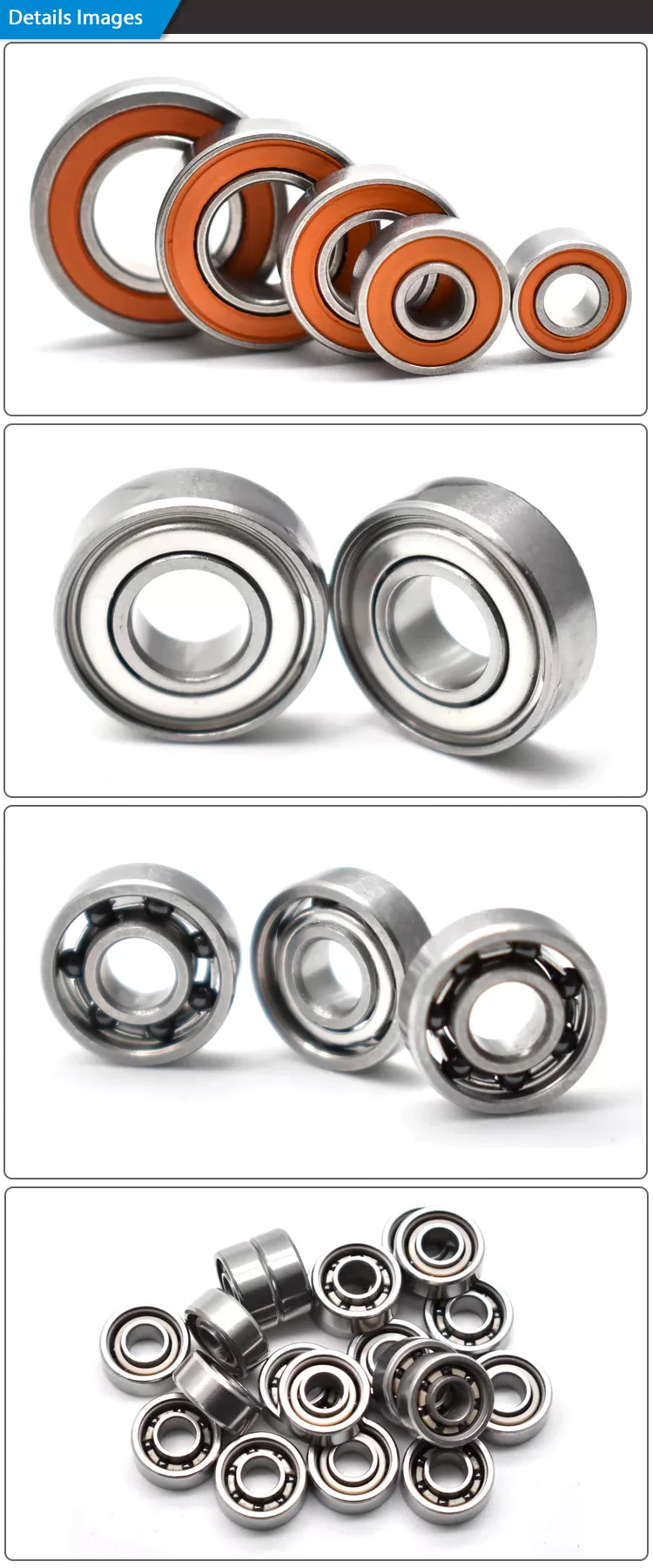
Miniature bearings

Although miniature ball bearings are a popular choice for small mechanical components, they are not without their challenges. They must be properly lubricated and stored in clean rooms. A strand of hair could ruin a miniature bearing. Fortunately, manufacturers offer lubrication services and a “Clean Room” for customers to store their miniature bearings safely. Read on to learn more about these small bearings and how they can help you.
The size of a miniature ball bearing can vary significantly, but most types of these devices are available in sizes ranging from.040 inch to 1 eighth of an inch. Whether you need a small ball bearing for a miniature car or a tiny instrument, a miniature bearing can save space while still offering high performance. Many of these bearings are shielded to prevent dirt from entering and leakage of lubricant. They can be flanged or unflanged, and some miniature ball bearings have extended inner rings that are designed for easy plate mounting.
Miniature ball bearings are commonly made from stainless steel or chrome steel. Both metals have their advantages. Stainless steel is the most popular material for ball bearings, which allows for a high load capacity while being quiet. Because stainless steel is relatively inexpensive, many small instrument bearings are made entirely of stainless steel. The difference in price is minimal, as the amount of steel is relatively small. Stainless steel miniature bearings are the smallest and lightest of all types of miniature ball bearings.

Self-aligning ball bearings
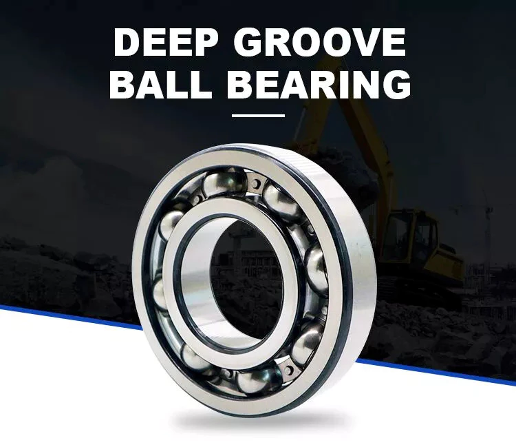
bearing
In the simplest terms, self-aligning ball bearings are ball bearings with flex shafts. If you’re looking for a ball bearing with a high degree of precision, you’ll want to choose 1 with a flex shaft, which means it can adjust to the proper orientation of the bearing’s flex shaft. Ball bearings with flex shafts are also recommended. But, what are these bearings?
Self-aligning ball bearings are made with 2 rows of balls and a common sphered raceway on the outer ring. As a result, they can accommodate small errors in shaft alignment and mounting. The CZPT brand is especially suitable for high-speed applications requiring greater running accuracy. The self-alignment mechanism is enabled by the fact that the balls are placed in 2 rows on either side of the sphered raceway in the outer ring. These 2 rows of balls also promote reduced friction and wear.
Another type of self-aligning ball bearings is a double-row design. They feature a common sphered raceway on the outer ring, a hollow spherical ring, and a cage that rotates relative to it. A self-aligning ball bearing is used in applications where shaft misalignment is a problem, such as conveying equipment. They are also used in simple woodworking machinery and ventilators.

Ceramic ball bearings

Ceramic ball bearings have several advantages over steel or metal bearings. These include increased acceleration capability, reduced friction, improved wear-resistance, and higher speeds. The United States holds the leading position in the global ceramic ball bearings market thanks to a rebounding motor vehicle production and healthy fixed investment environment. In the United States, there are 3 primary markets for ceramic ball bearings: healthcare, automotive, and aerospace. Here are the main benefits of ceramic ball bearings:
Hybrid ball bearings are also available. Hybrid bearings feature traditional metal rings and silicon nitride (ceramic) balls. Hybrid bearings offer important performance advantages over all-steel bearings, and they are more affordable. However, full ceramic ball bearings have all ceramic parts, and are best suited for machines that require high precision. These types of bearings also resist corrosion and wear.
Compared to steel ball bearings, ceramic balls are lighter than steel. They are also less dense, which means less friction and therefore less heat. Additionally, ceramic balls operate at higher speeds than steel balls, which increases their durability and longevity. But they are still not as strong as steel bearings. And because of their reduced density, they are much cheaper to manufacture. Therefore, they are an excellent choice for many applications. You can expect them to last much longer than steel bearings.

Steel carbon ball bearings

High precision G25 ball bearings are made of the highest grade chrome steel and hot forged from bar stock. Statistical process control and exacting atmospheres help ensure uniform hardness and microstructure. Moreover, these bearings are of the highest quality, with fine surface finish and a tight tolerance. This makes them the most widely used and reliable choice for industrial and automotive applications. However, there are some considerations that should be taken into account before acquiring a steel carbon ball bearing.
Generally, AFBMA grade 200 is the standard hardness specification for this material. AFBMA grade 100 can also be obtained with great difficulty. Despite the high hardness of steel carbon ball bearings, their outer surface is just a thin hardened shell, so a special micro hardness test is needed to evaluate them. In addition to the hardness, steel balls are easily machined and ground. Some manufacturers even offer stainless steel ball bearings and ball sets.
Another factor that makes steel carbon ball bearings so valuable is their precision. They can give precise measurements, which makes them ideal for low and medium-speed applications. Due to their high precision and durability, steel carbon ball bearings can be used in many applications, from conveyor machines to roller skates. However, you should be aware that the material used to produce these bearings is not suitable for applications in which they are exposed to water and gases. Further, they are also noisy and heavy, and must be installed properly in a manufacturing environment.

Stainless steel ball bearings
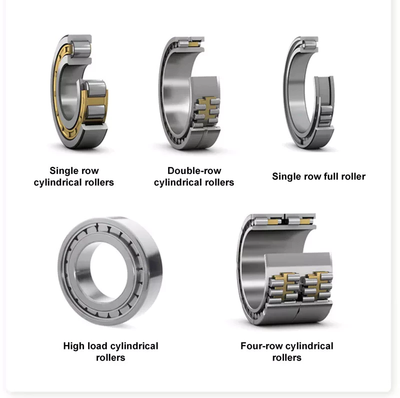
bearing
Stainless steel ball bearings are made from a high-quality type of stainless steel, 440C, which offers optimal corrosion and abrasion resistance. These bearings are also durable and rust-free, and are suitable for a variety of applications. Among others, stainless steel ball bearings are used in beverage and food processing plants, pharmaceuticals, pulp and paper mills, marine environments, and freezers.
Stainless steel bearings are available in various grades. For example, AISI 440C offers corrosion resistance, while the DD400 is specifically designed for marine applications. Both types of stainless steel are available in different forms, including open, shielded, and sealed. Stainless steel ball bearings can also be custom-made, as BL is known for producing customized bearings. There are also other materials that are available.
AISI type 316 stainless steel balls are ideal for marine applications and food processing. They have excellent resistance to most organic materials and are also used in medical devices and dispenser pumps. They are also strong enough to resist many petroleum products and are widely used in medical equipment and cosmetic applications. In addition, stainless steel balls can be plated to provide an additional layer of protection against chemicals. To understand how they differ, let’s take a look at some common types of stainless steel ball bearings.

Stainless steel

Stainless steel ball bearings can be used in various applications. Besides being corrosion resistant, they also last longer thanks to the Molded-Oil lubrication technology. Stainless steel ball bearings are clean units, which saves time and money in terms of maintenance, replacement, and downtime. But what are the advantages of stainless steel ball bearings? Let us discuss these benefits. Also, we’ll discuss their advantages and disadvantages.
Stainless steel ball bearings offer notable advantages, including corrosion resistance, increased strength, and improved stability under high temperatures. These qualities make them the ideal choice for special circumstances and demanding environments. However, you should be careful when choosing stainless steel bearings. There are several different types of stainless steel. Here’s a brief look at what makes them the best choice. And remember: Stainless steels are also recyclable. In fact, they can be recycled indefinitely.
They’re made from chrome alloy electric furnace steel, which is hardened for optimum service life and strength. They have the highest surface finish and dimensional accuracy. Advanced heat-treating processes increase their strength and anti-cracking abilities. And thanks to their unique materials, they’re corrosion-resistant. As a result, they’re more durable than other types of bearings. And since they’re made with a high-quality steel, you’ll save money in the long run.

Plastic ball bearings
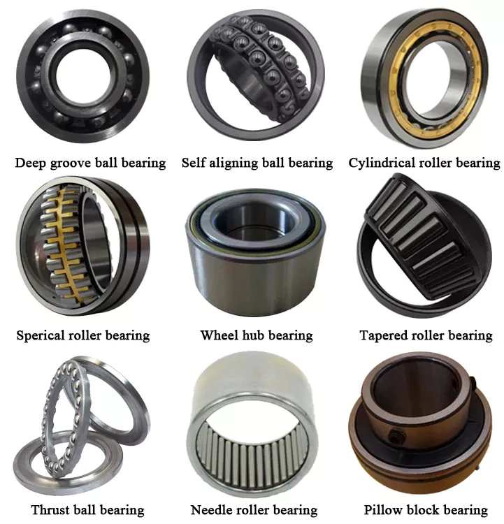
bearing
Plastic ball bearings were developed to meet the specific needs of applications where standard steel bearings would fail. Steel and 440C stainless steel are both susceptible to rusting when exposed to water, making them poor choices for applications involving food processing, swimming pools, and medical equipment. In addition to this, the plastic material is able to dampen vibrations and make the bearing virtually silent. Here’s what makes plastic ball bearings so great for these applications.
Plastic ball bearings are lightweight, corrosion-resistant, and offer a long service life. In addition to their low price, they can be easily cleaned and are incredibly durable. Motion plastics specialist igus has recently expanded its range of xiros polymer grooved ball bearings. These bearings are also FDA-compliant, lubricant-free, electrically insulating, and resistant to both temperature and media.
Plastic bearings are often mounted into other components like wheels, pulleys, and housings. In this way, the inner ring is essentially a profile of the pulley’s profile, and the outer ring is a shaft or fixing clip. The result is seamless integration of the bearing and the surrounding parts, which reduces the overall assembly time and costs. You can also use multiple plastic ball bearings in 1 application for more options.

China best Woodpecker Apex Locator Testing Cord File Holder Hook Dental Unit Parts     with high qualityChina best Woodpecker Apex Locator Testing Cord File Holder Hook Dental Unit Parts     with high quality

China Best Sales OEM Custom Ductile Iron Sand Casting Part Tractor Part/Metal Sand Machinery/Machined Steel /Mechanical/Motor/Casting/Cast/ Parts for Compressor Body with Best Sales

Product Description

OEM Custom GGG40 Ductile Iron Sand Casting Part

Product description :
 

Item Name
 
OEM Custom GGG40 Ductile Iron Sand Casting Part 
 General Products      
 Application/Service Area
 
Metal Parts Solution for Vehicle, Agriculture machine, Construction Machine, transportation equipment, Valve and Pump system, Agriculture machine metal Parts, engine bracket, truck chassis bracket, gear box , gear housing , gear cover, shaft, spline shaft , pulley, flange, connection pipe, pipe, hydraulic valve , valve housing ,Fitting , flange, wheel, fly wheel, oil pump housing, starter housing, coolant pump housing, transmission shaft , transmission gear, sprocket, chains etc.
 
 Main blank Process for Casting  
Sand Casting , Resin Sand Casting, Green Sand Casting, Shell Molding, Automatic Molding, Lost Wax Casting, Lost Foam Molding Casting
 
 Blanks Tolerance -Casting  Tolerance CT9-10 for  Machine Molding Process,
CT8-9 for Shell Molding and Lost Foam Molding Casting Process
CT10-11 for Manual Molding Sand  casting Process
 Applicable Material  
See Table Below (Ductile Iron Casting, Grey Iron Casting)
OR According to customer requirement
 
 Casting Blank Size  /Dimensions 2 mm-2000mm / 0.08inch-79inch  for casting iron, according to customer requirement
 Casting Blank Weight Range from 0.01kg-1000kg for casting iron
 Applicable Machining Process  
CNC Machining/ Lathing/ Milling/ Turning/ Boring/ Drilling/ Tapping/ Broaching/Reaming /Grinding/Honing and  etc.
 
 Machining Tolerance From 0.005mm-0.01mm-0.1mm
 Machined Surface Quality Ra 0.8-Ra3.2, according to customer requirement
 Applicable Heat Treatment  
Normalization , annealing, quenching and tempering, Case Hardening, Nitriding, Carbon Nitriding, Induction Quenching
 
 Applicable Finish Surface  Treatment  
Shot/sand blast, polishing, Surface passivation, Primer Painting , Powder coating, ED- Coating, Chromate Plating, zinc-plate, Dacromat coating, Finish Painting.
 
 MOQ For iron casting : 100pcs
For Machining : 50pcs
 Lead Time 45days from the receipt date of deposit for ductile iron casting

Company Introduction :

ZheJiang CZPT International Trading Company is a trading company which is specialized in castings,

forgings and machinery parts.

Our products include all kinds of raw castings to be made of ductile iron , grey iron , brass , stainless

steel and aluminums, machined castings and forged parts . To make these parts according to the

customers’ drawings , we have relative suitable production craft and equipments, such as resin sand ,

sand CZPT , hot core boxes , lost-wax , lost  foam and so on .

Specially for hydrant bodies and valves’ bodies, we have collected rich experience for these products in

the past 16 year’s actual production, Now we are proud of our products with good surface and high

quality material. Whatever,we have been trying our best to provide our customers with better quality

castings by improving  production crafts and more careful quality control.

Looking Forward To Receiving Your Kind Favorable Reply At Your Earliest!
 

Screw Shaft Types

A screw shaft is a cylindrical part that turns. Depending on its size, it is able to drive many different types of devices. The following information outlines the different types of screws, including their sizes, material, function, and applications. To help you select the right screw shaft, consider the following factors:
screwshaft

Size

A screw can come in a variety of shapes and sizes, ranging from a quarter to a quarter-inch in diameter. A screw is a cylindrical shaft with an inclined plane wrapped around it, and its main function is to fasten objects together by translating torque into a linear force. This article will discuss the dimensions of screws and how to determine the size of a screw. It is important to note that screw sizes can be large and small depending on the purpose.
The diameter of a screw is the diameter of its shaft, and it must match the inner diameter of its nuts and washers. Screws of a certain diameter are also called machine screws, and they can be larger or smaller. Screw diameters are measured on the shaft underneath the screw head. The American Society of Mechanical Engineers (ASME) standardized screw diameters in 3/50-inch to 16 (3/8-inch) inches, and more recently, sizes were added in U.S. fractions of an inch. While shaft and head diameters are standardized, screw length may vary from job to job.
In the case of the 2.3-mm screw group, the construct strength was not improved by the 1.2-mm group. The smaller screw size did not increase the strength of the construct. Further, ABS material did not improve the construct strength. Thus, the size of screw shaft is an important consideration in model design. And remember that the more complex your model is, the larger it will be. A screw of a given size will have a similar failure rate as a screw of a different diameter.
Although different screw sizes are widely used, the differences in screw size were not statistically significant. Although there are some limitations, screws of different sizes are generally sufficient for fixation of a metacarpal shaft fracture. However, further clinical studies are needed to compare screw sizes for fracture union rates. So, if you are unsure of what size of screw shaft you need for your case, make sure to check the metric chart and ensure you use the right one.
screwshaft

Material

The material of a screw shaft plays an important role in the overall performance of a screw. Axial and central forces act to apply torque to the screw, while external forces, such as friction, exert a bending moment. The torsional moments are reflected in the torque, and this causes the screw to rotate at a higher rate than necessary. To ensure the longevity of the screw, the material of the screw shaft should be able to handle the bending moment, while the diameter of the shaft should be small enough to avoid causing damage.
Screws are made from different metals, such as steel, brass, titanium, and bronze. Manufacturers often apply a top coating of chromium, brass, or zinc to improve corrosion resistance. Screws made of aluminum are not durable and are prone to rusting due to exposure to weather conditions. The majority of screw shafts are self-locking. They are suited for many applications, including threaded fasteners, C-clamps, and vises.
Screws that are fabricated with conical sections typically feature reduced open cross-sectional areas at the discharge point. This is a key design parameter of conical screw shafts. In fact, reductions of up to 72% are common across a variety of applications. If the screw is designed to have a hard-iron hanger bearing, it must be hardened. If the screw shaft is not hardened, it will require an additional lubricant.
Another consideration is the threads. Screw shafts are typically made of high-precision threads and ridges. These are manufactured on lathes and CNC machines. Different shapes require different materials. Materials for the screw shaft vary. There are many different sizes and shapes available, and each 1 has its own application. In addition to helical and conical screw shafts, different materials are also available. When choosing material, the best 1 depends on the application.
The life of the screw depends on its size, load, and design. In general, the material of the screw shaft, nut body, and balls and rollers determine its fatigue life. This affects the overall life of the screw. To determine whether a specific screw has a longer or shorter life, the manufacturer must consider these factors, as well as the application requirements. The material should be clean and free of imperfections. It should be smooth and free of cracks or flaking, which may result in premature failure.

Function

The function of a screw shaft is to facilitate the rotation of a screw. Screws have several thread forms, including single-start, double-start and multi-start. Each form has its own advantages and disadvantages. In this article we’ll explore each of them in detail. The function of a screw shaft can vary based on its design, but the following are common types. Here are some examples of screw shaft types and their purposes.
The screw’s torque enables it to lift objects. It can be used in conjunction with a bolt and nut to lift a load. Screws are also used to secure objects together. You can use them in screw presses, vises, and screw jacks. But their primary function is to hold objects together. Listed below are some of their main functions. When used to lift heavy loads, they can provide the required force to secure an object.
Screws can be classified into 2 types: square and round. Square threads are more efficient than round ones because they apply 0deg of angle to the nut. Square threads are also stronger than round threads and are often used in high-load applications. They’re generally cheaper to manufacture and are more difficult to break. And unlike square threads, which have a 0deg thread angle, these threads can’t be broken easily with a screwdriver.
A screw’s head is made of a series of spiral-like structures that extend from a cylindrical part to a tip. This portion of the screw is called the shank and is made of the smallest area. The shank is the portion that applies more force to the object. As the shaft extends from the head, it becomes thinner and narrow, forming a pointed tip. The head is the most important part of the screw, so it needs to be strong to perform its function.
The diameter of the screw shaft is measured in millimeters. The M8 screw has a thread pitch of 1.25 mm. Generally, the size of the screw shaft is indicated by the major and minor diameter. These dimensions are appended with a multiplication sign (M8x1).
screwshaft

Applications

The design of screws, including their size and shape, determines their critical rotating speeds. These speeds depend on the threaded part of the screw, the helix angle, and the geometry of the contact surfaces. When applied to a screw, these limits are referred to as “permissible speed limits.” These maximum speeds are meant for short periods of time and optimized running conditions. Continuous operation at these speeds can reduce the calculated life of a nut mechanism.
The main materials used to manufacture screws and screw shafts include steel, stainless steel, titanium, bronze, and brass. Screws may be coated for corrosion resistance, or they may be made of aluminium. Some materials can be threaded, including Teflon and nylon. Screw threads can even be molded into glass or porcelain. For the most part, steel and stainless steel are the most common materials for screw shafts. Depending on the purpose, a screw will be made of a material that is suitable for the application.
In addition to being used in fasteners, screw shafts are used in micrometers, drillers, conveyor belts, and helicopter blades. There are numerous applications of screw shafts, from weighing scales to measuring lengths. If you’re in the market for a screw, make sure to check out these applications. You’ll be happy you did! They can help you get the job done faster. So, don’t delay your next project.
If you’re interested in learning about screw sizing, then it’s important to know the axial and moment loads that your screws will experience. By following the laws of mechanics and knowing the load you can calculate the nominal life of your screw. You can also consider the effect of misalignment, uneven loading, and shocks on your screw. These will all affect the life of your screw. Then, you can select the right screw.

China Best Sales OEM Custom Ductile Iron Sand Casting Part Tractor Part/Metal Sand Machinery/Machined Steel /Mechanical/Motor/Casting/Cast/ Parts for Compressor Body     with Best SalesChina Best Sales OEM Custom Ductile Iron Sand Casting Part Tractor Part/Metal Sand Machinery/Machined Steel /Mechanical/Motor/Casting/Cast/ Parts for Compressor Body     with Best Sales

China high quality High Quality Charging Port Flex Cable + USB Dock Connector Charger Repair Parts for Apple iPad PRO 11 (2021) iPad PRO 3rd Generation A2377 A2459 A2301 A2460 with Best Sales

Product Description

Order description:

Product Description

1.100% Tested Well 1 by 1 before shipping.

2.Replace your broken or unworkable Charging Port Flex with a new one.

3.Perfect Fit For  iPad Pro 11 (2571) A2377 A2459 A2301 A2460 .

4.Feel Free to Contact us with any problems will reply within 24 hours .
5.We ship new replacement for defective directly without defective return .
6. Accpet Customized retail package .

Driveshaft structure and vibrations associated with it

The structure of the drive shaft is critical to its efficiency and reliability. Drive shafts typically contain claw couplings, rag joints and universal joints. Other drive shafts have prismatic or splined joints. Learn about the different types of drive shafts and how they work. If you want to know the vibrations associated with them, read on. But first, let’s define what a driveshaft is.
air-compressor

transmission shaft

As the demand on our vehicles continues to increase, so does the demand on our drive systems. Higher CO2 emission standards and stricter emission standards increase the stress on the drive system while improving comfort and shortening the turning radius. These and other negative effects can place significant stress and wear on components, which can lead to driveshaft failure and increase vehicle safety risks. Therefore, the drive shaft must be inspected and replaced regularly.
Depending on your model, you may only need to replace 1 driveshaft. However, the cost to replace both driveshafts ranges from $650 to $1850. Additionally, you may incur labor costs ranging from $140 to $250. The labor price will depend on your car model and its drivetrain type. In general, however, the cost of replacing a driveshaft ranges from $470 to $1850.
Regionally, the automotive driveshaft market can be divided into 4 major markets: North America, Europe, Asia Pacific, and Rest of the World. North America is expected to dominate the market, while Europe and Asia Pacific are expected to grow the fastest. Furthermore, the market is expected to grow at the highest rate in the future, driven by economic growth in the Asia Pacific region. Furthermore, most of the vehicles sold globally are produced in these regions.
The most important feature of the driveshaft is to transfer the power of the engine to useful work. Drive shafts are also known as propeller shafts and cardan shafts. In a vehicle, a propshaft transfers torque from the engine, transmission, and differential to the front or rear wheels, or both. Due to the complexity of driveshaft assemblies, they are critical to vehicle safety. In addition to transmitting torque from the engine, they must also compensate for deflection, angular changes and length changes.

type

Different types of drive shafts include helical shafts, gear shafts, worm shafts, planetary shafts and synchronous shafts. Radial protruding pins on the head provide a rotationally secure connection. At least 1 bearing has a groove extending along its circumferential length that allows the pin to pass through the bearing. There can also be 2 flanges on each end of the shaft. Depending on the application, the shaft can be installed in the most convenient location to function.
Propeller shafts are usually made of high-quality steel with high specific strength and modulus. However, they can also be made from advanced composite materials such as carbon fiber, Kevlar and fiberglass. Another type of propeller shaft is made of thermoplastic polyamide, which is stiff and has a high strength-to-weight ratio. Both drive shafts and screw shafts are used to drive cars, ships and motorcycles.
Sliding and tubular yokes are common components of drive shafts. By design, their angles must be equal or intersect to provide the correct angle of operation. Unless the working angles are equal, the shaft vibrates twice per revolution, causing torsional vibrations. The best way to avoid this is to make sure the 2 yokes are properly aligned. Crucially, these components have the same working angle to ensure smooth power flow.
The type of drive shaft varies according to the type of motor. Some are geared, while others are non-geared. In some cases, the drive shaft is fixed and the motor can rotate and steer. Alternatively, a flexible shaft can be used to control the speed and direction of the drive. In some applications where linear power transmission is not possible, flexible shafts are a useful option. For example, flexible shafts can be used in portable devices.
air-compressor

put up

The construction of the drive shaft has many advantages over bare metal. A shaft that is flexible in multiple directions is easier to maintain than a shaft that is rigid in other directions. The shaft body and coupling flange can be made of different materials, and the flange can be made of a different material than the main shaft body. For example, the coupling flange can be made of steel. The main shaft body is preferably flared on at least 1 end, and the at least 1 coupling flange includes a first generally frustoconical projection extending into the flared end of the main shaft body.
The normal stiffness of fiber-based shafts is achieved by the orientation of parallel fibers along the length of the shaft. However, the bending stiffness of this shaft is reduced due to the change in fiber orientation. Since the fibers continue to travel in the same direction from the first end to the second end, the reinforcement that increases the torsional stiffness of the shaft is not affected. In contrast, a fiber-based shaft is also flexible because it uses ribs that are approximately 90 degrees from the centerline of the shaft.
In addition to the helical ribs, the drive shaft 100 may also contain reinforcing elements. These reinforcing elements maintain the structural integrity of the shaft. These reinforcing elements are called helical ribs. They have ribs on both the outer and inner surfaces. This is to prevent shaft breakage. These elements can also be shaped to be flexible enough to accommodate some of the forces generated by the drive. Shafts can be designed using these methods and made into worm-like drive shafts.

vibration

The most common cause of drive shaft vibration is improper installation. There are 5 common types of driveshaft vibration, each related to installation parameters. To prevent this from happening, you should understand what causes these vibrations and how to fix them. The most common types of vibration are listed below. This article describes some common drive shaft vibration solutions. It may also be beneficial to consider the advice of a professional vibration technician for drive shaft vibration control.
If you’re not sure if the problem is the driveshaft or the engine, try turning on the stereo. Thicker carpet kits can also mask vibrations. Nonetheless, you should contact an expert as soon as possible. If vibration persists after vibration-related repairs, the driveshaft needs to be replaced. If the driveshaft is still under warranty, you can repair it yourself.
CV joints are the most common cause of third-order driveshaft vibration. If they are binding or fail, they need to be replaced. Alternatively, your CV joints may just be misaligned. If it is loose, you can check the CV connector. Another common cause of drive shaft vibration is improper assembly. Improper alignment of the yokes on both ends of the shaft can cause them to vibrate.
Incorrect trim height can also cause driveshaft vibration. Correct trim height is necessary to prevent drive shaft wobble. Whether your vehicle is new or old, you can perform some basic fixes to minimize problems. One of these solutions involves balancing the drive shaft. First, use the hose clamps to attach the weights to it. Next, attach an ounce of weight to it and spin it. By doing this, you minimize the frequency of vibration.
air-compressor

cost

The global driveshaft market is expected to exceed (xxx) million USD by 2028, growing at a compound annual growth rate (CAGR) of XX%. Its soaring growth can be attributed to several factors, including increasing urbanization and R&D investments by leading market players. The report also includes an in-depth analysis of key market trends and their impact on the industry. Additionally, the report provides a comprehensive regional analysis of the Driveshaft Market.
The cost of replacing the drive shaft depends on the type of repair required and the cause of the failure. Typical repair costs range from $300 to $750. Rear-wheel drive cars usually cost more. But front-wheel drive vehicles cost less than four-wheel drive vehicles. You may also choose to try repairing the driveshaft yourself. However, it is important to do your research and make sure you have the necessary tools and equipment to perform the job properly.
The report also covers the competitive landscape of the Drive Shafts market. It includes graphical representations, detailed statistics, management policies, and governance components. Additionally, it includes a detailed cost analysis. Additionally, the report presents views on the COVID-19 market and future trends. The report also provides valuable information to help you decide how to compete in your industry. When you buy a report like this, you are adding credibility to your work.
A quality driveshaft can improve your game by ensuring distance from the tee and improving responsiveness. The new material in the shaft construction is lighter, stronger and more responsive than ever before, so it is becoming a key part of the driver. And there are a variety of options to suit any budget. The main factor to consider when buying a shaft is its quality. However, it’s important to note that quality doesn’t come cheap and you should always choose an axle based on what your budget can handle.

China high quality High Quality Charging Port Flex Cable + USB Dock Connector Charger Repair Parts for Apple iPad PRO 11 (2021) iPad PRO 3rd Generation A2377 A2459 A2301 A2460     with Best SalesChina high quality High Quality Charging Port Flex Cable + USB Dock Connector Charger Repair Parts for Apple iPad PRO 11 (2021) iPad PRO 3rd Generation A2377 A2459 A2301 A2460     with Best Sales

China supplier OEM 1693315m91 1824403m91 3426773m1 3427773m1 Agricultural Machinery Tractor Tie Rod End Tractor Spare Parts near me shop

Product Description

Product Description

Warranty  1 Year Certification TS16949
Color Natural color Application Massey Ferguson
OEM NO. 1693315M91 MOQ 100 PCS
Engravement Customized Port HangZhou/ZheJiang

Specifications

1.Supply to USA,Europe,and so on
2.Matrial:Body C45 Ball Pin Cr40
3.Professional Perfomance Auto parts supplier

Detail Images

Other Products

Our Company

Packing & Delivery

Certification

Our Service

1. OEM Manufacturing welcome: Product, Package…
2. Sample order
3. We will reply you for your inquiry in 24 hours.
4. after sending, we will track the products for you once every 2 days, until you get the products. When you got the
goods, test them, and give me a feedback.If you have any questions about the problem, contact with us, we will offer
the solve way for you.

FAQ

Q1. What is your terms of packing?
A: Generally, we pack our goods in neutral white boxes and brown cartons. If you have legally registered patent,
we can pack the goods in your branded boxes after getting your authorization letters.

Q2. What is your terms of payment?
A: T/T 30% as deposit, and 70% before delivery. We’ll show you the photos of the products and packages
before you pay the balance.

Q3. What is your terms of delivery?
A: EXW, FOB, CFR, CIF, DDU.

Q4. How about your delivery time?
A: Generally, it will take 30 to 60 days after receiving your advance payment. The specific delivery time depends
on the items and the quantity of your order.

Q5. Can you produce according to the samples?
A: Yes, we can produce by your samples or technical drawings. We can build the molds and fixtures.

Q6. What is your sample policy?
A: We can supply the sample if we have ready parts in stock, but the customers have to pay the sample cost and
the courier cost.

Q7. Do you test all your goods before delivery?
A: Yes, we have 100% test before delivery

Q8: How do you make our business long-term and good relationship?
A:1. We keep good quality and competitive price to ensure our customers benefit ;
2. We respect every customer as our friend and we sincerely do business and make friends with them,
no matter where they come from.

The Functions of Splined Shaft Bearings

Splined shafts are the most common types of bearings for machine tools. They are made of a wide variety of materials, including metals and non-metals such as Delrin and nylon. They are often fabricated to reduce deflection. The tooth profile will become deformed with time, as the shaft is used over a long period of time. Splined shafts are available in a huge range of materials and lengths.

Functions

Splined shafts are used in a variety of applications and industries. They are an effective anti-rotational device, as well as a reliable means of transmitting torque. Other types of shafts are available, including key shafts, but splines are the most convenient for transmitting torque. The following article discusses the functions of splines and why they are a superior choice. Listed below are a few examples of applications and industries in which splines are used.
Splined shafts can be of several styles, depending on the application and mechanical system in question. The differences between splined shaft styles include the design of teeth, overall strength, transfer of rotational concentricity, sliding ability, and misalignment tolerance. Listed below are a few examples of splines, as well as some of their benefits. The difference between these styles is not mutually exclusive; instead, each style has a distinct set of pros and cons.
A splined shaft is a cylindrical shaft with teeth or ridges that correspond to a specific angular position. This allows a shaft to transfer torque while maintaining angular correspondence between tracks. A splined shaft is defined as a cylindrical member with several grooves cut into its circumference. These grooves are equally spaced around the shaft and form a series of projecting keys. These features give the shaft a rounded appearance and allow it to fit perfectly into a grooved cylindrical member.
While the most common applications of splines are for shortening or extending shafts, they can also be used to secure mechanical assemblies. An “involute spline” spline has a groove that is wider than its counterparts. The result is that a splined shaft will resist separation during operation. They are an ideal choice for applications where deflection is an issue.
A spline shaft’s radial torsion load distribution is equally distributed, unless a bevel gear is used. The radial torsion load is evenly distributed and will not exert significant load concentration. If the spline couplings are not aligned correctly, the spline connection can fail quickly, causing significant fretting fatigue and wear. A couple of papers discuss this issue in more detail.
splineshaft

Types

There are many different types of splined shafts. Each type features an evenly spaced helix of grooves on its outer surface. These grooves are either parallel or involute. Their shape allows them to be paired with gears and interchange rotary and linear motion. Splines are often cold-rolled or cut. The latter has increased strength compared to cut spines. These types of shafts are commonly used in applications requiring high strength, accuracy, and smoothness.
Another difference between internal and external splined shafts lies in the manufacturing process. The former is made of wood, while the latter is made of steel or a metal alloy. The process of manufacturing splined shafts involves cutting furrows into the surface of the material. Both processes are expensive and require expert skill. The main advantage of splined shafts is their adaptability to a wide range of applications.
In general, splined shafts are used in machinery where the rotation is transferred to an internal splined member. This member can be a gear or some other rotary device. These types of shafts are often packaged together as a hub assembly. Cleaning and lubricating are essential to the life of these components. If you’re using them on a daily basis, you’ll want to make sure to regularly inspect them.
Crowned splines are usually involute. The teeth of these splines form a spiral pattern. They are used for smaller diameter shafts because they add strength. Involute splines are also used on instrument drives and valve shafts. Serration standards are found in the SAE. Both kinds of splines can also contain a ball bearing for high torque. The difference between the 2 types of splines is the number of teeth on the shaft.
Internal splines have many advantages over external ones. For example, an internal spline shaft can be made using a grinding wheel instead of a CNC machine. It also uses a more accurate and economical process. Furthermore, it allows for a shorter manufacturing cycle, which is essential when splining high-speed machines. In addition, it stabilizes the relative phase between the spline and thread.
splineshaft

Manufacturing methods

There are several methods used to fabricate a splined shaft. Key and splined shafts are constructed from 2 separate parts that are shaped in a synchronized manner to transfer torque uniformly. Hot rolling is 1 method, while cold rolling utilizes low temperatures to form metal. Both methods enhance mechanical properties, surface finishes, and precision. The advantage of cold rolling is its cost-effectiveness.
Cold forming is 1 method, as well as machining and assembling. Cold forming is a unique process that allows the spline to be shaped to the desired shape. The resulting shape provides maximum contact area and torsional strength. Standard splines are available in standard sizes, but custom lengths can also be ordered. CZPT offers various auxiliary equipment, such as mating sleeves and flanged bushings.
Cold forging is another method. This method produces long splined shafts that are used in automobile propellers. After the spline portion is cut out, it is worked on in a hobbing machine. Work hardening enhances the root strength of the splined portion. It can be used for bearings, gears, and other mechanical components. Listed below are the manufacturing methods for splined shafts.
Parallel splines are the simplest of the splined shaft manufacturing methods. Parallel splines are usually welded to shafts, while involute splines are made of metal or non-metals. Splines are available in a wide variety of lengths and materials. The process is usually accompanied by a process called milling. The workpiece rotates to produce the serrated surface.
Splines are internal or external grooves in a splined shaft. They work in combination with keyways to transfer torque. Male and female splines are used in gears. Female and male splines correspond to 1 another to ensure proper angular correspondence. Involute splines have more surface area and thus are stronger than external splines. Moreover, they help the shaft fit into a grooved cylindrical member without misalignment.
A variety of other methods of manufacturing a splined shaft can be used to produce a splined shaft. Spline shafts can be produced using broaching and shaping, 2 precision machining methods. Broaching uses a metal tool with successively larger teeth to remove metal and create ridges and holes in the surface of a material. However, this process is expensive and requires special expertise.
splineshaft

Applications

The splined shaft is a mechanical component with a helix-like shape formed by the equal spacing of grooves in a circular ring. The splines can either have parallel or involute sides. The splines minimize stress concentration in stationary joints and can be used in both rotary and linear motion. In some cases, splines are rolled rather than cut. The latter is more durable than cut splines and is often used in applications requiring high strength, accuracy, and smooth finish.
Splined shafts are commonly made of carbon steel. This alloy steel has a low carbon content, making it easy to work with. Carbon steel is a great choice for splines because it is malleable. Generally, high-quality carbon steel provides a consistent motion. Steel alloys are also available that contain nickel, chromium, copper, and other metals. If you’re unsure of the right material for your application, you can consult a spline chart.
Splines are a versatile mechanical component. They are easy to cut and fit. Splines can be internal or external, with teeth positioned at equal intervals on both sides of the shaft. This allows the shaft to engage with the hub around the entire circumference of the hub. It also increases load capacity by creating a constant multiple-tooth point of contact with the hub. For this reason, they’re used extensively in rotary and linear motion.
Splined shafts are used in a wide variety of industries. CZPT Inc. offers custom and standard splined shafts for a variety of applications. When choosing a splined shaft for a specific application, consider the surrounding mated components, torque requirements, and size requirements. These 3 factors will make it the ideal choice for your rotary equipment. And you’ll be pleased with the end result!
There are many types of splines and their applications are endless. They transfer torque and angular misalignment between parts, and they also enable the axial rotation of assembled components. Therefore, splines are an essential component of machinery and are used in a wide range of applications. This type of shaft can be found in various types of machines, from household appliances to industrial machinery. So, the next time you’re looking for a splined shaft, make sure you look for a splined one.

China supplier OEM 1693315m91 1824403m91 3426773m1 3427773m1 Agricultural Machinery Tractor Tie Rod End Tractor Spare Parts     near me shop China supplier OEM 1693315m91 1824403m91 3426773m1 3427773m1 Agricultural Machinery Tractor Tie Rod End Tractor Spare Parts     near me shop

China supplier Automatic Mini Egg Incubator Spare Parts Flashlight Egg Tester near me manufacturer

Product Description

Automatic mini egg incubator spare parts flashlight egg tester


  Brand   huatuo  
  Voltage   12V  
  Size   12*12*2.5cm  
  Model   HT48/56/96/112  
  Name   rgg tester  
  Current   0.4/0.25A  
  Weight   0.15kg  
  Noise   <=40DBA  
  Package   color box  


Product Description


Company Information


Our Services


Trade patterns 


1. Lead time: 3-5 working days after payment 


2. MOQ: 1 set. 


3.30% deposit+ balance payment T/T;L/C, escrow, western union ,money gram.


4. Loading Port: HangZhou, HangZhou, HangZhou, HangZhou


 Import process 


1. We will prepare goods after payment 


2. We will send goods to EMS company or shipping company . 


3. We will give you tracking number or Bill of loading when your goods is on the way  


4. Finally your goods will arrive your address or shipping port .


FAQ


  Q: First time import, how can I believe that you would send the egg incubator I ordered? 
A: We are verified company by Alibaba ,to make transaction success, we support and recommend ESRCOW or LC . 
Q: How to ensure that the egg incubator  I received is undamaged? 
A: Our package is standard for shipping, before pick up , please confirm the egg incubator you recieved is undamaged. We’ve bought insurance for you, if damaged, we or ship company will take the responsibility. 
Q: What aftersales service or any questions about the egg incubator I bought? 
A: This egg incubator enjoys 3 years warranty , any problem , I am on line from 9 am to 12 pm, or you can send me mail , will reply you within 12 hours.


 If you have any questions or want to know more details about our goods,please contact me soon.

How to Design a Forging Spur Gear

Before you start designing your own spur gear, you need to understand its main components. Among them are Forging, Keyway, Spline, Set screw and other types. Understanding the differences between these types of spur gears is essential for making an informed decision. To learn more, keep reading. Also, don’t hesitate to contact me for assistance! Listed below are some helpful tips and tricks to design a spur gear. Hopefully, they will help you design the spur gear of your dreams.
Gear

Forging spur gears

Forging spur gears is 1 of the most important processes of automotive transmission components. The manufacturing process is complex and involves several steps, such as blank spheroidizing, hot forging, annealing, phosphating, and saponification. The material used for spur gears is typically 20CrMnTi. The process is completed by applying a continuous through extrusion forming method with dies designed for the sizing band length L and Splitting angle thickness T.
The process of forging spur gears can also use polyacetal (POM), a strong plastic commonly used for the manufacture of gears. This material is easy to mold and shape, and after hardening, it is extremely stiff and abrasion resistant. A number of metals and alloys are used for spur gears, including forged steel, stainless steel, and aluminum. Listed below are the different types of materials used in gear manufacturing and their advantages and disadvantages.
A spur gear’s tooth size is measured in modules, or m. Each number represents the number of teeth in the gear. As the number of teeth increases, so does its size. In general, the higher the number of teeth, the larger the module is. A high module gear has a large pressure angle. It’s also important to remember that spur gears must have the same module as the gears they are used to drive.

Set screw spur gears

A modern industry cannot function without set screw spur gears. These gears are highly efficient and are widely used in a variety of applications. Their design involves the calculation of speed and torque, which are both critical factors. The MEP model, for instance, considers the changing rigidity of a tooth pair along its path. The results are used to determine the type of spur gear required. Listed below are some tips for choosing a spur gear:
Type A. This type of gear does not have a hub. The gear itself is flat with a small hole in the middle. Set screw gears are most commonly used for lightweight applications without loads. The metal thickness can range from 0.25 mm to 3 mm. Set screw gears are also used for large machines that need to be strong and durable. This article provides an introduction to the different types of spur gears and how they differ from 1 another.
Pin Hub. Pin hub spur gears use a set screw to secure the pin. These gears are often connected to a shaft by dowel, spring, or roll pins. The pin is drilled to the precise diameter to fit inside the gear, so that it does not come loose. Pin hub spur gears have high tolerances, as the hole is not large enough to completely grip the shaft. This type of gear is generally the most expensive of the three.
Gear

Keyway spur gears

In today’s modern industry, spur gear transmissions are widely used to transfer power. These types of transmissions provide excellent efficiency but can be susceptible to power losses. These losses must be estimated during the design process. A key component of this analysis is the calculation of the contact area (2b) of the gear pair. However, this value is not necessarily applicable to every spur gear. Here are some examples of how to calculate this area. (See Figure 2)
Spur gears are characterized by having teeth parallel to the shafts and axis, and a pitch line velocity of up to 25 m/s is considered high. In addition, they are more efficient than helical gears of the same size. Unlike helical gears, spur gears are generally considered positive gears. They are often used for applications in which noise control is not an issue. The symmetry of the spur gear makes them especially suitable for applications where a constant speed is required.
Besides using a helical spur gear for the transmission, the gear can also have a standard tooth shape. Unlike helical gears, spur gears with an involute tooth form have thick roots, which prevents wear from the teeth. These gears are easily made with conventional production tools. The involute shape is an ideal choice for small-scale production and is 1 of the most popular types of spur gears.

Spline spur gears

When considering the types of spur gears that are used, it’s important to note the differences between the two. A spur gear, also called an involute gear, generates torque and regulates speed. It’s most common in car engines, but is also used in everyday appliances. However, 1 of the most significant drawbacks of spur gears is their noise. Because spur gears mesh only 1 tooth at a time, they create a high amount of stress and noise, making them unsuitable for everyday use.
The contact stress distribution chart represents the flank area of each gear tooth and the distance in both the axial and profile direction. A high contact area is located toward the center of the gear, which is caused by the micro-geometry of the gear. A positive l value indicates that there is no misalignment of the spline teeth on the interface with the helix hand. The opposite is true for negative l values.
Using an upper bound technique, Abdul and Dean studied the forging of spur gear forms. They assumed that the tooth profile would be a straight line. They also examined the non-dimensional forging pressure of a spline. Spline spur gears are commonly used in motors, gearboxes, and drills. The strength of spur gears and splines is primarily dependent on their radii and tooth diameter.
SUS303 and SUS304 stainless steel spur gears

Stainless steel spur gears are manufactured using different techniques, which depend on the material and the application. The most common process used in manufacturing them is cutting. Other processes involve rolling, casting, and forging. In addition, plastic spur gears are produced by injection molding, depending on the quantity of production required. SUS303 and SUS304 stainless steel spur gears can be made using a variety of materials, including structural carbon steel S45C, gray cast iron FC200, nonferrous metal C3604, engineering plastic MC901, and stainless steel.
The differences between 304 and 303 stainless steel spur gears lie in their composition. The 2 types of stainless steel share a common design, but have varying chemical compositions. China and Japan use the letters SUS304 and SUS303, which refer to their varying degrees of composition. As with most types of stainless steel, the 2 different grades are made to be used in industrial applications, such as planetary gears and spur gears.
Gear

Stainless steel spur gears

There are several things to look for in a stainless steel spur gear, including the diametral pitch, the number of teeth per unit diameter, and the angular velocity of the teeth. All of these aspects are critical to the performance of a spur gear, and the proper dimensional measurements are essential to the design and functionality of a spur gear. Those in the industry should be familiar with the terms used to describe spur gear parts, both to ensure clarity in production and in purchase orders.
A spur gear is a type of precision cylindrical gear with parallel teeth arranged in a rim. It is used in various applications, such as outboard motors, winches, construction equipment, lawn and garden equipment, turbine drives, pumps, centrifuges, and a variety of other machines. A spur gear is typically made from stainless steel and has a high level of durability. It is the most commonly used type of gear.
Stainless steel spur gears can come in many different shapes and sizes. Stainless steel spur gears are generally made of SUS304 or SUS303 stainless steel, which are used for their higher machinability. These gears are then heat-treated with nitriding or tooth surface induction. Unlike conventional gears, which need tooth grinding after heat-treating, stainless steel spur gears have a low wear rate and high machinability.

China supplier Automatic Mini Egg Incubator Spare Parts Flashlight Egg Tester     near me manufacturer China supplier Automatic Mini Egg Incubator Spare Parts Flashlight Egg Tester     near me manufacturer

China high quality OEM Plated Zinc Precision Pressure Casting Auto Parts with Hot selling

Product Description

Product Description

Model Number OEM
Product Material OEM
Product Name: machined part
Application: Used in custom machinery
Drawing Format PDF/DWG/DXF/IGS/STEP,etc
Production Equipment: CNC machining certer
QC: Full checking
Clients’ requirements Supplying material and dimension report
Certification: ISO 9001:2015
Brand Name: Custom-made
Dimensions Per clients’ drawings
Surface: Self color and Anodizing
Packaging: Per clients’ specifications

ABOUT US

     CZPT is top manufacturer of custom metal parts for kinds of fields. We have been in custom metal parts field for nearly 15 years, with ISO9001:2015 certification. We are specialized in manufacturing custom precision castings and CNC machining parts according to our customers’ specifications. Our Clients range from Europe to North America, including TOP 500 enterprises.
     Due to continuous expanding of business, we invested a new building which was built in 2016 occupying an area of more than 3000 squaremeters. We have 2 production lines: precision steel castings; and precision CNC and turning parts.
Packing and Shipping:
Conventional packaging: carton, can be customized according to customer needs;
Transportation: express, sea and air freight are supported.

See below for reference:

Professional Certificate:

FAQ

Q1: How Can I Get metal parts Sample?

A: It depends on your drawings or samples. Usually for castings, we will send out samples after we finish toolings. And it will take 15-20 days.

For machining parts, it will usually take 10 days.

Q2: What is The Process Of an Order?

A: Send Your Detailed Request→Feedback With Quotation→Confirm Quotation & Make Payment→Make samples→Sample Test(Approval)→Mass Production→Quality Checking→Delivery→After Service→Repeat Order

Q3: What is the Shipping Method?

A: For samples we will send out by international express service or by air.

For mass-production, it depends on weight and volume, usually by air or by sea.

Q4: Can You Give Me Help If My Products are Very Urgent?

A: Yes, Of Course, We Will Try Our Best to Give You Help. We will make special production schedule to Produce.

Q5: I Want to Keep Our Design in Secret,Can We Sign NDA?

A: Sure! We Will usually Sigh NDA according to our clients’ request.

And we will not release your design to third party.


How Metal Fabrication Benefits Agricultural Parts

agricultural parts

If you own an agricultural farm, you probably have a variety of different kinds of agricultural parts. These include tractors, hand tools, and other types of farm implements. Here, you’ll learn how to identify different parts and the importance of knowing what they do. Then, you can order them online to have them shipped directly to you. You can also contact different agricultural equipment dealers to find out where to buy agricultural parts. Regardless of where you get them, they’ll be worth the investment.
agriculturalparts

Metal fabricated agricultural parts

Regardless of the industry, metal fabricated agricultural parts can benefit a farm. For starters, metal fabricated parts are easier to replace than alternatives. Because metal is stronger than plastic, these parts can be made lighter. This means faster equipment movement and increased productivity. Metal can also be easily customized, allowing for a custom-made product. The benefits of metal fabrication extend far beyond the agricultural industry. Listed below are several of the benefits of using metal fabricated parts.
Agricultural equipment is exposed to harsh weather conditions. This is why it is imperative that metal fabricated agricultural parts are made with durable materials. Additionally, metal fabricated parts have a lower chance of corroding, which helps keep equipment running more efficiently. With such a long list of benefits, it’s easy to see why metal fabricated parts are so popular with farmers. And if your company needs agricultural equipment parts that can withstand the elements, you can depend on Hynes Industries.
Agricultural equipment requires metal parts that can withstand the rigorous workloads. As a trusted vendor, Evan’s Manufacturing provides comprehensive metal fabrication services for agricultural equipment. With our advanced laser cutting services, you can rest assured that your metal parts are in good hands. You’ll be able to make adjustments without affecting the integrity of the metal. And thanks to our streamlined process, the quality of your fabricated parts is unrivaled.
Whether you need a custom fitout for a new piece of farm equipment, or a new design for an existing piece, metal fabrication can help. Custom fitouts not only improve the comfort of the operator, but also increase the durability of your farm machinery. Almost every type of metal fabrication process is used in the agricultural industry. These include brazing, welding, soldering, drilling, milling, and laser engraving.
As the manufacturing process of agricultural machinery becomes increasingly automated, sheet metal fabrication has become an important part of the production process. This process allows for more precise and accurate processing of holes of various shapes and sizes, and the cost of production is lowered significantly. Additionally, because of its precision and stability, sheet metal fabrication is perfect for farming. Moreover, it’s easy to teach and maintain automated processes. With these machines, farmers can make small batches easily, improving the efficiency of agricultural production.
agriculturalparts

Agricultural machinery manufacturers

Agricultural machinery is a highly technological industry with a large market for OEM parts. The demand for agricultural equipment is expected to reach $118.2 billion by 2025, which is higher than the previous forecast. Today, modern tech developments have increased the productivity and profitability of farms, making it more profitable to use farm equipment. Moreover, the availability of OEM parts is a key driving factor for the market growth. The agricultural equipment market will see continued growth as manufacturers focus on safety, quality, and consistent improvement of their products.
AGCO Corporation is an agricultural machinery manufacturer based in Duluth, Georgia. It was formed through a merger with Allis-Chalmers in 1990. The company’s growth has been achieved through numerous acquisitions in farm machinery. It first acquired the Hesston forage and hay line from Fiat, which included a 50% share in a manufacturing joint venture with Case IH. Moreover, it acquired the White tractor business from Allied Products to expand its dealer network.
Among the major factors contributing to the supply chain breakdown for farm equipment manufacturers is the outbreak of COVID-19. The pandemic has affected the supply chain in several ways, including reducing the availability of raw materials and component parts. It also has affected the labor force by causing temporary layoffs and illness. Furthermore, the shortage of steel is causing manufacturers to struggle to meet demand. As a result, the company has to delay shipments to meet customer demand.
In addition to the above factors, the rising cost of labor is another factor driving equipment sales. Using auto-guidance systems to match the yield of a crop is an effective way to maximize yield while minimizing environmental impact. Another major factor driving agricultural equipment sales is the increasing cost of agricultural labor across regions. This pay differential between industrial workers and those in the agricultural sector is 1 of the most common secular drivers for demand for agricultural equipment.
A large proportion of agricultural equipment is oversized for economic reasons. For instance, a combine can do 3 different processes at once. It can also travel across several states or even countries. The need for reliable transportation companies is another critical factor in the industry. The majority of companies in this industry are family-owned and operated. A good transportation network is essential to keep equipment on the road. This is a major challenge for the industry.
The European Union accounts for a large proportion of agricultural machinery manufacturing, with total output of 28 billion euros (2014). The top 3 countries for production are Germany, Italy, and France, with each country accounting for around 17 per cent of the global total. The majority of leading international manufacturers maintain several production sites across the continent. The products produced at these facilities are typically for high-end customers. They can also be purchased from a variety of independent sources.
agriculturalparts

Agricultural equipment dealers

Agricultural equipment dealerships are facing a changing landscape. Today’s consumers expect businesses to be online 24/7, have faster response times, and allow them to make payments more conveniently. To keep up with these expectations, more dealers are making the switch to mobile apps. These apps simplify all areas of business, from sales to service, and allow technicians to receive work orders directly on their mobile devices. In addition, the growth of ag equipment manufacturers is fueling the trend of consolidation among ag equipment dealers.
Video marketing is especially useful for agricultural equipment dealers. Agricultural equipment dealers can utilize video marketing from firms such as Kirkpatrick Creative. Unlike text, video allows marketers to connect emotionally with their customers, by showing them a face. It is much more difficult to establish this connection through text, so video is a great way to reach potential customers. If a customer is satisfied with the process, they are more likely to buy from them again.
To succeed in sales of agricultural equipment, candidates should possess a combination of equipment knowledge, communication skills, and tenacity. Sales compensation packages for this industry are heavily based on commissions, so new salespeople should be prepared to work without a guaranteed monthly check. Agricultural equipment dealers should be ready for this kind of change in the coming years and prepare their sales funnels to make the transition. In addition, they should make sure that their phone numbers are prominently displayed.
The laws governing agricultural equipment dealers vary from state to state. These laws protect farm equipment dealers by outlining their rights as a supplier and a manufacturer. While these laws may have some commonalities, they do have some differences, which makes them essential to fully understand. Several procedures which are legal in 1 state may not be allowed in another. For this reason, it is vital that the dealer understand the laws of his state and be familiar with the relevant legislation.
The shortage of labor in the agriculture sector is a major challenge for many growers. But the shortage of labor could spur sales of robotics and automation equipment that simplify the farming process. With the right tools, a farm can run more efficiently and reduce its worker headcount. Therefore, the lack of labor will continue to be a major problem for agricultural equipment dealers. With this in mind, it is imperative to choose the right dealer for the job.
The influx of new equipment has made it difficult for agricultural equipment manufacturers to meet demand. Many companies have struggled to get implements to dealerships on time, making the overall situation even more complicated. Agricultural equipment dealers have to wait weeks or even months for their new machines to be delivered to farmers. A tractor from John Deere, for instance, can take 5 or 6 weeks to arrive in a dealership. It can now take 18 to 22 weeks, depending on the size of the order.

China high quality OEM Plated Zinc Precision Pressure Casting Auto Parts     with Hot sellingChina high quality OEM Plated Zinc Precision Pressure Casting Auto Parts     with Hot selling

China wholesaler Ball Bearing Manufacturer China Factory Cixi Bearing Auto Parts Auto Parts with Great quality

Product Description

Specification

The type of  deep groove ball Bearing 6015 used in automobile, tractor, machinery, motor, water pump, agricultural machinery and textile machinery. Its wide application, simple design, non – separation, suitable for high – speed, reliable operation, low maintenance costs.The tight consistency between deep raceway and groove and ball enables deep raceway ball bearings to withstand axial loads in both directions in addition to radial loads.

Product Parameters

Application
1. Automatic controlling machine
2. Semi-conductor industry
3. General industry machinery
4. Medical equipment
5. Solar energy equipment
6. Machine tool
7. Parking system
8. High-speed rail and aviation transportation equipment, etc.

Packaging & Shipping 

Packaging Detail 1.Industrial Exporting Package
2. Individual plastic/Carton/pallet
3. As the customers’ requirements
Delivery Detail 30-45 days for normal order


About us

HangZhou Kent bearing company was established in 2003 and is 1 of the leading bearing manufacturers and exporters in China. Kent specializes in the design and production of high precision, high speed and low noise  groove ball bearings and pillow block bearings. At present, the Corporation has more than 1,000 employees, a fixed assets of 2 billion yuan, and produces 250 million sets of bearings annually. The Corporation’s products are widely used in more than 50 countries and regions under 2 independent brands, namely “BUGAO” and “NBKT”.In addition, we participate in major professional exhibitions at home and abroad every year.

Research and Development

Since 2003, the Corporation has set up a Research & Development Center equipped with multiple laboratories used for precision measurement, mechanical testing, lifespan testing, and physicochemical testing, to continuously upgrade its skills and raise its manufacturing standard and product’s precision. Our workshops are installed with a series of advanced numerically-controlled, grinding and assembly equipment that utilize centralized filtration and cooling systems. Together with the production equipment suppliers, we developed these grinding, ultra-precision, fully automated integrated production lines, and own the intellectual property rights. The precision level of the products are at P5 level and above, with noise level CZPT Z4, V4 and above. Some of our projects have exceeded the 30% precision reserves. Our products are widely used in electric motors, automobiles, motorcycles, household appliances, textile, electric tools and water pump equipment industries, both locally and globally.

Why choose us?
▄ HangZhou Kent bearing Co.,Ltd established in 2003, has been focused on high precision and low noise deep groove ball bearing research and manufacturing. Engaged in foreign trade for 16 years, we provide products for many industrial fields. We attach important to global production, Not only won wideapresd praise in the domestic market, but also gain the recognition of foreign market, such as European,Southeast Asian and Africa market.
▄ The company has more than 20 assembly lines, and through ISO9001:2000 quality management system certification, has a professional technical and service team, technical personnel proportion of more than 30%. Over the years, we have been adhering to the use of high-end raw material production, from the first to every step, with excellent product development capabilities and strict quality control, we continue to expand the product line and application range.
▄ To learn from the advanced level at home and abroad, to create their own high-quality bearings, is the CZPT pursuit of Kent bearing company. Uphold the “True quality is more durable, let the bearing move more quieter”
business philosophy, we have received many customers good praise.
▄ Good Warranty we take customer satisfaction and product quality as the first priority for us, we supply reliable warranties and good after-sales services.

FAQ
1.Q: Are you a factory or trading company?
    A: We are factory specialized in manufacturing and exporting bearings.
2.Q: Where is your factory located? How can I visit there?
    
A: Our factory located in HangZhou county, HangZhou city . You can fly to HangZhou Lishe International Airport directly. All our customers, from home or abroad,are warmly welcome to visit our factory.   
3.Q: Do you provide samples ? it is free charge?
    
A: Yes, we could offer the sample for free charge but do not pay the cost of freight.
4.Q: What is your main product?
    
A: We are making 10 series and total about 100 types of bearings.
5.Q: What is the MOQ for bearings?
    A: Our MOQ is 1000 pieces.

Contact us

Address: Mayan Industry Zone, Henghe Town, HangZhou, HangZhou, China

Types of Bevel Gears

Bevel Gears are used in a number of industries. They are used in wheeled excavators, dredges, conveyor belts, mill actuators, and rail transmissions. A bevel gear’s spiral or angled bevel can make it suitable for confined spaces. It is also used in robotics and vertical supports of rolling mills. You can use bevel gears in food processing processes. For more information on bevel gears, read on.
gear

Spiral bevel gear

Spiral bevel gears are used to transmit power between 2 shafts in a 90-degree orientation. They have curved or oblique teeth and can be fabricated from various metals. Bestagear is 1 manufacturer specializing in medium to large spiral bevel gears. They are used in the mining, metallurgical, marine, and oil fields. Spiral bevel gears are usually made from steel, aluminum, or phenolic materials.
Spiral bevel gears have many advantages. Their mesh teeth create a less abrupt force transfer. They are incredibly durable and are designed to last a long time. They are also less expensive than other right-angle gears. They also tend to last longer, because they are manufactured in pairs. The spiral bevel gear also reduces noise and vibration from its counterparts. Therefore, if you are in need of a new gear set, spiral bevel gears are the right choice.
The contact between spiral bevel gear teeth occurs along the surface of the gear tooth. The contact follows the Hertz theory of elastic contact. This principle holds for small significant dimensions of the contact area and small relative radii of curvature of the surfaces. In this case, strains and friction are negligible. A spiral bevel gear is a common example of an inverted helical gear. This gear is commonly used in mining equipment.
Spiral bevel gears also have a backlash-absorbing feature. This feature helps secure the thickness of the oil film on the gear surface. The shaft axis, mounting distance, and angle errors all affect the tooth contact on a spiral bevel gear. Adjusting backlash helps to correct these problems. The tolerances shown above are common for bevel gears. In some cases, manufacturers make slight design changes late in the production process, which minimizes the risk to OEMs.

Straight bevel gear

Straight bevel gears are among the easiest types of gears to manufacture. The earliest method used to manufacture straight bevel gears was to use a planer equipped with an indexing head. However, improvements have been made in manufacturing methods after the introduction of the Revacycle system and the Coniflex. The latest technology allows for even more precise manufacturing. Both of these manufacturing methods are used by CZPT. Here are some examples of straight bevel gear manufacturing.
A straight bevel gear is manufactured using 2 kinds of bevel surfaces, namely, the Gleason method and the Klingelnberg method. Among the two, the Gleason method is the most common. Unlike other types of gear, the CZPT method is not a universal standard. The Gleason system has higher quality gears, since its adoption of tooth crowning is the most effective way to make gears that tolerate even small assembly errors. It also eliminates the stress concentration in the bevelled edges of the teeth.
The gear’s composition depends on the application. When durability is required, a gear is made of cast iron. The pinion is usually 3 times harder than the gear, which helps balance wear. Other materials, such as carbon steel, are cheaper, but are less resistant to corrosion. Inertia is another critical factor to consider, since heavier gears are more difficult to reverse and stop. Precision requirements may include the gear pitch and diameter, as well as the pressure angle.
Involute geometry of a straight bevel gear is often computed by varying the surface’s normal to the surface. Involute geometry is computed by incorporating the surface coordinates and the theoretical tooth thickness. Using the CMM, the spherical involute surface can be used to determine tooth contact patterns. This method is useful when a roll tester tooling is unavailable, because it can predict the teeth’ contact pattern.
gear

Hypoid bevel gear

Hypoid bevel gears are an efficient and versatile speed reduction solution. Their compact size, high efficiency, low noise and heat generation, and long life make them a popular choice in the power transmission and motion control industries. The following are some of the benefits of hypoid gearing and why you should use it. Listed below are some of the key misperceptions and false assumptions of this gear type. These assumptions may seem counterintuitive at first, but will help you understand what this gear is all about.
The basic concept of hypoid gears is that they use 2 non-intersecting shafts. The smaller gear shaft is offset from the larger gear shaft, allowing them to mesh without interference and support each other securely. The resulting torque transfer is improved when compared to conventional gear sets. A hypoid bevel gear is used to drive the rear axle of an automobile. It increases the flexibility of machine design and allows the axes to be freely adjusted.
In the first case, the mesh of the 2 bodies is obtained by fitting the hyperboloidal cutter to the desired gear. Its geometric properties, orientation, and position determine the desired gear. The latter is used if the desired gear is noise-free or is required to reduce vibrations. A hyperboloidal cutter, on the other hand, meshes with 2 toothed bodies. It is the most efficient option for modeling hypoid gears with noise concerns.
The main difference between hypoid and spiral bevel gears is that the hypoid bevel gear has a larger diameter than its counterparts. They are usually found in 1:1 and 2:1 applications, but some manufacturers also provide higher ratios. A hypoid gearbox can achieve speeds of 3 thousand rpm. This makes it the preferred choice in a variety of applications. So, if you’re looking for a gearbox with a high efficiency, this is the gear for you.

Addendum and dedendum angles

The addendum and dedendum angles of a bevel gear are used to describe the shape and depth of the teeth of the gear. Each tooth of the gear has a slightly tapered surface that changes in depth. These angles are defined by their addendum and dedendum distances. Addendum angle is the distance between the top land and the bottom surface of the teeth, while dedendum angle is the distance between the pitch surface and the bottom surface of the teeth.
The pitch angle is the angle formed by the apex point of the gear’s pitch cone with the pitch line of the gear shaft. The dedendum angle, on the other hand, is the depth of the tooth space below the pitch line. Both angles are used to measure the shape of a bevel gear. The addendum and dedendum angles are important for gear design.
The dedendum and addendum angles of a bevel gear are determined by the base contact ratio (Mc) of the 2 gears. The involute curve is not allowed to extend within the base diameter of the bevel gear. The base diameter is also a critical measurement for the design of a gear. It is possible to reduce the involute curve to match the involute curve, but it must be tangential to the involute curve.
The most common application of a bevel gear is the automotive differential. They are used in many types of vehicles, including cars, trucks, and even construction equipment. They are also used in the marine industry and aviation. Aside from these 2 common uses, there are many other uses for bevel gears. And they are still growing in popularity. But they’re a valuable part of automotive and industrial gearing systems.
gear

Applications of bevel gears

Bevel gears are used in a variety of applications. They are made of various materials depending on their weight, load, and application. For high-load applications, ferrous metals such as grey cast iron are used. These materials have excellent wear resistance and are inexpensive. For lower-weight applications, steel or non-metals such as plastics are used. Some bevel gear materials are considered noiseless. Here are some of their most common uses.
Straight bevel gears are the easiest to manufacture. The earliest method of manufacturing them was with a planer with an indexing head. Modern manufacturing methods introduced the Revacycle and Coniflex systems. For industrial gear manufacturing, the CZPT uses the Revacycle system. However, there are many types of bevel gears. This guide will help you choose the right material for your next project. These materials can withstand high rotational speeds and are very strong.
Bevel gears are most common in automotive and industrial machinery. They connect the driveshaft to the wheels. Some even have a 45-degree bevel. These gears can be placed on a bevel surface and be tested for their transmission capabilities. They are also used in testing applications to ensure proper motion transmission. They can reduce the speed of straight shafts. Bevel gears can be used in many industries, from marine to aviation.
The simplest type of bevel gear is the miter gear, which has a 1:1 ratio. It is used to change the axis of rotation. The shafts of angular miter bevel gears can intersect at any angle, from 45 degrees to 120 degrees. The teeth on the bevel gear can be straight, spiral, or Zerol. And as with the rack and pinion gears, there are different types of bevel gears.

China wholesaler Ball Bearing Manufacturer China Factory Cixi Bearing Auto Parts Auto Parts     with Great qualityChina wholesaler Ball Bearing Manufacturer China Factory Cixi Bearing Auto Parts Auto Parts     with Great quality

China wholesaler Combine Harvester Spare Parts near me manufacturer

Product Description

  WORLD combine harvester spare parts

Processing: According to different working condition,
Quality: The best quality in China
Dimension: As per OEM dimensions or Drawings
Surface: Anti-rust oil, painting, Zincification or as requested
Different surface treatment to protect against corrosion
Colors: Natural, black, yellow or as requested
Use: Replace world ruilong combine harvester parts
Feature: More durable material, at reasonable price
Package: Some pieces in 1 box, some boxes in 1 carton, some cartons in 1 pallet
Item Name: WORLD RUILONG combine harvester spare parts
Other advantage: Different model for choice at competitive price

Combine Advantage:
1. 10 years’ experience makes us more capable to guarantee the quality.
2. Combine parts were exported to more than 56 countries.
3. We are familiar with the market, can offer many helps in China.
4. Professional team workers will let the communication more convenient 
WORLD parts:
1.Popular models: Knife assembly: Knife head, knife section, Knife Guard, Hold down clip, Fastener.
2. According to different working condition, forged, machined and casting quality is available.
3. Ordered according to customers’ requirements, based on the sample or drawing
4. Special CZPT development.
5. Processing Craft:according to different working condition and different products
6. Brand: Combine Logo or your authorized Logo
7. MOQ: 100 PCS
8. Unit price: US$3-US$20 against different QTY
9. Loading port: ZheJiang , HangZhou
10. Place of origin: ZheJiang
11. Production against drawing or samples from customer
12. Payment terms: T/T, L/C, Western Union
14. Sample lead time: 10~15 days
15. Order lead time: within 45~60 days after prepayment received


Choosing the Right Ball Bearing for Your Application

When choosing a Ball Bearing, there are several things to consider. These factors include: the size, lubricant type, presence of corrosive agents, stray electrical currents, and more. It can be challenging to choose the right type, size, and type of ball bearing for your application. You should also carefully calculate the loads to determine the right size. Here are some tips for choosing the right Ball Bearing for your application.

Single-row

The single-row ball bearing is 1 of the most popular types of bearings. The inner and outer ring are designed with raceway grooves that are shaped slightly larger than the balls. This type of bearing has a low torque and can handle high-speed applications with minimal power loss. The radial dimensions of single-row ball bearings also vary, so it is possible to find 1 that fits your specific application. Besides the above-mentioned advantages, single-row ball bearings are also available with varying grease levels and are widely applicable to applications where the space is limited.
Single-row ball bearings are also called angular-contact ball bearings. Because of their single-row design, they are not separable and can accommodate a high-speed, heavy-duty application. Single-row angular-contact ball bearings can only handle axial load in 1 direction, and they must be installed in pairs for pure radial loads. Single-row ball bearings are a popular type of rolling bearings and can be used for a wide range of applications.
bearing

Self-aligning

The self-aligning ball bearing was invented by Sven Wingquist, a plant engineer for a textile company in Sweden. While he was responsible for making production as efficient as possible, he soon realized that the machinery he had in place wasn’t working as efficiently as it could. Although ball bearings are great for reducing friction, they were not flexible enough to compensate for misalignments in the machine.
Self-aligning ball bearings have 2 rows of balls and a common sphered raceway. The inner ring is curved and combines the 2 rows of balls into 1 cage. These bearings can tolerate shaft misalignment and compensate for static angular defects. They can be used in simple woodworking machinery, ventilators, and conveying equipment. They are often the preferred choice for applications where shaft alignment is an issue.

Ceramic

A Ceramic ball bearing is a type of high-performance bearing that is available in both full-ceramic and hybrid forms. The main differences between ceramic and steel ball bearings are their construction, lubrication, and mobility. High-quality ceramic ball bearings are durable, and they are ideal for corrosive and high-temperature applications. The material used to create these bearings helps prevent electrolytic corrosion. They are also ideal for reducing the friction and lubrication requirements.
Ceramic balls are harder and less brittle than steel balls, which gives them a higher degree of rigidity. Ceramics also have a higher hardness, with a hardness of Rc75-80 compared to Rc58-64 for steel balls. Their high compressive strength is approximately 5 to 7 times greater than steel. In addition, they have a very low coefficient of friction, which allows them to spin at higher speeds and with less friction. This increases their lifespan and durability, and decreases the energy needed to turn cranks.

Steel

Unlike traditional bearings, steel balls have a relatively uniform hardness. Carbon steel, for instance, is 2.1% carbon by weight. According to the American Iron and Steel Institute, copper content must be no more than 0.40% and manganese content should not be more than 1.65 g/cm3. After carbonizing, steel balls undergo a process called sizing, which improves their roundness geometry and hardness.
The main differences between steel ball bearings and ceramic ball bearings can be traced to their different materials. Ceramic balls are made from zirconium dioxide or silicon nitride. Silicon nitride is harder than steel and resists shocks. The result is increased speed and longer service life. Polyoxymethylene acetal (PMMA) bearing balls are known for their stiffness, strength, and tolerance, but are not as common as steel ball bearings.

Plastic

The most popular types of plastic ball bearings are made of polypropylene or PTFE. These bearings are used in applications requiring higher chemical resistance. Polypropylene is a structural polymer that offers excellent physical and chemical properties, including excellent resistance to organic solvents and degreasing agents. Its lightweight, low moisture absorption rate, and good heat resistance make it an excellent choice for high-temperature applications. However, plastic bearings are not without their drawbacks, especially when operating at very high temperatures or under heavy loads.
Compared to metal bearings, plastic ball-bearings do not require lubrication. They also are highly corrosion-resistant, making them an excellent choice for wash-down applications. They are also post-, autoclave-, and gamma sterilizable. Many conventional steel ball-bearings cannot handle the high temperatures of food processing or swimming pools. In addition to high temperature applications, plastic ball bearings are resistant to chemicals, including chlorine.
bearing

Glass

Plastic sliding bearings are molded bearings made of engineering plastic. With self-lubricating modification technology, these bearings can be produced by injection molding of plastic beads. They are widely used in various industries such as office equipment, fitness and automotive equipment. In addition to plastic bearings, glass balls are used in a variety of other applications, including medical equipment. Glass ball bearings have excellent corrosion resistance, excellent mechanical properties, and are electrically insulators.
Plastic ball bearings are made of all-plastic races and cages. These bearings are suitable for applications that are exposed to acids and alkalis. Because they are cheaper than glass balls, plastic ball bearings are popular in chemical-exposed environments. Stainless steel balls are also resistant to heat and corrosion. But the main disadvantage of plastic ball bearings is that they are not as strong as glass balls. So, if weight and noise is your main concern, consider using plastic balls instead.

Miniature

The global miniature ball bearing market is expected to reach US$ 2.39 Billion by 2027, at a CAGR of 7.2%. Growth in the region is attributed to technological advancement and government initiatives. Countries such as India and China are attracting FDIs and emphasizing the establishment of a global manufacturing hub. This is boosting the market for miniature ball bearings. The miniscule ball bearings are manufactured in small quantities and are very small.
Some manufacturers produce miniature ball bearings in different materials and designs. Chrome steel is the most popular material for miniature ball bearings because of its high load capacity, low noise properties, and lower cost. But the cost of stainless steel miniature bearings is low, since the amount of steel used is minimal. Stainless steel miniature bearings are the smallest in size. Therefore, you can choose stainless steel mini ball bearings for high-speed applications.

Angular-contact

Angular-contact ball bearings have 3 components: a cage, inner ring, and balls. Angular-contact ball bearings can support high axial and radial loads. Various design and manufacturing attributes make angular-contact ball bearings suitable for a variety of applications. Some features of this bearing type include a special lubricant, different cage materials, and different coatings.
The size of an angular-contact ball bearing is determined by the design units: outer ring width, axial load, and radial load. Depending on the type of application, an angular-contact ball bearing may be manufactured in double-row, triple-row, or quadruple-row configurations. Angular contact ball bearings can be classified according to their design units, which range from metric to imperial. A higher ABEC number means tighter tolerances. To determine the tolerance equivalent of a particular bearing, consult a standard Angular-contact ball bearing table.
Angular-contact ball bearings feature high and low-shoulder configurations. They have two-dimensional races that accommodate axial and radial loads. They are available in self-retaining units with solid inner and outer rings, and ball and cage assemblies. Cages made of cast and wrought brass are the most popular, but lightweight phenolic cages are also available. The latter is a better choice because it doesn’t absorb oil and has lower rolling friction.
bearing

Materials

When it comes to the construction of a ball bearing, high-quality raw materials are a crucial component. These materials not only affect the overall quality of a ball bearing, but also influence the cost. That’s why you should pay close attention to raw material quality. In addition to that, raw materials should be tested several times before the manufacturing process to ensure quality. Read on for some information about the different types of materials used to make ball bearings.
Steel is the most common material for ball bearings. Most ball bearings contain stainless steel balls, which are remarkably corrosion-resistant. They are also resistant to saltwater and alkalis. However, stainless steel balls are heavier than plastic ones, and they are also magnetic, which may be a drawback in some applications. If you’re looking for a metal-free option, glass balls are the way to go. They’re sturdy, lightweight, and resistant to a wide range of chemicals.

China wholesaler Combine Harvester Spare Parts     near me manufacturer China wholesaler Combine Harvester Spare Parts     near me manufacturer

China Custom Spare Parts of Chain Belt Grate for Rice Husk Fired Boiler with Hot selling

Product Description

Product Description:

The patent material RTSiCr,RQTSi4Mo, which is our company’s unique material. High temperature resistance, Special process, longer service life.

Detailed Images:

Features Advantages:

Grate Iron Material Types: HT150, HT200, HTCr2, RTSi5, RQTSI5,Cr16, HiSiCr, ZG40CR24 etc. Heating resistant from 550-1200ºC.
Available Fuels: Coal-fired(Anthracite, Brown coal, Peat), Biomass(Rice husk, Corncobs, Bagasse, Coconut shell, Palm shell,
                                    Palm fiber, Biomass briquettes), Solid Waste(Residential, Municipal, Medical, Industrial all waste).

Apply To: Steam boiler, Hot water boiler, Hot air furnace, Drying equipment, Heating company, Waste incinerator.

Packing & Delivery:

Main products:

Working process:

Company Profile:
HangZhou Sunshine Boiler Auxiliaries Co., Ltd., which is located in HangZhou, known as the Pearl of the North-surrounded by the Yellow Sea and the CZPT Sea, with green mountains and clear waters, picturesque scenery and pleasant climate. With convenient sea, land and air transportation, it is a port city in a civilized world.

The company was established in 1998 and now covers an area of more than 300,000 square meters, with a factory building area of more than 80,000 square meters. After more than 10 years of rapid integration and development, our company has now become a leading company in the boiler auxiliary machinery industry, and the company’s products are sold well both at home and abroad. The company now has fixed assets of 160 million yuan and more than 400 employees, including 105 professional and technical personnel. The grate has a market share of more than 20% in the country, and its production scale, automation level and single machine capacity are among the forefront of the same industry in the country. Reached long-term cooperative relations with more than 600 boiler plants and heating units across the country.

Certificate of utility model patent:

Instead of traditional structure

We improved and greated 1 type of big flake chain grate with duide block structure dricing system.

Material test:

The manufacturing of the chain grate is in accordaned with the standard of “JB/T 3271-2002”.

All high-temperature materials grate will be inspected strictly before leaving the factory.

FAQ:

1.Q: Can you give us a quotation right now?
A: Sorry, our products are all customized. Please give us your required dimension of capacity. Then we will make a design and quotation for you ASAP.

2. Q: Can you give us your price list?
A: Sorry, we don’t have any. Our products are all manufactured according to customers’ requirements.
3. Q: What is your MOQ?
A: 1 piece/set.
4. Q: Do you have any 1 in stock?
A:Yes. For the chain grate parts, we have in stock. Grates assembly are manufactured.
5. Q: Do you accept a special order?
A:Yes, we do. We can manufacture all kinds of casting products and grate,according to your technical drawings.
6. Q: Can you give us the technical drawing and data?
A:We will give you the overall dimension drawing for your plan and project. But the detailed drawing and data will be sent you after we signed the contract and confidentiality agreement.
7. Q: Do you provide after-sales service?
A: Yes, we do.Our productsare guaranteed for the wearing parts 1 year.
8. Q: Can your engineer come to our place for installation guide?
A:Yes, we can. We will provide a video and document for installation.And if necessary, we have professional installation team with rich experience, we can send our engineers oversea for installation guide.

Benefits and Uses of Miter Gears

If you’ve ever looked into the differences between miter gears, you’re probably wondering how to choose between a Straight toothed and Hypoid one. Before you decide, however, make sure you know about backlash and what it means. Backlash is the difference between the addendum and dedendum, and it prevents jamming of the gears, protects the mating gear surfaces, and allows for thermal expansion during operation.
gear

Spiral bevel gears

Spiral bevel gears are designed to increase efficiency and reduce cost. The spiral shape creates a profile in which the teeth are cut with a slight curve along their length, making them an excellent choice for heavy-duty applications. Spiral bevel gears are also hypoid gears, with no offsets. Their smaller size means that they are more compact than other types of right-angle gears, and they are much quieter than other types of gear.
Spiral bevel gears feature helical teeth arranged in a 90-degree angle. The design features a slight curve to the teeth, which reduces backlash while increasing flexibility. Because they have no offsets, they won’t slip during operation. Spiral bevel gears also have less backlash, making them an excellent choice for high-speed applications. They are also carefully spaced to distribute lubricant over a larger area. They are also very accurate and have a locknut design that prevents them from moving out of alignment.
In addition to the geometric design of bevel gears, CZPT can produce 3D models of spiral bevel gears. This software has gained widespread attention from many companies around the world. In fact, CZPT, a major manufacturer of 5-axis milling machines, recently machined a prototype using a spiral bevel gear model. These results prove that spiral bevel gears can be used in a variety of applications, ranging from precision machining to industrial automation.
Spiral bevel gears are also commonly known as hypoid gears. Hypoid gears differ from spiral bevel gears in that their pitch surface is not at the center of the meshing gear. The benefit of this gear design is that it can handle large loads while maintaining its unique features. They also produce less heat than their bevel counterparts, which can affect the efficiency of nearby components.

Straight toothed miter gears

Miter gears are bevel gears that have a pitch angle of 90 degrees. Their gear ratio is 1:1. Miter gears come in straight and spiral tooth varieties and are available in both commercial and high precision grades. They are a versatile tool for any mechanical application. Below are some benefits and uses of miter gears. A simple explanation of the basic principle of this gear type is given. Read on for more details.
When selecting a miter gear, it is important to choose the right material. Hard faced, high carbon steel is appropriate for applications requiring high load, while nylon and injection molding resins are suitable for lower loads. If a particular gear becomes damaged, it’s advisable to replace the entire set, as they are closely linked in shape. The same goes for spiral-cut miter gears. These geared products should be replaced together for proper operation.
Straight bevel gears are the easiest to manufacture. The earliest method was using an indexing head on a planer. Modern manufacturing methods, such as the Revacycle and Coniflex systems, made the process more efficient. CZPT utilizes these newer manufacturing methods and patented them. However, the traditional straight bevel is still the most common and widely used type. It is the simplest to manufacture and is the cheapest type.
SDP/Si is a popular supplier of high-precision gears. The company produces custom miter gears, as well as standard bevel gears. They also offer black oxide and ground bore and tooth surfaces. These gears can be used for many industrial and mechanical applications. They are available in moderate quantities from stock and in partial sizes upon request. There are also different sizes available for specialized applications.
gear

Hypoid bevel gears

The advantages of using Hypoid bevel and helical gears are obvious. Their high speed, low noise, and long life make them ideal for use in motor vehicles. This type of gear is also becoming increasingly popular in the power transmission and motion control industries. Compared to standard bevel and helical gears, they have a higher capacity for torque and can handle high loads with less noise.
Geometrical dimensioning of bevel/hypoid bevel gears is essential to meet ANSI/AGMA/ISO standards. This article examines a few ways to dimension hypoid bevel and helical gears. First, it discusses the limitations of the common datum surface when dimensioning bevel/helical gear pairs. A straight line can’t be parallel to the flanks of both the gear and the pinion, which is necessary to determine “normal backlash.”
Second, hypoid and helical gears have the same angular pitch, which makes the manufacturing process easier. Hypoid bevel gears are usually made of 2 gears with equal angular pitches. Then, they are assembled to match 1 another. This reduces noise and vibration, and increases power density. It is recommended to follow the standard and avoid using gears that have mismatched angular pitches.
Third, hypoid and helical gears differ in the shape of the teeth. They are different from standard gears because the teeth are more elongated. They are similar in appearance to spiral bevel gears and worm gears, but differ in geometry. While helical gears are symmetrical, hypoid bevel gears are non-conical. As a result, they can produce higher gear ratios and torque.

Crown bevel gears

The geometrical design of bevel gears is extremely complex. The relative contact position and flank form deviations affect both the paired gear geometry and the tooth bearing. In addition, paired gears are also subject to process-linked deviations that affect the tooth bearing and backlash. These characteristics require the use of narrow tolerance fields to avoid quality issues and production costs. The relative position of a miter gear depends on the operating parameters, such as the load and speed.
When selecting a crown bevel gear for a miter-gear system, it is important to choose 1 with the right tooth shape. The teeth of a crown-bevel gear can differ greatly in shape. The radial pitch and diametral pitch cone angles are the most common. The tooth cone angle, or “zerol” angle, is the other important parameter. Crown bevel gears have a wide range of tooth pitches, from flat to spiral.
Crown bevel gears for miter gear are made of high-quality materials. In addition to metal, they can be made of plastic or pre-hardened alloys. The latter are preferred as the material is less expensive and more flexible than steel. Furthermore, crown bevel gears for miter gears are extremely durable, and can withstand extreme conditions. They are often used to replace existing gears that are damaged or worn.
When selecting a crown bevel gear for a miter gear, it is important to know how they relate to each other. This is because the crown bevel gears have a 1:1 speed ratio with a pinion. The same is true for miter gears. When comparing crown bevel gears for miter gears, be sure to understand the radii of the pinion and the ring on the pinion.
gear

Shaft angle requirements for miter gears

Miter gears are used to transmit motion between intersecting shafts at a right angle. Their tooth profile is shaped like the mitre hat worn by a Catholic bishop. Their pitch and number of teeth are also identical. Shaft angle requirements vary depending on the type of application. If the application is for power transmission, miter gears are often used in a differential arrangement. If you’re installing miter gears for power transmission, you should know the mounting angle requirements.
Shaft angle requirements for miter gears vary by design. The most common arrangement is perpendicular, but the axes can be angled to almost any angle. Miter gears are also known for their high precision and high strength. Their helix angles are less than 10 degrees. Because the shaft angle requirements for miter gears vary, you should know which type of shaft angle you require before ordering.
To determine the right pitch cone angle, first determine the shaft of the gear you’re designing. This angle is called the pitch cone angle. The angle should be at least 90 degrees for the gear and the pinion. The shaft bearings must also be capable of bearing significant forces. Miter gears must be supported by bearings that can withstand significant forces. Shaft angle requirements for miter gears vary from application to application.
For industrial use, miter gears are usually made of plain carbon steel or alloy steel. Some materials are more durable than others and can withstand higher speeds. For commercial use, noise limitations may be important. The gears may be exposed to harsh environments or heavy machine loads. Some types of gears function with teeth missing. But be sure to know the shaft angle requirements for miter gears before you order one.

China Custom Spare Parts of Chain Belt Grate for Rice Husk Fired Boiler     with Hot sellingChina Custom Spare Parts of Chain Belt Grate for Rice Husk Fired Boiler     with Hot selling

China best Mini Tract Front End Mucking Backhoe Back Loader Parts with Great quality

Product Description


>>Product Description

Backhoe loader is mainly used for small-scale engineering operations such as afforestation, agriculture and animal husbandry construction, channel
construction, sewer cleaning, water channel dredging, clean-up and reloading in factories and mines, and is widely used in small and medium-sized
roadways with a width of 2 meters or more.


>>Product Parameters 

Item Model WZ10-10 WZ20-16 WZ30-25 WZ40-28
Overall Dimension Dimension 5500x1750x2650mm 5800x1850x2750mm 6200x1960x2800mm 6500x2040x2800mm
Wheel Tread 1475 mm 1500 mm 1580 mm 1630 mm
Wheel Base  2070 mm   2315 mm  2550 mm 2675 mm
Min Clearance to Ground  250 mm   220 mm  290 mm 290 mm
Hydraulic System Pressure  16 Mpa   16 Mpa  18 Mpa 18 Mpa
Machine Weight  3400 Kg   4800 Kg  5400 Kg 6000 Kg
Max Walking Speed  25 Km/h   26 Km/h  28 Km/h 28 Km/h
Max Climbing Gradient  25°   25°   25°   25° 
Min Turning Radius  3500 mm   4000 mm  4500 mm 4500 mm
Rated Load  1000KG   1600 KG  2500 KG 2800KG
Max CZPT Depth  2000 mm   2700 mm  2600 mm 2800 mm
Digging Dumping Height  1800 mm   2200 mm  2300 mm 2400 mm
Max CZPT Radius  2700 mm   4600 mm  4600 mm 4600 mm
Max CZPT Height  3300 mm   4200 mm  4300 mm 4400 mm
Max CZPT Force  25 Kn   28 KN  28 Kn 28 Kn
Digging Bucket Capacity  0.1 cbm  0.2 cbm  0.3 cbm 0.3 cbm
Digging Bucket Width  400 mm   400 mm  600 mm  600 mm 
Turning Angle  180°   180°   180°   180° 
Max Dumping Height  2800 mm   3300 mm  3500 mm 3600 mm
Max Dumping Reach  800 mm   850 mm  900 mm 950 mm
Loading Bucket Capacity  0.5 m³   0.7 m³  1 m³ 1.2 m³
Loading Bucket Width  1800 mm   1900 mm  2100 mm 2200 mm
Max Loading Height  3300 mm   4200 mm  4300 mm 4300 mm
Max Force  36KN   36KN  42KN 42KN
Engine Brand  Yunnei    Yunnei    Yunnei    Yunnei  
Type Direct injection, 4-stroke Turbo charged, 4-stroke Turbo charged, 4-stroke Turbo charged, 4-stroke
Rated Power  37 KW   58 KW  76 KW 92 KW
Rated Speed  2400 r/min   2400 r/min   2400 r/min   2400 r/min 
Transmission Hydraulic Torque Converter  ZL28F   ZL29A  ZL29A ZL29A
Steer System  Hydraulic Articulated Steering
Tire / 20.5-16  23.5-16 16/70-20 16/70-20

>>Multifunctional Attachments:

>>Application

>>Company Prifiles   


>>FAQ

Q1.What is the delivery period?
After receiving the initial payment, the goods will be ready for delivery within 5 days.The rest time depends on the distance and transport method
which need to be negotiated.

Q2.What is the payment terms can you accept?
30% initial payment, 70% balance payment when the goods are ready for delivery by T/T.

Q3.How long is the product guarantee?
We provide 1 year quality guarantee.

Q4.What kind of service could you provide?
1) Pre-sale service:We could assist you finding the suitable equipment according to your requirement.
2) On-sale service:We strictly follow the commercial rules, contract signing, following the production process, controlling the goods quality, tracking
the goods delivery, guaranteeing you receive the qualified goods safely.
3) After-sale service:We provide some consumables with the equipment;
We have operation manual for instructing the basic installation and operation;Video guidance for trouble shooting;Engineers ready for field maintenance
and repairing when necessary.

Q5.Can we have the special order like specification change, logo making?
Yes, we accept the customization.We can make it clear in the contract and then our technical start design and production as per your requirement.

For more questions, please feel free to contact us.
We sincerely welcome all friends paying visits to us and reach a mutual success!

How to use the pulley system

Using a pulley system is a great way to move things around your home, but how do you use a pulley system? Let’s look at the basic equations that describe a pulley system, the types of pulleys, and some safety considerations when using pulleys. Here are some examples. Don’t worry, you’ll find all the information you need in 1 place!
pulley

Basic equations of pulley systems

The pulley system consists of pulleys and chords. When the weight of the load is pulled through the rope, it slides through the groove and ends up on the other side. When the weight moves, the applied force must travel nx distance. The distance is in meters. If there are 4 pulleys, the distance the rope will travel will be 2×24. If there are n pulleys, the distance traveled by the weight will be 2n – 1.
The mechanical advantage of the pulley system increases with distance. The greater the distance over which the force is applied, the greater the leverage of the system. For example, if a set of pulleys is used to lift the load, 1 should be attached to the load and the other to the stand. The load itself does not move. Therefore, the distance between the blocks must be shortened, and the length of the line circulating between the pulleys must be shortened.
Another way to think about the acceleration of a pulley system is to think of ropes and ropes as massless and frictionless. Assuming the rope and pulley are massless, they should have the same magnitude and direction of motion. However, in this case the quality of the string is a variable that is not overdone. Therefore, the tension vector on the block is labeled with the same variable name as the pulley.
The calculation of the pulley system is relatively simple. Five mechanical advantages of the pulley system can be found. This is because the number of ropes supporting the load is equal to the force exerted on the ropes. When the ropes all move in the same direction, they have 2 mechanical advantages. Alternatively, you can use a combination of movable and fixed pulleys to reduce the force.
When calculating forces in a pulley system, you can use Newton’s laws of motion. Newton’s second law deals with acceleration and force. The fourth law tells us that tension and gravity are in equilibrium. This is useful if you need to lift heavy objects. The laws of motion help with calculations and can help you better understand pulley systems.
pulley

Types of pulleys

Different types of pulleys are commonly used for various purposes, including lifting. Some pulleys are flexible, which means they can move freely around a central axis and can change the direction of force. Some are fixed, such as hinges, and are usually used for heavier loads. Others are movable, such as coiled ropes. Whatever the purpose, pulleys are very useful in raising and lowering objects.
Pulleys are common in many different applications, from elevators and cargo lift systems to lights and curtains. They are also used in sewing machine motors and sliding doors. Garage and patio doors are often equipped with pulleys. Rock climbers use a pulley system to climb rocks safely. These pulley systems have different types of pinions that allow them to balance weight and force direction.
The most common type of pulley is the pulley pulley system. The pulley system utilizes mechanical advantages to lift weight. Archimedes is thought to have discovered the pulley around 250 BC. in ancient Sicily. Mesopotamians also used pulleys, they used ropes to lift water and windmills. Pulley systems can even be found at Stonehenge.
Another type of pulley is called a compound pulley. It consists of a set of parallel pulleys that increase the force required to move large objects. This type is most commonly used in rock climbing and sailing, while composite pulleys can also be found in theater curtains. If you’re wondering the difference between these 2 types of pulleys, here’s a quick overview:

Mechanical Advantages of Pulley Systems

Pulley systems offer significant mechanical advantages. The ability of the system to reduce the effort required to lift weights increases with the number of rope loops. This advantage is proportional to the number of loops in the system. If the rope had only 1 loop, then a single weight would require the same amount of force to pull. But by adding extra cycles, the force required will be reduced.
The pulley system has the advantage of changing the direction of the force. This makes it easier to move heavy objects. They come in both fixed and mobile. Pulleys are used in many engineering applications because they can be combined with other mechanisms. If you want to know what a pulley can do, read on! Here are some examples. Therefore, you will understand how they are used in engineering.
Single-acting pulleys do not change direction, but compound pulleys do. Their mechanical advantage is six. The compound pulley system consists of a movable pulley and a fixed pulley. The mechanical advantage of the pulley system increases as the number of movable wheels decreases. So if you have 2 wheels, you need twice as much force to lift the same weight because you need a movable pulley.
The mechanical advantage of a pulley system can be maximized by adding more pulleys or rope lengths. For example, if you have a single pulley system, the mechanical advantage is 1 of the smallest. By using 2 or 3 pulleys, up to 5 times the mechanical advantage can be achieved. You can also gain up to 10 times the mechanical advantage by using multiple pulley systems.
The use of a single movable pulley system also adds to the mechanical advantage of the pulley system. In this case, you don’t have to change the direction of the force to lift the weight. In contrast, a movable pulley system requires you to move the rope farther to generate the same force. Using a compound pulley system allows you to lift heavy loads with ease.
pulley

Safety Issues When Using Pulley Systems

Pulleys have an incredibly unique structure, consisting of a disc with a groove in the middle and a shaft running through it. A rope or cord is attached to 1 end of a pulley that turns when force is applied. The other end of the rope is attached to the load. This mechanical advantage means that it is much easier to pull an object using the pulley system than to lift the same object by hand.
Although pulley systems are a common part of many manufacturing processes, some employers do not train their workers to use them properly or install protection to prevent injury. It is important to wear proper PPE and follow standard laboratory safety practices during pulley system activities. Make sure any support structures are strong enough to handle the weight and weight of the rope or rope. If you do fall, be sure to contact your employer immediately.

China best Mini Tract Front End Mucking Backhoe Back Loader Parts     with Great qualityChina best Mini Tract Front End Mucking Backhoe Back Loader Parts     with Great quality