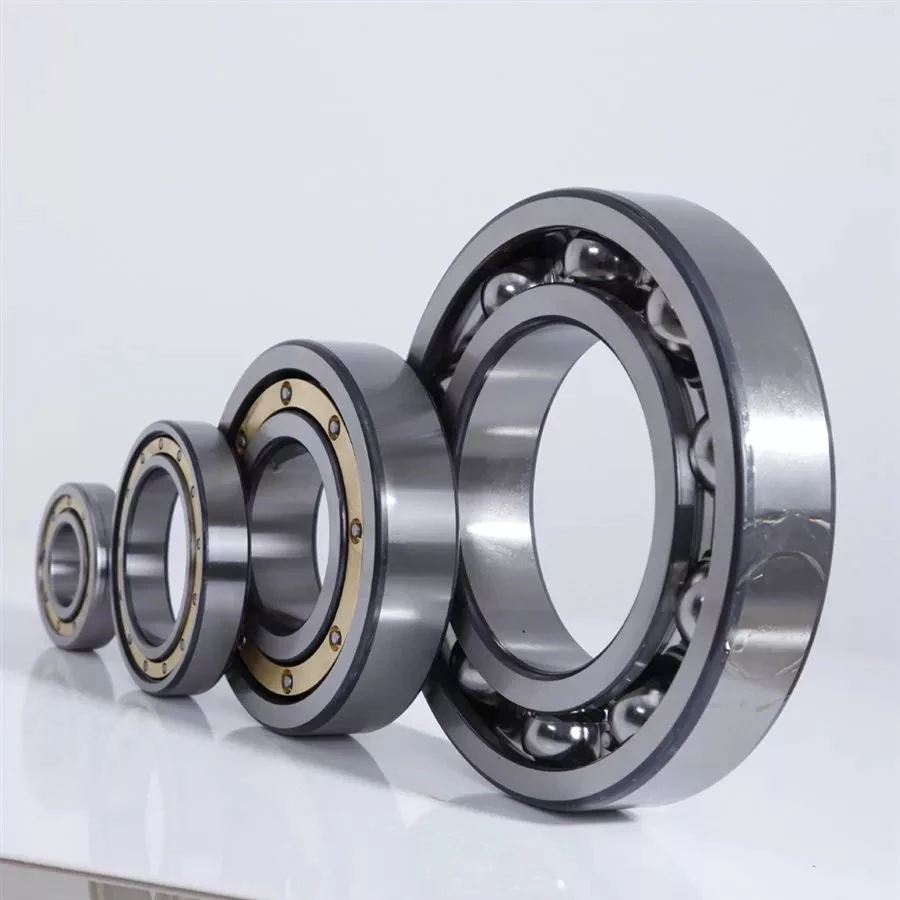
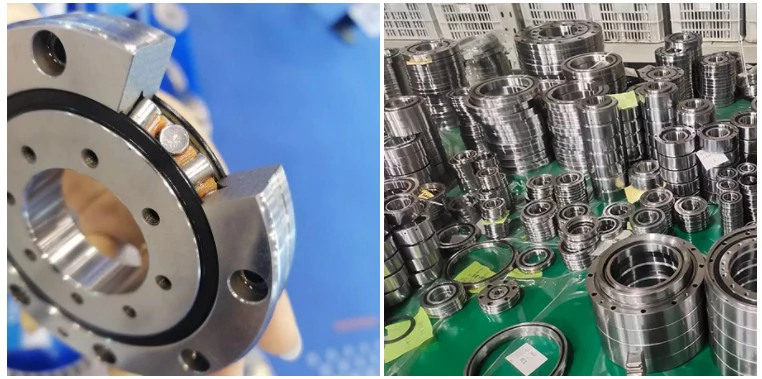
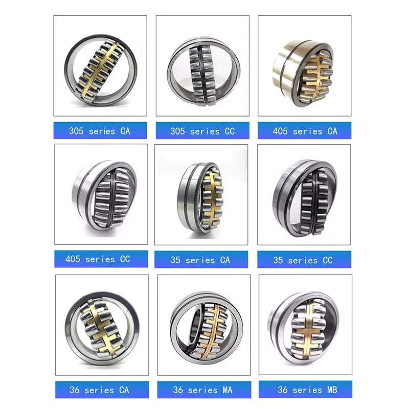
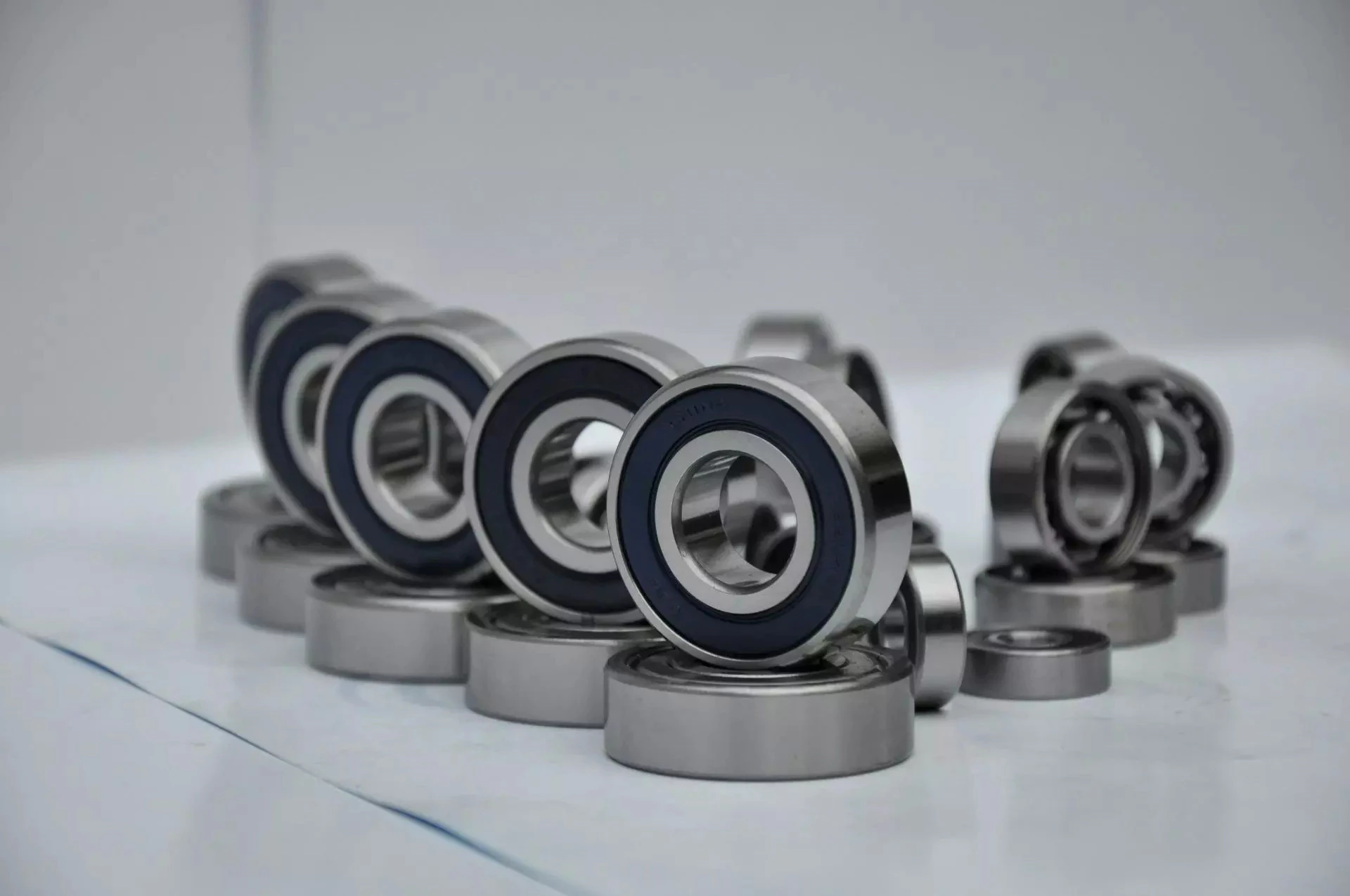
high quality

Screws and Screw Shafts

A screw is a mechanical device that holds objects together. Screws are usually forged or machined. They are also used in screw jacks and press-fitted vises. Their self-locking properties make them a popular choice in many different industries. Here are some of the benefits of screws and how they work. Also read about their self-locking properties. The following information will help you choose the right screw for your application.

Machined screw shaft

A machined screw shaft can be made of various materials, depending on the application. Screw shafts can be made from stainless steel, brass, bronze, titanium, or iron. Most manufacturers use high-precision CNC machines or lathes to manufacture these products. These products come in many sizes and shapes, and they have varying applications. Different materials are used for different sizes and shapes. Here are some examples of what you can use these screws for:
Screws are widely used in many applications. One of the most common uses is in holding objects together. This type of fastener is used in screw jacks, vises, and screw presses. The thread pitch of a screw can vary. Generally, a smaller pitch results in greater mechanical advantage. Hence, a machined screw shaft should be sized appropriately. This ensures that your product will last for a long time.
A machined screw shaft should be compatible with various threading systems. In general, the ASME system is used for threaded parts. The threaded hole occupies most of the shaft. The thread of the bolt occupy either part of the shaft, or the entire one. There are also alternatives to bolts, including riveting, rolling pins, and pinned shafts. These alternatives are not widely used today, but they are useful for certain niche applications.
If you are using a ball screw, you can choose to anneal the screw shaft. To anneal the screw shaft, use a water-soaked rag as a heat barrier. You can choose from 2 different options, depending on your application. One option is to cover the screw shaft with a dust-proof enclosure. Alternatively, you can install a protective heat barrier over the screw shaft. You can also choose to cover the screw shaft with a dust-proof machine.
If you need a smaller size, you can choose a smaller screw. It may be smaller than a quarter of an inch, but it may still be compatible with another part. The smaller ones, however, will often have a corresponding mating part. These parts are typically denominated by their ANSI numerical size designation, which does not indicate threads-per-inch. There is an industry standard for screw sizes that is a little easier to understand.
screwshaft

Ball screw nut

When choosing a Ball screw nut for a screw shaft, it is important to consider the critical speed of the machine. This value excites the natural frequency of a screw and determines how fast it can be turned. In other words, it varies with the screw diameter and unsupported length. It also depends on the screw shaft’s diameter and end fixity. Depending on the application, the nut can be run at a maximum speed of about 80% of its theoretical critical speed.
The inner return of a ball nut is a cross-over deflector that forces the balls to climb over the crest of the screw. In 1 revolution of the screw, a ball will cross over the nut crest to return to the screw. Similarly, the outer circuit is a circular shape. Both flanges have 1 contact point on the ball shaft, and the nut is connected to the screw shaft by a screw.
The accuracy of ball screws depends on several factors, including the manufacturing precision of the ball grooves, the compactness of the assembly, and the set-up precision of the nut. Depending on the application, the lead accuracy of a ball screw nut may vary significantly. To improve lead accuracy, preloading, and lubrication are important. Ewellix ball screw assembly specialists can help you determine the best option for your application.
A ball screw nut should be preloaded prior to installation in order to achieve the expected service life. The smallest amount of preload required can reduce a ball screw’s calculated life by as much as 90 percent. Using a lubricant of a standard grade is recommended. Some lubricants contain additives. Using grease or oil in place of oil can prolong the life of the screw.
A ball screw nut is a type of threaded nut that is used in a number of different applications. It works similar to a ball bearing in that it contains hardened steel balls that move along a series of inclined races. When choosing a ball screw nut, engineers should consider the following factors: speed, life span, mounting, and lubrication. In addition, there are other considerations, such as the environment in which the screw is used.
screwshaft

Self-locking property of screw shaft

A self-locking screw is 1 that is capable of rotating without the use of a lock washer or bolt. This property is dependent on a number of factors, but 1 of them is the pitch angle of the thread. A screw with a small pitch angle is less likely to self-lock, while a large pitch angle is more likely to spontaneously rotate. The limiting angle of a self-locking thread can be calculated by calculating the torque Mkdw at which the screw is first released.
The pitch angle of the screw’s threads and its coefficient of friction determine the self-locking function of the screw. Other factors that affect its self-locking function include environmental conditions, high or low temperature, and vibration. Self-locking screws are often used in single-line applications and are limited by the size of their pitch. Therefore, the self-locking property of the screw shaft depends on the specific application.
The self-locking feature of a screw is an important factor. If a screw is not in a state of motion, it can be a dangerous or unusable machine. The self-locking property of a screw is critical in many applications, from corkscrews to threaded pipe joints. Screws are also used as power linkages, although their use is rarely necessary for high-power operations. In the archimedes’ screw, for example, the blades of the screw rotate around an axis. A screw conveyor uses a rotating helical chamber to move materials. A micrometer uses a precision-calibrated screw to measure length.
Self-locking screws are commonly used in lead screw technology. Their pitch and coefficient of friction are important factors in determining the self-locking property of screws. This property is advantageous in many applications because it eliminates the need for a costly brake. Its self-locking property means that the screw will be secure without requiring a special kind of force or torque. There are many other factors that contribute to the self-locking property of a screw, but this is the most common factor.
Screws with right-hand threads have threads that angle up to the right. The opposite is true for left-hand screws. While turning a screw counter-clockwise will loosen it, a right-handed person will use a right-handed thumb-up to turn it. Similarly, a left-handed person will use their thumb to turn a screw counter-clockwise. And vice versa.
screwshaft

Materials used to manufacture screw shaft

Many materials are commonly used to manufacture screw shafts. The most common are steel, stainless steel, brass, bronze, and titanium. These materials have advantages and disadvantages that make them good candidates for screw production. Some screw types are also made of copper to fight corrosion and ensure durability over time. Other materials include nylon, Teflon, and aluminum. Brass screws are lightweight and have aesthetic appeal. The choice of material for a screw shaft depends on the use it will be made for.
Shafts are typically produced using 3 steps. Screws are manufactured from large coils, wire, or round bar stock. After these are produced, the blanks are cut to the appropriate length and cold headed. This cold working process pressudes features into the screw head. More complicated screw shapes may require 2 heading processes to achieve the desired shape. The process is very precise and accurate, so it is an ideal choice for screw manufacturing.
The type of material used to manufacture a screw shaft is crucial for the function it will serve. The type of material chosen will depend on where the screw is being used. If the screw is for an indoor project, you can opt for a cheaper, low-tech screw. But if the screw is for an outdoor project, you’ll need to use a specific type of screw. This is because outdoor screws will be exposed to humidity and temperature changes. Some screws may even be coated with a protective coating to protect them from the elements.
Screws can also be self-threading and self-tapping. The self-threading or self-tapping screw creates a complementary helix within the material. Other screws are made with a thread which cuts into the material it fastens. Other types of screws create a helical groove on softer material to provide compression. The most common uses of a screw include holding 2 components together.
There are many types of bolts available. Some are more expensive than others, but they are generally more resistant to corrosion. They can also be made from stainless steel or aluminum. But they require high-strength materials. If you’re wondering what screws are, consider this article. There are tons of options available for screw shaft manufacturing. You’ll be surprised how versatile they can be! The choice is yours, and you can be confident that you’ll find the screw shaft that will best fit your application.

high quality high quality

high quality

Helical, Straight-Cut, and Spiral-Bevel Gears

If you are planning to use bevel gears in your machine, you need to understand the differences between Helical, Straight-cut, and Spiral bevel gears. This article will introduce you to these gears, as well as their applications. The article will also discuss the benefits and disadvantages of each type of bevel gear. Once you know the differences, you can choose the right gear for your machine. It is easy to learn about spiral bevel gears.
gear

Spiral bevel gear

Spiral bevel gears play a critical role in the aeronautical transmission system. Their failure can cause devastating accidents. Therefore, accurate detection and fault analysis are necessary for maximizing gear system efficiency. This article will discuss the role of computer aided tooth contact analysis in fault detection and meshing pinion position errors. You can use this method to detect problems in spiral bevel gears. Further, you will learn about its application in other transmission systems.
Spiral bevel gears are designed to mesh the gear teeth more slowly and appropriately. Compared to straight bevel gears, spiral bevel gears are less expensive to manufacture with CNC machining. Spiral bevel gears have a wide range of applications and can even be used to reduce the size of drive shafts and bearings. There are many advantages to spiral bevel gears, but most of them are low-cost.
This type of bevel gear has 3 basic elements: the pinion-gear pair, the load machine, and the output shaft. Each of these is in torsion. Torsional stiffness accounts for the elasticity of the system. Spiral bevel gears are ideal for applications requiring tight backlash monitoring and high-speed operations. CZPT precision machining and adjustable locknuts reduce backlash and allow for precise adjustments. This reduces maintenance and maximizes drive lifespan.
Spiral bevel gears are useful for both high-speed and low-speed applications. High-speed applications require spiral bevel gears for maximum efficiency and speed. They are also ideal for high-speed and high torque, as they can reduce rpm without affecting the vehicle’s speed. They are also great for transferring power between 2 shafts. Spiral bevel gears are widely used in automotive gears, construction equipment, and a variety of industrial applications.

Hypoid bevel gear

The Hypoid bevel gear is similar to the spiral bevel gear but differs in the shape of the teeth and pinion. The smallest ratio would result in the lowest gear reduction. A Hypoid bevel gear is very durable and efficient. It can be used in confined spaces and weighs less than an equivalent cylindrical gear. It is also a popular choice for high-torque applications. The Hypoid bevel gear is a good choice for applications requiring a high level of speed and torque.
The Hypoid bevel gear has multiple teeth that mesh with each other at the same time. Because of this, the gear transmits torque with very little noise. This allows it to transfer a higher torque with less noise. However, it must be noted that a Hypoid bevel gear is usually more expensive than a spiral bevel gear. The cost of a Hypoid bevel gear is higher, but its benefits make it a popular choice for some applications.
A Hypoid bevel gear can be made of several types. They may differ in the number of teeth and their spiral angles. In general, the smaller hypoid gear has a larger pinion than its counterpart. This means that the hypoid gear is more efficient and stronger than its bevel cousin. It can even be nearly silent if it is well lubricated. Once you’ve made the decision to get a Hypoid bevel gear, be sure to read up on its benefits.
Another common application for a Hypoid bevel gear is in automobiles. These gears are commonly used in the differential in automobiles and trucks. The torque transfer characteristics of the Hypoid gear system make it an excellent choice for many applications. In addition to maximizing efficiency, Hypoid gears also provide smoothness and efficiency. While some people may argue that a spiral bevel gear set is better, this is not an ideal solution for most automobile assemblies.
gear

Helical bevel gear

Compared to helical worm gears, helical bevel gears have a small, compact housing and are structurally optimized. They can be mounted in various ways and feature double chamber shaft seals. In addition, the diameter of the shaft and flange of a helical bevel gear is comparable to that of a worm gear. The gear box of a helical bevel gear unit can be as small as 1.6 inches, or as large as 8 cubic feet.
The main characteristic of helical bevel gears is that the teeth on the driver gear are twisted to the left and the helical arc gears have a similar design. In addition to the backlash, the teeth of bevel gears are twisted in a clockwise and counterclockwise direction, depending on the number of helical bevels in the bevel. It is important to note that the tooth contact of a helical bevel gear will be reduced by about 10 to 20 percent if there is no offset between the 2 gears.
In order to create a helical bevel gear, you need to first define the gear and shaft geometry. Once the geometry has been defined, you can proceed to add bosses and perforations. Then, specify the X-Y plane for both the gear and the shaft. Then, the cross section of the gear will be the basis for the solid created after revolution around the X-axis. This way, you can make sure that your gear will be compatible with the pinion.
The development of CNC machines and additive manufacturing processes has greatly simplified the manufacturing process for helical bevel gears. Today, it is possible to design an unlimited number of bevel gear geometry using high-tech machinery. By utilizing the kinematics of a CNC machine center, you can create an unlimited number of gears with the perfect geometry. In the process, you can make both helical bevel gears and spiral bevel gears.

Straight-cut bevel gear

A straight-cut bevel gear is the easiest to manufacture. The first method of manufacturing a straight bevel gear was to use a planer with an indexing head. Later, more efficient methods of manufacturing straight bevel gears were introduced, such as the Revacycle system and the Coniflex system. The latter method is used by CZPT. Here are some of the main benefits of using a straight-cut bevel gear.
A straight-cut bevel gear is defined by its teeth that intersect at the axis of the gear when extended. Straight-cut bevel gears are usually tapered in thickness, with the outer part being larger than the inner portion. Straight-cut bevel gears exhibit instantaneous lines of contact, and are best suited for low-speed, static-load applications. A common application for straight-cut bevel gears is in the differential systems of automobiles.
After being machined, straight-cut bevel gears undergo heat treatment. Case carburizing produces gears with surfaces of 60-63 Rc. Using this method, the pinion is 3 Rc harder than the gear to equalize wear. Flare hardening, flame hardening, and induction hardening methods are rarely used. Finish machining includes turning the outer and inner diameters and special machining processes.
The teeth of a straight-cut bevel gear experience impact and shock loading. Because the teeth of both gears come into contact abruptly, this leads to excessive noise and vibration. The latter limits the speed and power transmission capacity of the gear. On the other hand, a spiral-cut bevel gear experiences gradual but less-destructive loading. It can be used for high-speed applications, but it should be noted that a spiral-cut bevel gear is more complicated to manufacture.
gear

Spur-cut bevel gear

CZPT stocks bevel gears in spiral and straight tooth configurations, in a range of ratios from 1.5 to five. They are also highly remachinable except for the teeth. Spiral bevel gears have a low helix angle and excellent precision properties. CZPT stock bevel gears are manufactured using state-of-the-art technologies and know-how. Compared with spur-cut gears, these have a longer life span.
To determine the strength and durability of a spur-cut bevel gear, you can calculate its MA (mechanical advantage), surface durability (SD), and tooth number (Nb). These values will vary depending on the design and application environment. You can consult the corresponding guides, white papers, and technical specifications to find the best gear for your needs. In addition, CZPT offers a Supplier Discovery Platform that allows you to discover more than 500,000 suppliers.
Another type of spur gear is the double helical gear. It has both left-hand and right-hand helical teeth. This design balances thrust forces and provides extra gear shear area. Helical gears, on the other hand, feature spiral-cut teeth. While both types of gears may generate significant noise and vibration, helical gears are more efficient for high-speed applications. Spur-cut bevel gears may also cause similar effects.
In addition to diametral pitch, the addendum and dedendum have other important properties. The dedendum is the depth of the teeth below the pitch circle. This diameter is the key to determining the center distance between 2 spur gears. The radius of each pitch circle is equal to the entire depth of the spur gear. Spur gears often use the addendum and dedendum angles to describe the teeth.

high quality high quality

China Standard High Quality Diverter Slide Gate Prefabricated Parts for Rice Mill Plant near me factory

Product Description

Low Speed Vertical Bucket Elevator Conveyor Food Grade Bucket Elevator for Rice
Rice mill plant Chain Conveyor and vertical bucket elevator


Low Speed SE Elevator Features:
SE series bucket elevator for rice has attacrtive and novel appearance, small sace requirement, large conveying capacity, low energy consumption, low rate of rice broken, less backflow characterisitcs. It is mainly applied in vertical lifiting for a variety of granular material in grain, oil, food and feed industries. Elevation to avoid broken.Auto-tightening on bucket belts.
 

Model Model

SE-6S

 SE-7S

 SE-8S

 SE – 10S

Capacity ( t / h )

 5-6

 9-11

 14-16

 25-30

Bucket belt linear speed (m/s)

 0.8~1.8

 0.8~1.8

 0.8~1.8

 0.8 ~ 1.8


TDTG High Speed Elevator Features:
TDTG series high speed elevator is a new generation product that researched and developed by digestion and absorption of foreign similar advanced technology. It is applicable to all kinds of granular and powder materials vertical conveying and can be widely used in CZPT and oil, flour, feed and chemical industries. 
 

Model Bucket Model Capacity (T/H) Linear Speed Height Model Bucket Model Capacity (T/H) Linear Speed Height

Link Chain Coveyor Features:
1.Suitable for all kinds of streamlined production of bulk and package ‘S logistics transportation.
2.With good stable performance safe dependability and easy operation.
3.Transportation capability is strong, transportation distance,
4.low energy consumption, and low cost of usage.
5. It is convenient to operate procedure control and automation, and also can go and down transportation.

Model Chain Distance Linear Speed Capacity (T/H) Conveying length

Factory Products Glance: 

Others Products can also manufacturing — Prefabricated Parts + Diverter 

Project Cases: 


How to Replace a Bearing

If you want to select a bearing for a specific application, you should know a few basics. This article will give you an overview of ball, angular contact, and sliding-contact bearings. You can choose a bearing according to the application based on the characteristics of its material and preload. If you are not sure how to choose a bearing, try experimenting with it. The next step is to understand the Z-axis, which is the axes along which the bearing moves.

Z axis

When it comes to replacing your Z axis bearing, there are several things you must know. First, you need to make sure that the bearings are seated correctly. Then, you should check the tension and rotation of each one. To ensure that both bearings are equally tensioned, you should flex the Core to the desired angle. This will keep the Z axis perpendicular to the work surface. To do this, first remove the Z axis bearing from its housing and insert it into the Z axis motor plate. Next, insert the flanged bearing into the Z axis motor plate and secure it with 2 M5x8mm button head cap screws.
Make sure that the bearing plate and the Z Coupler part are flush and have equal spacing. The spacing between the 2 parts is important, as too much spacing will cause the leadscrew to become tight. The screws should be very loose, with the exception of the ones that engage the nylocks. After installing the bearing, the next step is to start the Z axis. Once this is done, you’ll be able to move it around with a stepper.

Angular contact

bearing
Ball bearings are made with angular contacts that result in an angle between the bearing’s races. While the axial load moves in 1 direction through the bearing, the radial load follows a curved path, tending to separate the races axially. In order to minimize this frictional effect, angular contact bearings are designed with the same contact angle on the inner and outer races. The contact angle must be chosen to match the relative proportions of the axial and radial loads. Generally, a larger contact angle supports a higher axial load, while reducing radial load.
Ball bearings are the most common type of angular contact bearings. Angular contact ball bearings are used in many applications, but their primary purpose is in the spindle of a machine tool. These bearings are suitable for high-speed, precision rotation. Their radial load capacity is proportional to the angular contact angle, so larger contact angles tend to enlarge with speed. Angular contact ball bearings are available in single and double-row configurations.
Angular contact ball bearings are a great choice for applications that involve axial loads and complex shapes. These bearings have raceways on the inner and outer rings and mutual displacement along the axial axis. Their axial load bearing capacity increases as the contact Angle a rises. Angular contact ball bearings can withstand loads up to 5 times their initial weight! For those who are new to bearings, there are many resources online dedicated to the subject.
Despite their complexity, angular contact ball bearings are highly versatile and can be used in a wide range of applications. Their angular contact enables them to withstand moderate radial and thrust loads. Unlike some other bearings, angular contact ball bearings can be positioned in tandem to reduce friction. They also feature a preload mechanism that removes excess play while the bearing is in use.
Angular contact ball bearings are made with different lubricants and cage materials. Standard cages for angular contact ball bearings correspond to Table 1. Some are machined synthetic resins while others are molded polyamide. These cage materials are used to further enhance the bearing’s axial load capacity. Further, angular contact ball bearings can withstand high speeds and radial loads. Compared to radial contact ball bearings, angular contact ball bearings offer the greatest flexibility.

Ball bearings

bearing
Ball bearings are circular structures with 2 separate rings. The smaller ring is mounted on a shaft. The inner ring has a groove on the outer diameter that acts as a path for the balls. Both the inner and outer ring surfaces are finished with very high precision and tolerance. The outer ring is the circular structure with the rolling elements. These elements can take many forms. The inner and outer races are generally made of steel or ceramic.
Silicon nitride ceramic balls have good corrosion resistance and lightweight, but are more expensive than aluminum oxide balls. They also exhibit an insulating effect and are self-lubricating. Silicon nitride is also suitable for high-temperature environments. However, this type of material has the disadvantage of wearing out rapidly and is prone to cracking and shattering, as is the case with bearing steel and glass. It’s also less resistant to heat than aluminum oxide, so it’s best to buy aluminum nitride or ceramic ball bearings for applications that are subjected to extremely high temperatures.
Another type of ball bearings is the thrust bearing. It has a special design that accommodates forces in both axial and radial directions. It is also called a bidirectional bearing because its races are side-by-side. Axial ball bearings use a side-by-side design, and axial balls are used when the loads are transmitted through the wheel. However, they have poor axial support and are prone to separating during heavy radial loads.
The basic idea behind ball bearings is to reduce friction. By reducing friction, you’ll be able to transfer more energy, have less erosion, and improve the life of your machine. With today’s advances in technology, ball bearings can perform better than ever before. From iron to steel to plastics, the materials used in bearings have improved dramatically. Bearings may also incorporate an electromagnetic field. So, it’s best to select the right 1 for your machine.
The life expectancy of ball bearings depends on many factors, including the operating speed, lubrication, and temperature. A single million-rpm ball bearing can handle between 1 and 5 million rotations. As long as its surface contact area is as small as possible, it’s likely to be serviceable for at least 1 million rotations. However, the average lifespan of ball bearings depends on the application and operating conditions. Fortunately, most bearings can handle a million or more rotations before they start showing signs of fatigue.

Sliding-contact bearings

bearing
The basic principle behind sliding-contact bearings is that 2 surfaces move in contact with 1 another. This type of bearing works best in situations where the surfaces are made of dissimilar materials. For instance, a steel shaft shouldn’t run in a bronze-lined bore, or vice versa. Instead, 1 element should be harder than the other, since wear would concentrate in that area. In addition, abrasive particles tend to force themselves into the softer surface, causing a groove to wear in that part.
Sliding-contact bearings have low coefficients of friction and are commonly used in low-speed applications. Unlike ball and roller bearings, sliding contact bearings have to be lubricated on both sides of the contacting surfaces to minimize wear and tear. Sliding-contact bearings generally are made of ceramics, brass, and polymers. Because of their lower friction, they are less accurate than rolling-element bearings.
Sliding-contact bearings are also known as plain or sleeve bearings. They have a sliding motion between their 2 surfaces, which is reduced by lubrication. This type of bearing is often used in rotary applications and as guide mechanisms. In addition to providing sliding action, sliding-contact bearings are self-lubricating and have high load-carrying capacities. They are typically available in 2 different types: plain bearings and thrust bearings.
Sliding-contact linear bearing systems consist of a moving structure (called the carriage or slide) and the surfaces on which the 2 elements slide. The surfaces on which the bearing and journal move are called rails, ways, or guides. A bore hole is a complex geometry, and a minimum oil film thickness h0 is usually used at the line of centers. It is possible to have a sliding-contact bearing in a pillow block.
Because these bearings are porous, they can absorb 15 to 30% of the lubrication oil. This material is commonly used in automobile and machine tools. Many non-metallic materials are used as bearings. One example is rubber, which offers excellent shock absorbency and embeddability. While rubber has poor strength and thermal conductivity, it is commonly used in deep-well pumps and centrifugal pumps. This material has high impact strength, but is not as rigid as steel.

China Standard High Quality Diverter Slide Gate Prefabricated Parts for Rice Mill Plant     near me factory China Standard High Quality Diverter Slide Gate Prefabricated Parts for Rice Mill Plant     near me factory

China OEM Coffee Maker Base Soybean Milk Machine Spare Parts near me factory

Product Description

Our products show 
 

Workcraft  CNC punching machining & stamping, laser cutting, bending, threading, welding, deep drawing, polishing, tapping, riveting, final assembly. 
Materials we can process on any steel sheet, copper, aluminum, brass, iron
Surface Treatment Brushing, sand blastig, electroplating (zinc  , nickel , chrome  coating)    Powder coating, polishing(mirror polishing, electrolytic polishing), 
Tolerance the best can be +/-0.01mm
Packing carton, pallet
Application electrics , Vehicles,  Construction Machineries Engineering Machineries, Food Machineries, 
Quality Control we have testing tooling or can apply different tests from the 3rd party
Technical File Formats Solidworks, PRO/E, Auto CAD, PDF, Step, Stp, Dwg, Drw, Prt, etc
Inspections to work  IQC, PQC, FQC, OQA

Technology capabilities
We work as per AUTOCAD, PRO-E, Solidworks , UG. 3D max WORKS and other 2D & 3D softwares. can  design,develop,produce and deliver your PO according to your drawings, samples or just an idea. control of non-standard products and OEM  products.

Quality Control
1.  IQC,   incoming quality control
2.Check  the details before the production line operated
3.IPQC, have full inspection and routing inspection during mass production 
4.FQC, check  the goods after they are finished 
5.OQC,check  the goods  before the delivery


FAQ

1.Is CZPT a  manufacturer ?

A: We are a manufacturer, the business owner has 2 factories producing springs, machining part, stamping parts

2. When is the delivery time?

A: 10 and 15 days , 1 month in the CZPT seasons

3. What is the MOQ?

For the initial order , any quantity ok. For the mass production order, 10000 pcs better.

4. What’s your payment method?

 : T/T, L/C, Western Unions,  

5. How can we confirm the samples?

Free samples are offered,  

Axle Spindle Types and Features

The axle spindle is an integral part of your vehicle’s suspension. There are several different types and features, including mounting methods, bearings, and functions. Read on for some basic information on axle spindles. The next part of the article will cover how to choose the correct axle spindle for your vehicle. This article will also discuss the different types of spindles available, including the differences between the rear and front bearings.
Driveshaft

Features

The improved axle spindle nut assembly is capable of providing additional performance benefits, including increased tire life and reduced seal failure. Its keyway features and radially inwardly extending teeth allow nut adjustment to be accomplished with precision. The invention further provides a unique, multi-piece locking mechanism that minimizes leakage and torque transfer. Its principles and features are detailed in the appended claims. For example, the improved axle spindle nut assembly is designed for use in vehicles that are equipped with a steering system.
The axle spindle nut assembly includes a nut 252 with threads 256 on its inner periphery. The axle spindle 50 also features threads 198 on its outer periphery. The nut is threaded onto the outboard end of the axle spindle 50 until it contacts the inboard surface of the axle spacer 26. In the assembled state, a bearing spacer 58 is also present on the axle spindle.
The axle spindle nut assembly can reduce axial end play between the wheel end assembly 52 and the axle spindle 50. It can be tightened to an extreme torque level, but if the thread faces separate, it will undercompress the bearing cone and spacer group. To minimize these disadvantages, the axle spindle nut assembly is a critical component of a wheel-end assembly. There are several types of axle spindle nuts.
The third embodiment of the axle spindle nut assembly 300 comprises an inner washer 202, an outer washer 310, and at least 1 screw 320. The axle spindle nut assembly 300 secures and preloads bearing cones 55, 57. Unlike the first embodiment, the axle spindle nut assembly 300 uses the inner washer 202, which is optional in the third embodiment. The inner washer 202 and outer washer 310 are similar to those of the first embodiment.

Functions

An axle spindle is 1 of the most important components of a vehicle’s suspension system. The spindle retains the position of bearings and a spacer in an axle by providing clamp force. The inner nut of an axle spindle should be properly torqued to ensure a secure fit. A spindle nut is also responsible for compressing bearings and spacers. If any of these components are missing, the spindle will not work properly.
An axle spindle is used in rear wheel drive cars. It carries the weight of the vehicle on the axle casing and transfers the torque from the differential to the wheels. The axle spindle and hub are secured on the spindle by large nuts. The axle spindle is a vital component of rear wheel drive vehicles. Hence, it is essential to understand the functions of axle spindle. These components are responsible for the smooth operation of a vehicle’s suspension system.
Axle spindles can be mounted in 3 ways: in the typical axle assembly, the spindles are bolted onto the ends of the tubular axle, and the axle is suspended by springs. Short stub-axle mounting uses a torsion beam that flexes to provide a smooth ride. A second washer is used to prevent excessive rotation of the axle spindle.
Apart from being a crucial component of the suspension system, the spindles of the wheels are responsible for guiding the vehicle in a straight line. They are connected to the steering axis and are used in different types of suspension systems. European cars use a MacPherson Strut suspension system in which the spindle is connected to the arms in the front and rear of the suspension frame. The MacPherson strut allows the shock absorber housing to turn the wheel.
Driveshaft

Methods of mounting

Various methods of mounting axle spindle are available. In general, these methods involve forming a tubular blank of uniform cross section and thickness, and receiving the bearing assembly against it. The spindle is then secured using a collar, which also serves as a bearing stop. In some cases, additional features are used to provide greater security. Some of these features may not be suitable for all applications. But they are generally suitable.
Axle spindle forming is usually done by progressive steps using hollow punches. The metallic body of the punch has an inner work surface, which receives the axle blank. A mandrel is fixed within the work opening of the punch. The punch body’s work surface forges the spindle about the mandrel. The punch has 2 ends, a closed and an open one.
A wheeled vehicle axle assembly (10) includes a cylindrical housing member (12 a) and a plurality of spindle mounting flanges (30) secured on the housing member. The spindles (16) are firmly attached to the housing member by means of coupling members. The coupling members are configured to distribute the bending loads imposed on the spindle by the axle. It is important to note that the coupling members can be either threaded or screwed.
Traditionally, axle spindles were made from tubular blanks of irregular thickness. This method allowed for a gradual reduction in diameter and eliminated the need for extra metal within the spindle. Similarly, axles made by cold forming eliminate the need for additional metal in the spindle. In this way, the overall cost of manufacture is also reduced. The material used for manufacturing axles also determines the size and shape of the final product.
Driveshaft

Bearings

A nut 16 is used to retain the wheel bearings on axle spindle 12. The nut comprises several parts. The first portion includes a plurality of threads and a deformable second portion. The nut may be disposed on the inboard or outboard end of the axle spindle. This type of nut is typically secured to the axle spindle by a retaining nut.
The bearings are installed in the spindle to allow the wheel hub to rotate. While bearings are greased, they can dry out over time. Consequently, you may hear a loud clicking sound when turning your vehicle. Alternatively, you may notice grease on the edges of your tires. Bearing failure can cause severe damage to your axle spindle. If you notice any of these symptoms, you may need to replace the bearings on your axle spindle. Fortunately, you can purchase the necessary bearing parts at O’Reilly Auto Parts.
There are 3 ways to mount an axle spindle. A typical axle assembly has the spindles bolted to the ends of the tubular axle. A torsion beam is also used to mount the spindles on the axle. This torsion beam acts like a spring to help make the ride smooth and bump-free. Lastly, the axle spindle is sometimes mounted as a bolt-on component.

Cost

If your axle spindle has been damaged, you may need to have it replaced. This part of the axle is relatively easy to replace, but you need to know how to do it correctly. To replace your axle spindle, you must first remove the damaged one. To do this, a technician will cut the weld. They will then thread the new 1 into the axle tube and torque it to specification. After that, they will weld the new axle spindle into place.
When you are thinking about the cost of an axle spindle replacement, you must first determine if it is worth it for your vehicle. It is generally a good idea to replace the spindle only if it is causing damage to your vehicle. You can also replace your axle housing if it is deteriorating. If you do not replace the spindle, you can risk damaging the axle housing. To save money, you can consider using a repair kit.
You can also purchase an axle nut socket set. Most wrenches have an adjusting socket for this purpose. The socket set should be suitable for most vehicle types. Axle spindle replacement costs around $500 to $600 before tax. However, you should be aware that these costs vary widely based on the type of vehicle you have. The parts can cost between $430 and $480, and the labor can cost anywhere from $50 to 70.

China OEM Coffee Maker Base Soybean Milk Machine Spare Parts     near me factory China OEM Coffee Maker Base Soybean Milk Machine Spare Parts     near me factory

China Hot selling Supplier Price Auto Parts Warning Red Orange Green with Reflective Collars PVC Plastic Reflective Traffic Cone/Cono for High Road with Great quality

Product Description

                                             PVC Traffic Cone

The PVC cone could be twisted and pressed in 180 degrees. It could also reinstate when you make
its top touch the floor, with high flexibility against the runover and impact of the cars. Because of good
weather resistance, it won’t deform in high tempreture 65°C and craze in low tempreture -30°C. Highly
reflective, good warning effects at both day and night, anti-UV, aging resistance and durable. This traffic
cone has a wide body profile for stability. Drive for the road separating the role of the warning; Coupled
with the role of the lattice better

Product Specifications

Model No

Height

Weight

Base Size

Standand Reflex

CO30CM

300mm

0.4Kg

210mm*210mm

150mm Reflex

CO45CM

450mm

1Kg

280mm*280mm

150mm Reflex

CO70CM

700mm

1.75Kg

340mm*340mm

150mm+100mm Reflex

CO90CM

900mm

3.4Kg

360mm*360mm

150mm+100mm Reflex


Name

PVC Cone

HS CODE

39269 0571 0

Material

PVC

Color

Red/Orange

Application

Road, Road Construction, Parking, Car, Railway.

Package

Woven Bag/Pallet

Features of Traffic Cones

1. Favorable flexbility and stand press of cars;
2. Sunproof, waterproof, heat-resistant, cold-resistant, non-rimous, color fast, etc;
3. Reflect dazzing light and make the drivers see clearly;
4. Applicable to parking lot, road, gas station, highway, etc;

Products & Packing


Related Products


Company Profile


FAQ

Q:Can I have samples?
A:We are honored to offer you samples. 

Q:Can I add my logo?
A:Yes, OEM and ODM are available for us.

Q:What’s your delivery time?
A:ormally need 25-35 days to produce an order after receiving the deposit.
But the exact delivery time will be different depend on your quantity.

Q:Can I mix different models in 1 order?
A:Of course, but each item’s quantity need to reach our MOQ.

Q:What’s the payment you accept ?
A:T/T, Western union, Paypal.

Competitive Price Road Safety Orange Eye-Catching Reflective 30/45/70/90cm PVC Plastic Cone/Cono for Car

Types of Ball Bearings

In their most basic form, Ball Bearings have 1 common feature – they are made of steel. The majority of these bearings are made of 52100 steel, which has 1 percent chromium and 1 percent carbon. The steel can be hardened by heat trea
tment. 440C stainless steel is used for rusting problems. A cage around the ball balls is traditionally made from thin steel. However, some bearings use molded plastic cages to save money and friction.
bearing

Single-row designs

Steel linear translation stages often use single-row designs for ball bearings. These types of bearings provide smooth linear travel and can withstand high loads. The material steel has a high modulus of elasticity and a high stiffness, as well as a lower thermal expansion than aluminum. For these reasons, steel is the material of choice for a ball bearing in a typical user environment. Single-row designs for ball bearings are also suitable for applications in humid or corrosive environments.
Single-row designs for ball bearings are available in a variety of sizes and are axially adjustable. They have a high radial capacity, but require relatively little space. Single-row deep groove ball bearings with snap rings are STN 02 4605 or R47, respectively. Bearings with snap rings are identified by a suffix such as NR. They may not have seals or shields installed.
These single-row angular contact ball bearings are capable of supporting axial and radial loads. In a two-raceway arrangement, the radial load on bearing A causes a radial load to act on bearing B. Both axial and radial forces are transmitted between single-row angular contact ball bearings, and the resulting internal force must be taken into account to calculate equivalent dynamic bearing loads P.
Single-row deep groove ball bearings are the most common type of ball bearings. These bearings are designed with only 1 row of rolling elements. The single-row design is simple and durable, which makes it ideal for high-speed applications. Single-row designs for ball bearings are also available in various bore sizes. They can also come in a variety of shapes and are non-separable. If you need a high-speed bearing, you may want to opt for a double-row design.
In addition to single-row designs for ball bearings, you can choose ceramic or steel ball bearings. Ceramic balls are considerably harder than steel balls, but they are not as hard as steel. Hence, ceramic bearings are stiffer than steel ball bearings, resulting in increased stress on the outer race groove and lower load capacity. This is a great benefit for those who need the bearings to be lightweight and strong.
The difference between single-row and double-row designs is in the way that the inner and outer ring are installed. A single-row design places the inner ring in an eccentric position relative to the outer ring. The 2 rings are in contact at 1 point, which causes a large gap in the bearing. The balls are then inserted through the gap. As a result, the balls are evenly distributed throughout the bearing, which forces the inner and outer rings to become concentric.
Deep-groove ball bearings are 1 of the most popular types of ball bearings. They are available in different designs, including snap-ring, seal and shield arrangements. The race diameter of a deep-groove ball bearing is close to the ball’s diameter. These types of bearings are suited for heavy loads, and their axial and radial support are excellent. Their main drawback is that the contact angle cannot be adjusted to accommodate a wide range of relative loads.
bearing

Ceramic hybrid ball bearings

Hybrid ball bearings with ceramic balls have numerous advantages. They feature improved kinematic behavior and require less lubrication. Consequently, they can reduce operating costs. Additionally, their low thermal expansion coefficient allows for smaller changes in contact angle and preload variations, and they can retain tolerances. Furthermore, ceramic hybrid ball bearings have significantly increased life spans compared to conventional steel-steel ball bearings, with up to 10 times the lifespan.
Although ceramic bearings can be used in automotive applications, many people believe that they’re a poor choice for bicycle hubs. They don’t reduce weight and only work well in high-rpm environments. As a result, many cyclists don’t even bother with ceramic-based bearings. However, both Paul Lew and Alan are of the opinion that ceramic bearings are best suited for industrial or medical equipment applications. Furthermore, Paul and Alan believe that they are ideal for high-altitude drone motors.
Another advantage of ceramic hybrid ball bearings is that they use less friction than conventional steel-based balls. They are also more durable, requiring less lubrication than steel-based bearings. Furthermore, the lower friction and rolling resistance associated with ceramic-based ball bearings means that they can last 10 times longer than steel-based bearings. A ceramic-based hybrid ball bearing can be used for applications where speed and lubrication are critical.
Ceramic hybrid ball bearings feature both steel and silicon nitride balls. Silicon nitride balls have 50% more modulus of elasticity than steel balls and can improve accuracy and precision. Ceramic balls also have a smoother surface finish than steel balls, which reduces vibration and spindle deflection. These benefits result in increased speed and improved production quality. In addition to this, ceramic balls can also reduce the operating temperature, enhancing the work environment.
Hybrid bearings are a popular alternative to steel bearings. They have some benefits over traditional steel bearings, and are becoming a popular choice for engineered applications. Hybrid bearings are ideal for high speed machines. The material used to manufacture ceramic balls is a high-quality alloy, and is comparatively inexpensive. But you must understand that lubrication is still necessary for hybrid bearings. If you are not careful, you may end up wasting money.
These ball bearings can be used in many industries and applications, and they are widely compatible with most metals. The main advantage of hybrid ball bearings is that they are very durable. While steel balls tend to corrode and wear out, ceramic ball bearings can withstand these conditions while minimizing maintenance and replacement costs. The benefits of hybrid ball bearings are clear. So, consider switching to these newer types of ball bearings.
bearing

Self-aligning ball bearings

Self-aligning ball bearings are a good choice for many applications. They are a great alternative to traditional ball bearings, and they are ideal for rotating applications in which the shaft must move in several directions. They are also ideal for use in rotating parts where a tight tolerance is necessary. You can choose between 2 types: plain and flex shaft. Read on to find out which 1 will suit your needs.
Self-aligning ball bearings are designed with a higher axial load carrying capacity than single-row radial deep groove ball bearings. The amount of axial load carrying capacity is dependent upon the pressure angle. These bearings have a hollow raceway in the outer ring that allows the inner ring to pivot without friction. They are often used for high-speed applications. Because of their design, they are highly accurate.
Self-aligning ball bearings are radial bearings that feature 2 rows of balls in a spherical outer ring. They also feature 2 deep uninterrupted raceway grooves in the inner ring. Their unique features make them an excellent choice for applications where shaft deflection is a significant factor. Despite their small size, they have a high level of precision and can withstand heavy loads.
Self-aligning ball bearings can compensate for misalignment in shaft applications. The inner ring and ball assembly are positioned inside an outer ring containing a curved raceway. This spherical design allows the balls and cage to deflect and re-align around the bearing center. These bearings are also ideal for applications where shaft deflection is significant, such as in simple woodworking machinery.
Another type of self-aligning ball bearing uses a common concave outer race. Both balls and outer races automatically compensate for angular misalignment caused by machining, assembly, and deflections. Compared to spherical rollers, they have lower frictional losses than their spherical counterparts. Self-alignment ball bearings also have lower vibration levels compared to other types of bearings.
Self-aligning ball bearings operate in misaligned applications because their spherical outer raceway can accommodate misalignment. This design allows them to work in applications where shaft deflection or housing deformation is common. They are therefore more suitable for low to medium-sized loads. The only real drawback to self-aligning ball bearings is their price. If you need to purchase a self-aligning ball bearing for your next project, you can expect to pay around $1500.

China Hot selling Supplier Price Auto Parts Warning Red Orange Green with Reflective Collars PVC Plastic Reflective Traffic Cone/Cono for High Road     with Great qualityChina Hot selling Supplier Price Auto Parts Warning Red Orange Green with Reflective Collars PVC Plastic Reflective Traffic Cone/Cono for High Road     with Great quality

factory

Standard Length Splined Shafts

Standard Length Splined Shafts are made from Mild Steel and are perfect for most repair jobs, custom machinery building, and many other applications. All stock splined shafts are 2-3/4 inches in length, and full splines are available in any length, with additional materials and working lengths available upon request and quotation. CZPT Manufacturing Company is proud to offer these standard length shafts.
splineshaft

Disc brake mounting interfaces that are splined

There are 2 common disc brake mounting interfaces, splined and center lock. Disc brakes with splined interfaces are more common. They are usually easier to install. The center lock system requires a tool to remove the locking ring on the disc hub. Six-bolt rotors are easier to install and require only 6 bolts. The center lock system is commonly used with performance road bikes.
Post mount disc brakes require a post mount adapter, while flat mount disc brakes do not. Post mount adapters are more common and are used for carbon mountain bikes, while flat mount interfaces are becoming the norm on road and gravel bikes. All disc brake adapters are adjustable for rotor size, though. Road bikes usually use 160mm rotors while mountain bikes use rotors that are 180mm or 200mm.
splineshaft

Disc brake mounting interfaces that are helical splined

A helical splined disc brake mounting interface is designed with a splined connection between the hub and brake disc. This splined connection allows for a relatively large amount of radial and rotational displacement between the disc and hub. A loosely splined interface can cause a rattling noise due to the movement of the disc in relation to the hub.
The splines on the brake disc and hub are connected via an air gap. The air gap helps reduce heat conduction from the brake disc to the hub. The present invention addresses problems of noise, heat, and retraction of brake discs at the release of the brake. It also addresses issues with skewing and dragging. If you’re unsure whether this type of mounting interface is right for you, consult your mechanic.
Disc brake mounting interfaces that are helix-splined may be used in conjunction with other components of a wheel. They are particularly useful in disc brake mounting interfaces for hub-to-hub assemblies. The spacer elements, which are preferably located circumferentially, provide substantially the same function no matter how the brake disc rotates. Preferably, 3 spacer elements are located around the brake disc. Each of these spacer elements has equal clearance between the splines of the brake disc and the hub.
Spacer elements 6 include a helical spring portion 6.1 and extensions in tangential directions that terminate in hooks 6.4. These hooks abut against the brake disc 1 in both directions. The helical spring portion 5.1 and 6.1 have stiffness enough to absorb radial impacts. The spacer elements are arranged around the circumference of the intermeshing zone.
A helical splined disc mount includes a stabilizing element formed as a helical spring. The helical spring extends to the disc’s splines and teeth. The ends of the extension extend in opposite directions, while brackets at each end engage with the disc’s splines and teeth. This stabilizing element is positioned axially over the disc’s width.
Helical splined disc brake mounting interfaces are popular in bicycles and road bicycles. They’re a reliable, durable way to mount your brakes. Splines are widely used in aerospace, and have a higher fatigue life and reliability. The interfaces between the splined disc brake and BB spindle are made from aluminum and acetate.
As the splined hub mounts the disc in a helical fashion, the spring wire and disc 2 will be positioned in close contact. As the spring wire contacts the disc, it creates friction forces that are evenly distributed throughout the disc. This allows for a wide range of axial motion. Disc brake mounting interfaces that are helical splined have higher strength and stiffness than their counterparts.
Disc brake mounting interfaces that are helically splined can have a wide range of splined surfaces. The splined surfaces are the most common type of disc brake mounting interfaces. They are typically made of stainless steel or aluminum and can be used for a variety of applications. However, a splined disc mount will not support a disc with an oversized brake caliper.

factory factory

China Hot selling Jushixin Made in China 460HP CZPT CZPT A7, Euro3, Euro4 Tractor/Car Parts with Hot selling

Product Description

Jushixin Made in China 460HP CZPT CZPT A7, Euro3, Euro4 Tractor/Car Parts
 

Product Description


   It’s suitable for towing all kinds semi trailer which is used in Logistics business, construction site and Mining area.

   This model is the proven product, which features reliable structure, great loading capacity, excellent power from 375HP, reliable performance. This model can meet the requirements of different road conditions. This model can satisfy your need of long distance highway transportation.

Product Parameters


Detailed Photos


Related Products

Company Profile

Packaging & Shipping


What Is a Pulley?

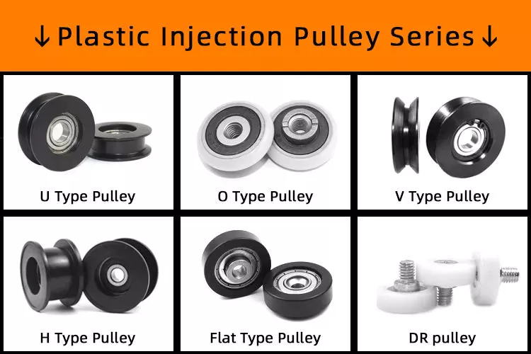
The pulley is a wheel mounted on a shaft or axle. Its purpose is to support the movement of a cable that is taut. This cable transfers power to a shaft. However, there are certain safety precautions that you should follow when using a pulley. Read on to learn more! Listed below are common uses and their main parts. Listed below are some of the benefits of using a pulley.
pulley

Common uses of a pulley

A pulley is a common mechanical device used to increase the force needed to lift a heavy object. Most commonly, these devices are used in construction equipment. These machines use high-10sion ropes to transfer heavy objects from 1 floor to another. Other common uses of a pulley include buckets and flagpoles. These devices are extremely useful in a wide range of applications. To learn more about the common uses of pulleys, keep reading.
A pulley is a wheel with grooves for holding rope. Its purpose is to change the direction and point at which a pulling force acts. It is usually used in sets to reduce the amount of force needed to lift a load, but the work involved is similar. Pulleys are also used in rock climbing devices. For many applications, a pulley is a vital part of construction.
The most common use of a pulley involves hoisting and lowering a flag. Other examples include clotheslines, bird feeders, and escalators. Pulleys are also commonly used on oil derricks. Many other common applications include hoisting and lowering garage doors. Pulley systems are also used in engines and cranes. For more information, check out our interactive pulley diagram!
Pulleys can also be used to lower total work required for a task. In many cases, a pulley will consist of 2 parts: the pulley hub and the shaft pulley. The hub clamps the shaft pulley, while the pulley itself is connected to the motor or other device. If you’re looking for a pulley, it’s important to learn how it works.
The most common uses for a pulley involve lifting heavy objects, and the mechanism used to lift them is known as a pulley. A pulley is an industrial device that uses 2 wheels to reduce the force needed to lift a weight. The pulley reduces this force by half by allowing the user to pull on the rope 4 times as far. The pulley also allows for a smaller lifting distance.

Main parts of a pulley

A pulley consists of the main element of a system. This is typically a cable, rope, belt, or chain. There are 2 basic types of pulleys – a Driver Pulley and a Follower Pulley. Pulleys are available in small and large sizes. The periphery part of the pulley is called the Face, and the protruding middle part is called the Crown. A pulley’s face can be round, rectangular, or even “V” shaped.
The first pulley was created by the Greek mathematician Archimedes in the third century BCE. These simple machines are made of a rope, an axle, and a wheel. The pulley’s end is attached to a person, object, or motor. These machines can be used in various tasks to lift heavy objects. The pulley is a great mechanical advantage for any lifter.
The ideal mechanical advantage of a pulley is defined by the number of rope segments that pull an object. The higher the number of loops on the rope, the higher the mechanical advantage. The greater the mechanical advantage, the less force is required to move the object. Likewise, the greater the distance the rope traverses, the higher the mechanical advantage of a pulley. There are several different types of pulley, depending on their combination of rope, wheel, and rope.
The basic components of a pulley are the face and hub, and the rope is threaded into the center of the pulley. The pulley is usually made of a rope and can be used to lift heavy weights. It can also be used to apply great force in any direction. Step pulleys have multiple faces, which are fixed in sequence. They can also increase the speed of the driven pulley.
A pulley is a simple machine consisting of a wheel, rope, or chain. These parts are crucial for making moving and lifting easier. Because they change the direction and magnitude of force, they can be a useful tool. Some pulleys even change direction. You can learn more about the pulley by downloading this resource today. The resources are designed to support the new 9-1 GCSEs in Design & Technology and Engineering.
pulley

Mechanical advantage

Pulleys have been used to move heavy objects for centuries. When 2 rope sections are used, the weight of a 100kg mass can be moved with only 500 newtons of force. Adding an extra pulley increases the mechanical advantage. If the pulley has 2 wheels, the distance between the rope sections and the wheel grooves is only half the distance, but the mechanical advantage still applies. Adding another pulley increases the mechanical advantage, but can be risky.
Mechanical advantage is the ratio of force used versus force applied. The calculations are made under the assumption that the ropes and weights do not elongate or lose energy due to friction. If the weights are very light, the mechanical advantage is greater than that in the real world. To calculate the mechanical advantage, the weight of the load to be lifted must be the same as the weight of the person using the pulley.
A single moveable pulley has a mechanical advantage of two. The weight passes around the pulley, and 1 end of the rope is attached to a fixed point. The pulling force is then applied to the other end of the rope. The distance the weight travels doubles, or halved, depending on the direction of the pulley. Adding a second pulley reduces the distance and the effort required to lift it.
There are several ways to calculate the mechanical advantage of a pulley system. Some methods are specific to certain types of systems, while others work for all systems. The T-Method is a good choice in many applications, as it calculates the units of tension for each rope segment. Once you have determined the input force, you need to determine the maximum force that will be applied to each component. A compound pulley, for example, will require 4 units of tension for each rope segment.
In simple terms, the effort is the amount of force needed to lift the load. This force is measured in newtons (N). A mechanical advantage is often presented without units. If the student does not have this unit, you may need to convert the units to newtons, since 1 kilogram is equal to 10 newtons. If you can’t figure out the units of effort, you can use the KWL chart provided by the teacher.
pulley

Safety precautions

There are a few safety precautions you should take when using a pulley. First, always check the SWL (safe working load) before attaching anything to the pulley. This indicates the maximum weight and angle the pulley can safely handle. Second, make sure that your work area is free from people and debris. Third, wear a hard hat to protect your head from blows and falling objects.
Another important consideration is anchoring. Although the pulley reduces the weight of an object, it is not enough to eliminate the weight. This is especially true if you are hoisting a heavy object, such as a motorcycle or lawnmower. It is important to ensure that the anchoring point can support the entire weight of the load. It is also important to follow proper anchoring procedures when using a pulley to lift a motorcycle or lawnmower.
In addition to the safety latch, you should use a tag line to control the suspended load. Remember that a chain pulley block is necessary for vertical lifting. You should also wear personal protective equipment (PPE) while using a pulley to avoid injuries. If your workplace does not have an PPE policy, you should consider implementing a similar policy. These safety guidelines are a good start.
If you are using a pulley to lift heavy objects, make sure to wear gloves. Those who are not familiar with rope-pulling will have an easier time demonstrating how it works. If you are using a rope-pulley system in a classroom, be sure to follow lab safety guidelines. Wear cloth gloves, clear the area, and do not jerk the rope. In addition, never allow yourself to be pulled into the rope by an unfamiliar person.
Another important safety precaution when using a pulley is to ensure that the anchor point for your system is adequate to support the weight of the object being lifted. Check with the manufacturer of the pulley to find out what its weight limit is, as some types of pulleys are designed to lift much heavier weights than others. It is important to follow all manufacturer’s instructions when using a pulley.

China Hot selling Jushixin Made in China 460HP CZPT CZPT A7, Euro3, Euro4 Tractor/Car Parts     with Hot sellingChina Hot selling Jushixin Made in China 460HP CZPT CZPT A7, Euro3, Euro4 Tractor/Car Parts     with Hot selling

Professional

Applications of Spline Couplings

A spline coupling is a highly effective means of connecting 2 or more components. These types of couplings are very efficient, as they combine linear motion with rotation, and their efficiency makes them a desirable choice in numerous applications. Read on to learn more about the main characteristics and applications of spline couplings. You will also be able to determine the predicted operation and wear. You can easily design your own couplings by following the steps outlined below.
splineshaft

Optimal design

The spline coupling plays an important role in transmitting torque. It consists of a hub and a shaft with splines that are in surface contact without relative motion. Because they are connected, their angular velocity is the same. The splines can be designed with any profile that minimizes friction. Because they are in contact with each other, the load is not evenly distributed, concentrating on a small area, which can deform the hub surface.
Optimal spline coupling design takes into account several factors, including weight, material characteristics, and performance requirements. In the aeronautics industry, weight is an important design factor. S.A.E. and ANSI tables do not account for weight when calculating the performance requirements of spline couplings. Another critical factor is space. Spline couplings may need to fit in tight spaces, or they may be subject to other configuration constraints.
Optimal design of spline couplers may be characterized by an odd number of teeth. However, this is not always the case. If the external spline’s outer diameter exceeds a certain threshold, the optimal spline coupling model may not be an optimal choice for this application. To optimize a spline coupling for a specific application, the user may need to consider the sizing method that is most appropriate for their application.
Once a design is generated, the next step is to test the resulting spline coupling. The system must check for any design constraints and validate that it can be produced using modern manufacturing techniques. The resulting spline coupling model is then exported to an optimisation tool for further analysis. The method enables a designer to easily manipulate the design of a spline coupling and reduce its weight.
The spline coupling model 20 includes the major structural features of a spline coupling. A product model software program 10 stores default values for each of the spline coupling’s specifications. The resulting spline model is then calculated in accordance with the algorithm used in the present invention. The software allows the designer to enter the spline coupling’s radii, thickness, and orientation.
splineshaft

Characteristics

An important aspect of aero-engine splines is the load distribution among the teeth. The researchers have performed experimental tests and have analyzed the effect of lubrication conditions on the coupling behavior. Then, they devised a theoretical model using a Ruiz parameter to simulate the actual working conditions of spline couplings. This model explains the wear damage caused by the spline couplings by considering the influence of friction, misalignment, and other conditions that are relevant to the splines’ performance.
In order to design a spline coupling, the user first inputs the design criteria for sizing load carrying sections, including the external spline 40 of the spline coupling model 30. Then, the user specifies torque margin performance requirement specifications, such as the yield limit, plastic buckling, and creep buckling. The software program then automatically calculates the size and configuration of the load carrying sections and the shaft. These specifications are then entered into the model software program 10 as specification values.
Various spline coupling configuration specifications are input on the GUI screen 80. The software program 10 then generates a spline coupling model by storing default values for the various specifications. The user then can manipulate the spline coupling model by modifying its various specifications. The final result will be a computer-aided design that enables designers to optimize spline couplings based on their performance and design specifications.
The spline coupling model software program continually evaluates the validity of spline coupling models for a particular application. For example, if a user enters a data value signal corresponding to a parameter signal, the software compares the value of the signal entered to the corresponding value in the knowledge base. If the values are outside the specifications, a warning message is displayed. Once this comparison is completed, the spline coupling model software program outputs a report with the results.
Various spline coupling design factors include weight, material properties, and performance requirements. Weight is 1 of the most important design factors, particularly in the aeronautics field. ANSI and S.A.E. tables do not consider these factors when calculating the load characteristics of spline couplings. Other design requirements may also restrict the configuration of a spline coupling.

Applications

Spline couplings are a type of mechanical joint that connects 2 rotating shafts. Its 2 parts engage teeth that transfer load. Although splines are commonly over-dimensioned, they are still prone to fatigue and static behavior. These properties also make them prone to wear and tear. Therefore, proper design and selection are vital to minimize wear and tear on splines. There are many applications of spline couplings.
A key design is based on the size of the shaft being joined. This allows for the proper spacing of the keys. A novel method of hobbing allows for the formation of tapered bases without interference, and the root of the keys is concentric with the axis. These features enable for high production rates. Various applications of spline couplings can be found in various industries. To learn more, read on.
FE based methodology can predict the wear rate of spline couplings by including the evolution of the coefficient of friction. This method can predict fretting wear from simple round-on-flat geometry, and has been calibrated with experimental data. The predicted wear rate is reasonable compared to the experimental data. Friction evolution in spline couplings depends on the spline geometry. It is also crucial to consider the lubrication condition of the splines.
Using a spline coupling reduces backlash and ensures proper alignment of mated components. The shaft’s splined tooth form transfers rotation from the splined shaft to the internal splined member, which may be a gear or other rotary device. A spline coupling’s root strength and torque requirements determine the type of spline coupling that should be used.
The spline root is usually flat and has a crown on 1 side. The crowned spline has a symmetrical crown at the centerline of the face-width of the spline. As the spline length decreases toward the ends, the teeth are becoming thinner. The tooth diameter is measured in pitch. This means that the male spline has a flat root and a crowned spline.
splineshaft

Predictability

Spindle couplings are used in rotating machinery to connect 2 shafts. They are composed of 2 parts with teeth that engage each other and transfer load. Spline couplings are commonly over-dimensioned and are prone to static and fatigue behavior. Wear phenomena are also a common problem with splines. To address these issues, it is essential to understand the behavior and predictability of these couplings.
Dynamic behavior of spline-rotor couplings is often unclear, particularly if the system is not integrated with the rotor. For example, when a misalignment is not present, the main response frequency is 1 X-rotating speed. As the misalignment increases, the system starts to vibrate in complex ways. Furthermore, as the shaft orbits depart from the origin, the magnitudes of all the frequencies increase. Thus, research results are useful in determining proper design and troubleshooting of rotor systems.
The model of misaligned spline couplings can be obtained by analyzing the stress-compression relationships between 2 spline pairs. The meshing force model of splines is a function of the system mass, transmitting torque, and dynamic vibration displacement. This model holds when the dynamic vibration displacement is small. Besides, the CZPT stepping integration method is stable and has high efficiency.
The slip distributions are a function of the state of lubrication, coefficient of friction, and loading cycles. The predicted wear depths are well within the range of measured values. These predictions are based on the slip distributions. The methodology predicts increased wear under lightly lubricated conditions, but not under added lubrication. The lubrication condition and coefficient of friction are the key factors determining the wear behavior of splines.

Professional Professional

China high quality Truck Part Used for CZPT Truck Tractor Part Piston 29d with Good quality

Product Description

LEO PARTNER FACTORY WORKSHOP&PRODUCTION LINE: 


180 days!
The minimum warranty days for our products are 180 days, and the longest for special products is 1095 days. During the warranty period, if the product itself has quality problems, the company is responsible for the repair and replacement, and the company will bear the cost.

LEO LOADING & PACKING PHOTOS:

200,000 kilometers!
According to different product attributes, the product warranty kilometers are divided in detail, such as 15,000 kilometers, 30,000 kilometers, 50,000 kilometers, 80,000 kilometers and 200,000 kilometers. To ensure that customers can get the best quality assurance when the product is used.

CERTIFICATES: ISO9001  SGS

 
All mainstream brand models in China
LEO’s business scope includes trucks, buses, construction machinery and construction machinery.
The models involved include Sinotruk, ZheJiang , Xihu (West Lake) Dis.feng, FOTON, CAMC, Beiben, FAW, Kinglong, Yutong, Higer, Xugong, Lonking, Shantui, Liugong, XGMA, SDLG, Zoomlion, etc.At the same time, CZPT has long-term and in-depth cooperation with a large number of OEM manufacturers in China.

ACCESSORIES EXHIBITION PHOTOS:

One-stop Service
LEO provides one-stop service includes quoting prices, examining goods, arranging delivery, declaring costumes, Clearing costumes, Supporting technology, Offering after-sale services and Expanding service.

LEO FAMILY:

MODEL LIST:
 

All models of pistons that the CZPT brand can produce now :
VG26005711 VG2600030011 VG
612600030034  612600030571/VG1246030001 612600030047/61560030001
612600030017 C4987914 C3917707
1004011-670-0000B 1004011-614-0000B 1004011-630-0000B

BUSINESS FAQ: 

1. How can I become the exclusive agent in this region?

According to the region, the order amount and order quantity need to meet certain requirements. Please contact customer service for specific details.

2. How to perform after-sales service for product quality problems?

Each product provides quality assurance service. If there is a problem with the product within the warranty period, the customer can negotiate with us in detail about the related claims, and we will do our best to satisfy the customer.

3. What is the order process and delivery time?

Submit the list of products you want to buy to us for inquiries. If the price is satisfied, further cooperation will be carried out. The specific cooperation details depend on the specific situation. The normal product preparation period is 3-7 days.
INFINITE FORWARD PLEASURE !


The Benefits of Using Self-Lubricating Bushings for Your Next Pivot

Like any other auto part, control arm bushings wear out over time. This results in an increase in irritating vibrations that can be dangerous in severe cases. The bushings in the control arms also wear out due to the stress that extreme driving conditions put on the control arms. Additionally, environmental factors and oversized tires tend to transmit more vibration through the bushing than conventionally sized tires. Whatever the cause, bushings can be the source of many problems.
bushing

wear and cracking

The main cause of dry valve side bushing cracking is a mismatch in thermal expansion of the core and flange. This situation can seriously compromise the safety of the power system. To improve the safety of dry valve side bushings, the crack development of epoxy impregnated paper under various conditions was investigated. A coupled thermomechanical simulation model was also used to study the cracking process.
The first step in diagnosing the cause of bushing wear and cracking is a visual inspection. The bushing of the lower control arm is fixed to the frame by a bracket. If there are any visible cracks, it’s time to replace the bushing. However, there is no need to replace the entire suspension. In some cases, worn bushings can cause a variety of problems, including body lean, excessive tire wear and cornering noise.

Maintenance free

If you’re considering maintenance-free bushings for your next pivot, you’ll be wondering what to look for in these components. The bushing protects the housing from corrosion and keeps the bushing under pressure. However, many users are not familiar with what these components can do for their applications. In this article, we’ll look at several examples of truly maintenance-free pivots and discuss their requirements.
One of the most popular types of maintenance-free bushings are flanged and parallel. Unlike worm gear bushings, these self-lubricating metal bearings are ideal for a variety of applications and conditions. They reduce failure and downtime costs while providing the long-term lubrication required by other types of bushings. Since these sleeves are made of lead-free material, they are RoHS compliant, which means they are environmentally friendly.Another common maintenance-free bushing is plastic. This material is easier to find off-the-shelf and relatively inexpensive to produce. However, it is not suitable for high load applications as it will crack under heavy loads and damage mating parts. Plastics can also deviate if the manufacturing process is imprecise. Plastic bushings can also crack when subjected to high loads.
bushing

self-lubricating

When using a self-lubricating bushing, there is no need to apply grease to the bushing. Oily liquids tend to attract dirt and grit, which can wear away the graphite prematurely. By eliminating the need for regular lubrication, you will reduce equipment maintenance costs. This article will explore the benefits of self-lubricating bushings. You will love your kindness.
Self-lubricating bushings have a strong base material to withstand radial bearing pressure while providing shaft support at the contact surfaces. The material also has good fatigue properties and low friction motion. Self-lubricating bushings can be used in environments with high temperatures and aggressive media. These products can also withstand enormous pressure. When using self-lubricating bushings, it is important to select the correct material.
The main advantage of using self-lubricating bushings is ease of maintenance. They don’t require oil to run and are cheaper to buy. Their main benefit is that they can significantly reduce your machine running costs. These bearings do not require oiling operations, reducing maintenance costs. These bearings also offer a simplified mechanical design due to their thin walls and high load capacity. In addition, they reduce noise levels while maintaining excellent wear resistance. Plus, their materials are ROHS compliant, which means they don’t require oil.
Hydropower installations are another area where self-lubricating bushings have proven their advantages. They reduce maintenance costs, extend equipment life, and improve environmental benefits. For example, the Newfoundland Power Company uses self-lubricating bushings in the gates of its hydroelectric power plants. These self-lubricating bushings eliminate grease from entering waterways and tailraces. As a result, power companies are able to reduce maintenance and costs.

compared to cartilage in the human body

What is the difference between tendon, bone and cartilage? Human cartilage is composed of collagen and elastic fibers. In contrast, fibrocartilage contains more collagen than hyaline cartilage. Both cartilage types are composed of proteoglycans, which have a protein backbone and glycosaminoglycan side chains. These components work together to provide structure and flexibility to the cartilage.
Bone is a combination of living and dead cells embedded in a matrix. The outer hard layer of bone is dense bone, and the inner layer is spongy, containing bone marrow, blood vessels, nerves, etc. Bone contains both organic and inorganic substances, and this process of hardening of the matrix produces bone. On the other hand, cartilage consists of chondrocytes and a matrix composed of collagen and elastin fibers. Compared to bone, cartilage is yellow and contains elastic fibers.
Although bone and cartilage are structurally identical, cartilage is more flexible. It is mainly found in the joints and respiratory system and requires flexibility. Its ingredients include collagen and proteoglycans, which provide compression and abrasion resistance. Furthermore, connective tissue is composed of cells, fibers and matrix.
The basic substance of cartilage is chondroitin sulfate, which is derived from animals. Although cartilage grows more slowly than bone, its microstructure is less organized. There is a fibrous sheath covering the cartilage, called the perichondrium. The molecular composition of the ECM plays an important role in the function of cartilage. The collagen matrix is ​​important for cartilage remodeling and consists of changes in the collagen matrix.
bushing

Compared to metal-on-bone contact

Both metal-on-bone contact are known to cause a significant increase in the pressures in a joint. To compare the two, we first calculated the joint contact pressures in each model and compared them. The results of this study support previous research on this subject. The following sections discuss the benefits of both types of contact. They also outline some key differences between the two.

China high quality Truck Part Used for CZPT Truck Tractor Part Piston 29d     with Good qualityChina high quality Truck Part Used for CZPT Truck Tractor Part Piston 29d     with Good quality

China factory Price of Wheel Loader, Backhoe Loader Spare Parts CZPT near me supplier

Product Description

Price of Wheel Loader, Backhoe Loader Spare Parts Liugong

We Supply Original Spare Parts of Full Series of CZPT wheel loader Spare Parts:
 

Engine parts:
engine assembly, torque converter, filter, gasket, cylinder block, valve, cyliner liner, piston, connecting rod, bearing, crankshaft, fuel pump, oil pump, injector, water pump, turbo charger, alternator, engine hood, connection rod, boom cylinder…


Transmission parts:
gearbox, drive axle, drive shaft, half axle, bevel gear set, differential assy, main drive, wheel side reducer, brake caliper, brake disc, brake pad, gear, flywheel…


Other parts:
cylinder, gear pump, multi-way valve, steering pump, light, horn, sensor, switch, instrument, pin, sleeve, bucket, teeth, frame, electric system, bucket, counterweight, cab and operating system, instrumentation console, rear frame, boom, mudguard, stator, tires…


All Spare Parts of CZPT Wheel Loader for ZL50CN, CLG816C, CLG835, CLG842, CLG856, CLG856H, CLG850, CLG862, CLG877, CLG890H…


Package and Shipping


Customers & Client Visit

Contact Information

Mechanical advantages of pulleys

A pulley is a mechanical device used to transmit motion. The device has a variety of uses, including lifting heavy objects. In this article, we will discuss the mechanical advantages, types, common uses and safety considerations of pulleys. We’ll also discuss how to identify pulleys and their components, and what to look out for when using pulleys. Read on to learn more about pulleys.
pulley

Mechanical advantages of pulleys

The mechanical advantage of pulleys is that they change the direction of force from 1 direction to another. In this way, the person lifting the heavy object can change its position with minimal effort. The pulleys are also easy to install and require no lubrication after installation. They are also relatively cheap. Combinations of pulleys and cables can be used to change the direction of the load.
The mechanical advantage of a pulley system increases with the number of ropes used in the system. The more cycles a system has, the more efficient it is. If the system had only 1 rope, the force required to pull the weight would be equal. By adding a second rope, the effort required to pull the weight is reduced. This increase in efficiency is known as the mechanical advantage of the pulley.
Pulleys have many uses. For example, ziplines are 1 application. This is a good example of pulleys in use today. Pulley systems can be complex and require a lot of space. Using ziplines as an example, advanced students can calculate the mechanical advantage of multiple pulleys by dividing the work done by each pulley by the remainder or fraction. Regents at the University of Colorado created a zipline with K-12 input.
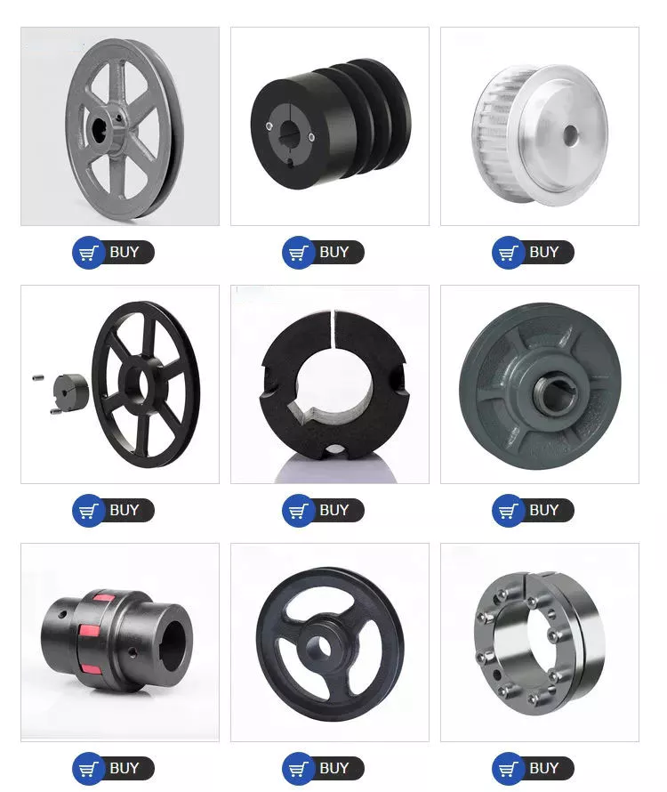
Another use for pulleys is weight lifting. This technique is very effective when using multiple strands of rope. A single rope going from 1 pulley to the other with just 2 hands is not enough to lift heavy objects. Using a pulley system will greatly increase the force you receive. This power is multiplied over a larger area. So your lifting force will be much greater than the force exerted by a single rope.
The pulley is a great invention with many uses. For example, when lifting heavy objects, pulleys are a great way to get the job done, and it’s easier to do than 1 person. The pulley is fixed on a hinge and rotates on a shaft or shaft. Then pull the rope down to lift the object. A pulley assembly will make the task easier. In addition, it will also allow power to be transferred from 1 rotary shaft to another.
pulley

Types of pulleys

If you are an engineer, you must have come across different types of pulleys. Some pulleys come in multiple types, but a typical pulley has only 1 type. These types of pulleys are used in various industrial processes. Here are some common types of pulleys that engineers encounter on the job. In addition to the above, there are many more. If you haven’t seen them in practice, you can check out a list of the different types below.
Fixed pulleys: Fixed pulleys have a roller attached to a fixed point. The force required to pull the load through the fixed pulley is the same as the force required to lift the object. Movable pulleys allow you to change the direction of the force, for example, by moving it laterally. Likewise, movable pulleys can be used to move heavy objects up and down. Commonly used in multi-purpose elevators, cranes and weight lifters.
Composite pulleys combine fixed and movable pulleys. This combination adds to the mechanical advantage of both systems. It can also change the direction of the force, making it easier to handle large loads. This article discusses the different types of pulleys used for lifting and moving. Braided pulleys are an example of these pulleys. They combine the advantages of both types.
A simple pulley consists of 1 or more wheels, which allow it to reverse the direction of the force used to lift the load. On the other hand, dual-wheel pulleys can help lift twice the weight. By combining multiple materials into 1 pulley, a higher ME will be required. Regardless of the type of pulley, understanding the principles behind it is critical.
Pulleys are an important part of construction and mechanical engineering, and their use dates back to Archimedes. They are a common feature of oil derricks and escalators. The main use of pulleys is to move heavy objects such as boats. In addition to this, they are used in other applications such as extending ladders and lifting heavy objects. The pulley also controls the aircraft rudder, which is important in many different applications.

Commonly used

Common uses for pulleys are varied. Pulley systems are found throughout most areas of the house, from adjustable clotheslines to motor pulleys in different machines. Commercially, 1 of the most common uses is for cranes. Cranes are equipped with pulleys to lift heavy objects. It is also common to use pulley systems in tall buildings, which allow tall buildings to move with relative ease.
Pulleys are commonly used in interception and zipline systems, where a continuous rope around the pulley transmits force. Depending on the application, the rope is either light or strong. Pulleys are formed by wrapping a rope around a set of wheels. The rope pulls the object in the direction of the applied force. Some elevators use this system. Pull a cable on 1 end and attach a counterweight on the other end.
Another common use for pulleys is to move heavy objects. Pulleys mounted on walls, ceilings or other objects can lift heavy objects like heavy toolboxes or 2×4 planks. The device can also be used to transfer power from 1 rotating shaft to another. When used to lift heavy objects, pulleys can be used to help you achieve your goals of a good workout.
Pulley systems have a variety of uses, from the most basic to the most advanced. Its popularity is indisputable and it is used in different industries. A good example is timing belts. These pulleys transmit power to other components in the same direction. They can also be static or dynamic depending on the needs of the machine. In most cases, the pulley system is custom made for the job.
Pulley systems can be simple or complex, but all 3 systems transfer energy efficiently. In most cases, the mechanical advantage of a single pulley is 1 and the mechanical advantage of a single active pulley is 2. On the other hand, a single live pulley only doubles the force. This means you can trade effort for distance. Pulleys are the perfect solution for many common applications.
pulley

Safety Notice

If you use pulleys, you need to take some safety precautions. First, make sure you’re wearing the correct protective gear. A hard hat is a must to avoid being hit by falling objects. You may also want to wear gloves for added protection. You should also maintain a good distance from the pulley so that nearby people can walk around it safely.
Another important safety measure to take before using a chain hoist is to barricade the area to be lifted. Use marker lines to prevent the load from sliding when moving horizontally. Finally, use only the sprocket set for vertical lift. Always install shackle pins before lifting. You should also wear personal protective equipment such as earplugs and safety glasses when using the chain hoist.
In addition to these safety measures, you should also use cables made from aerospace-grade nylon. They will last many cycles and are made of high quality materials. Also, make sure the cables are lubricated. These measures reduce friction and corrosion. No matter what industry you are in, be sure to follow these precautions to ensure a long service life for your cables. Consult the cable manufacturer if you are unsure of the appropriate material. A company with 60 years of experience in the cable industry can recommend the right material for your system.

China factory Price of Wheel Loader, Backhoe Loader Spare Parts CZPT     near me supplier China factory Price of Wheel Loader, Backhoe Loader Spare Parts CZPT     near me supplier