Tag Archives: agricultural pump

China OEM Customized CNC Aluminum Turned Forged Stamping Lathe Machined Tractor Guitar ATV Vehicle Valve Pump Boat Trailer Hydraulic Agricultural Industrial Parts agricultural spare parts

Product Description


Product display

Product description:
1-material:
Stainless steel:SS201,SS301,SS303,SS304,SS316,SS416 etc.
Iron:A36,45#,1213,12L14,1215 etc.
Aluminun:AL6061,AL6063,AL6082,AL7075,AL5052 etc.
Copper:C11000,C12000,C36000 etc.
Brass:HPb63,HPb62,HPb61,HPb59,H59,H62,H68,H80 etc.
Steel:mild steel,carbon steel,4140,4340,Q235,Q345B,20#,45# etc.
Plastic:ABS,PP,PEI,Peek,PE,POM,Delrin,Nylon,Teflon etc.

2-Parameter
3/4/5-axis CNCmilling,CNC Turning,dilling etc.
Precision:CNC turning ±0.003mm,CNC Milling ±0.01mm
Test equipment:Project,CMM,Altimeter,Micrometer,Thread Gages,Calipers,Pin Gauge etc.
Drawing Format:IGS,STP,X-T,DXF,Pro/E,PDFA
Workable size: CNC turning :φ0.5-φ300*750mm,CNC milling:510*1571*500mm(max).

3-Finishing:Chrome plating,Nickle plating,Tin plating,Zinc plating,Polishing,Anodizing,Power-coating,Oxide black.electroless nickel etc.

4-OEM&ODM are welcome.welcome to  processing by drawing and sample.we have powerful equipment to support the processing of products.The main equipment:Machining Center,CNC,Lathe,Turning machine,Milling machine,Drilling machine,Internal and external grinding machine,Cylindrical grinding machine,Tapping drilling machine,Wire cutting machine etc.
 
5-Delivery time:5-25days after the confirmation of sample(according to order quatity.)
   The mode of transportation:Express,by sea or by air(according to customer needs)
   Parking:carton/wooden box/other

12 years more experienced  engineers team and well trained sales team to support every project.We need long-term customers,excellent products quality and competitive price are our basic to achieve it.
why choose us?because we are professional.Place your order and we’ll take care of the rest.
Thank you.

US $1-65
/ Piece
|
5 Pieces

(Min. Order)

###

After-sales Service: Ensure That The Design Meets The Requirements
Warranty: Ensure That The Design Meets The Requirements
Application: Metal/Stainless Steel/Aluminum Alloy/Plastic/Other
Process Usage: Metal-Cutting CNC Machine Tools, CNC Non-Conventional Machine Tools, Metal-Forming CNC Machine Tools
Movement Method: Linear Control
Control Method: Closed-Loop Control

###

Samples:
US$ 50/Piece
1 Piece(Min.Order)

|
Request Sample

###

Customization:

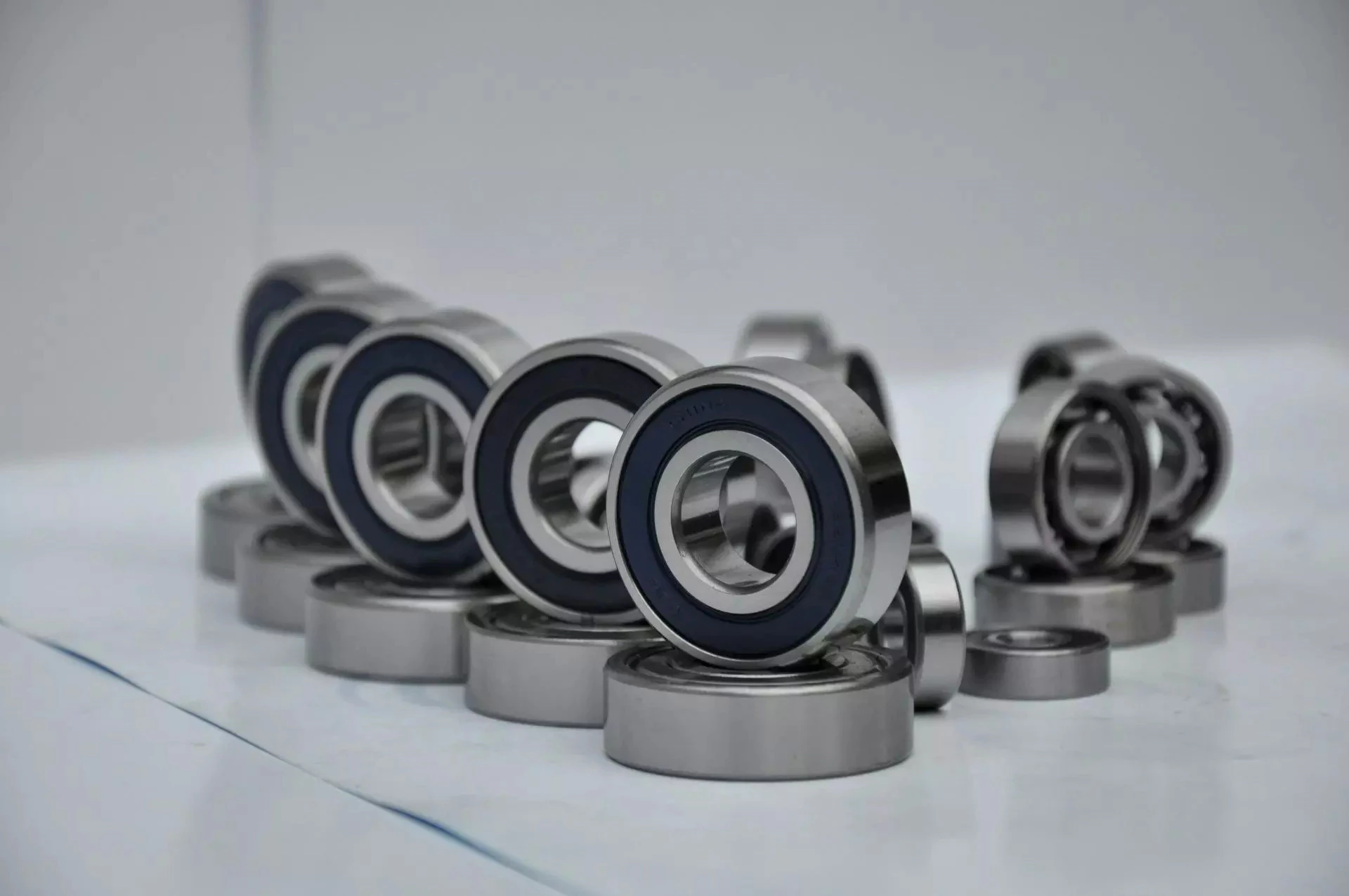
Types of Ball Bearings

In their most basic form, Ball Bearings have one common feature – they are made of steel. The majority of these bearings are made of 52100 steel, which has one percent chromium and one percent carbon. The steel can be hardened by heat trea
tment. 440C stainless steel is used for rusting problems. A cage around the ball balls is traditionally made from thin steel. However, some bearings use molded plastic cages to save money and friction.
bearing

Single-row designs

Steel linear translation stages often use single-row designs for ball bearings. These types of bearings provide smooth linear travel and can withstand high loads. The material steel has a high modulus of elasticity and a high stiffness, as well as a lower thermal expansion than aluminum. For these reasons, steel is the material of choice for a ball bearing in a typical user environment. Single-row designs for ball bearings are also suitable for applications in humid or corrosive environments.
Single-row designs for ball bearings are available in a variety of sizes and are axially adjustable. They have a high radial capacity, but require relatively little space. Single-row deep groove ball bearings with snap rings are STN 02 4605 or R47, respectively. Bearings with snap rings are identified by a suffix such as NR. They may not have seals or shields installed.
These single-row angular contact ball bearings are capable of supporting axial and radial loads. In a two-raceway arrangement, the radial load on bearing A causes a radial load to act on bearing B. Both axial and radial forces are transmitted between single-row angular contact ball bearings, and the resulting internal force must be taken into account to calculate equivalent dynamic bearing loads P.
Single-row deep groove ball bearings are the most common type of ball bearings. These bearings are designed with only one row of rolling elements. The single-row design is simple and durable, which makes it ideal for high-speed applications. Single-row designs for ball bearings are also available in various bore sizes. They can also come in a variety of shapes and are non-separable. If you need a high-speed bearing, you may want to opt for a double-row design.
In addition to single-row designs for ball bearings, you can choose ceramic or steel ball bearings. Ceramic balls are considerably harder than steel balls, but they are not as hard as steel. Hence, ceramic bearings are stiffer than steel ball bearings, resulting in increased stress on the outer race groove and lower load capacity. This is a great benefit for those who need the bearings to be lightweight and strong.
The difference between single-row and double-row designs is in the way that the inner and outer ring are installed. A single-row design places the inner ring in an eccentric position relative to the outer ring. The two rings are in contact at one point, which causes a large gap in the bearing. The balls are then inserted through the gap. As a result, the balls are evenly distributed throughout the bearing, which forces the inner and outer rings to become concentric.
Deep-groove ball bearings are one of the most popular types of ball bearings. They are available in different designs, including snap-ring, seal and shield arrangements. The race diameter of a deep-groove ball bearing is close to the ball’s diameter. These types of bearings are suited for heavy loads, and their axial and radial support are excellent. Their main drawback is that the contact angle cannot be adjusted to accommodate a wide range of relative loads.
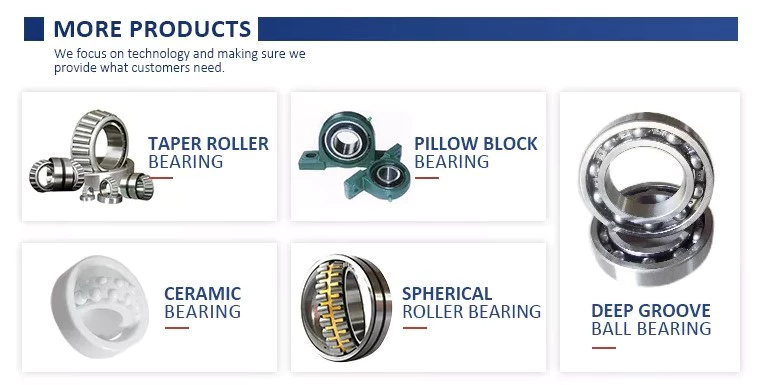
bearing

Ceramic hybrid ball bearings

Hybrid ball bearings with ceramic balls have numerous advantages. They feature improved kinematic behavior and require less lubrication. Consequently, they can reduce operating costs. Additionally, their low thermal expansion coefficient allows for smaller changes in contact angle and preload variations, and they can retain tolerances. Furthermore, ceramic hybrid ball bearings have significantly increased life spans compared to conventional steel-steel ball bearings, with up to 10 times the lifespan.
Although ceramic bearings can be used in automotive applications, many people believe that they’re a poor choice for bicycle hubs. They don’t reduce weight and only work well in high-rpm environments. As a result, many cyclists don’t even bother with ceramic-based bearings. However, both Paul Lew and Alan are of the opinion that ceramic bearings are best suited for industrial or medical equipment applications. Furthermore, Paul and Alan believe that they are ideal for high-altitude drone motors.
Another advantage of ceramic hybrid ball bearings is that they use less friction than conventional steel-based balls. They are also more durable, requiring less lubrication than steel-based bearings. Furthermore, the lower friction and rolling resistance associated with ceramic-based ball bearings means that they can last ten times longer than steel-based bearings. A ceramic-based hybrid ball bearing can be used for applications where speed and lubrication are critical.
Ceramic hybrid ball bearings feature both steel and silicon nitride balls. Silicon nitride balls have 50% more modulus of elasticity than steel balls and can improve accuracy and precision. Ceramic balls also have a smoother surface finish than steel balls, which reduces vibration and spindle deflection. These benefits result in increased speed and improved production quality. In addition to this, ceramic balls can also reduce the operating temperature, enhancing the work environment.
Hybrid bearings are a popular alternative to steel bearings. They have some benefits over traditional steel bearings, and are becoming a popular choice for engineered applications. Hybrid bearings are ideal for high speed machines. The material used to manufacture ceramic balls is a high-quality alloy, and is comparatively inexpensive. But you must understand that lubrication is still necessary for hybrid bearings. If you are not careful, you may end up wasting money.
These ball bearings can be used in many industries and applications, and they are widely compatible with most metals. The main advantage of hybrid ball bearings is that they are very durable. While steel balls tend to corrode and wear out, ceramic ball bearings can withstand these conditions while minimizing maintenance and replacement costs. The benefits of hybrid ball bearings are clear. So, consider switching to these newer types of ball bearings.
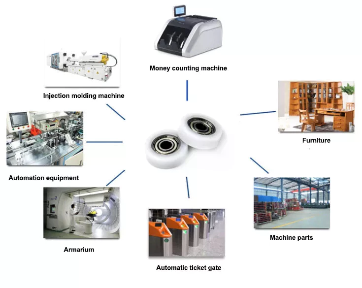
bearing

Self-aligning ball bearings

Self-aligning ball bearings are a good choice for many applications. They are a great alternative to traditional ball bearings, and they are ideal for rotating applications in which the shaft must move in several directions. They are also ideal for use in rotating parts where a tight tolerance is necessary. You can choose between two types: plain and flex shaft. Read on to find out which one will suit your needs.
Self-aligning ball bearings are designed with a higher axial load carrying capacity than single-row radial deep groove ball bearings. The amount of axial load carrying capacity is dependent upon the pressure angle. These bearings have a hollow raceway in the outer ring that allows the inner ring to pivot without friction. They are often used for high-speed applications. Because of their design, they are highly accurate.
Self-aligning ball bearings are radial bearings that feature two rows of balls in a spherical outer ring. They also feature two deep uninterrupted raceway grooves in the inner ring. Their unique features make them an excellent choice for applications where shaft deflection is a significant factor. Despite their small size, they have a high level of precision and can withstand heavy loads.
Self-aligning ball bearings can compensate for misalignment in shaft applications. The inner ring and ball assembly are positioned inside an outer ring containing a curved raceway. This spherical design allows the balls and cage to deflect and re-align around the bearing center. These bearings are also ideal for applications where shaft deflection is significant, such as in simple woodworking machinery.
Another type of self-aligning ball bearing uses a common concave outer race. Both balls and outer races automatically compensate for angular misalignment caused by machining, assembly, and deflections. Compared to spherical rollers, they have lower frictional losses than their spherical counterparts. Self-alignment ball bearings also have lower vibration levels compared to other types of bearings.
Self-aligning ball bearings operate in misaligned applications because their spherical outer raceway can accommodate misalignment. This design allows them to work in applications where shaft deflection or housing deformation is common. They are therefore more suitable for low to medium-sized loads. The only real drawback to self-aligning ball bearings is their price. If you need to purchase a self-aligning ball bearing for your next project, you can expect to pay around $1500.

China OEM Customized CNC Aluminum Turned Forged Stamping Lathe Machined Tractor Guitar ATV Vehicle Valve Pump Boat Trailer Hydraulic Agricultural Industrial Parts     agricultural spare partsChina OEM Customized CNC Aluminum Turned Forged Stamping Lathe Machined Tractor Guitar ATV Vehicle Valve Pump Boat Trailer Hydraulic Agricultural Industrial Parts     agricultural spare parts
editor by czh 2022-11-28

China Standard Shenzhen OEM Customized CNC Aluminum Turned Forged Stamping Lathe Machined Tractor ATV/UTV Vehicle Valve Pump Trailer Hydraulic Agricultural Industrial Parts with Best Sales

Product Description

                                                                 A Letter to Our Future Partners
Dear,

Plz wait don’t scroll. No doubt, that partner is you! Thank you for visiting our Xielifeng CNC machining service at MIC now.

Xielifeng Tech is located in HangZhou, China, which focuses on CNC machining, including milling, turning, auto-lathe, die casting. Both metal and plastic material are within our capability. We provide one-stop service, from professional design analysis, to free quote, fast prototype, ISO standard manufacturing, to safe shipping and great after-sales services.

 During these years, we have win lots of trust in the global market, most of them come from North America and Europe. Now you may have steady suppliers, but still hope you can keep us in the archives to get more market news.

More interests, feel free to send us an inquiry via Contact now, or directly to our email, and then our professional sales manager will get back to you ASAP!

Warmly regards.
Peter Tu (Sales Manager)


Service Custom CNC Machining Parts of Most Materials
Quotation According to your drawing(size, material, thickness, processing content, and required technology, etc)
Tolerance & Surface Roughness +/-0.005 – 0.1mm & Ra0.2 – Ra3.2 (Customize available)
Materials Available Aluminum, Copper, Stainless steel, Iron, PE, PVC, ABS, etc.
Surface Treatment Polishing, general/hard/color oxidation, surface chamfering, tempering, etc.
Processing CNC Turning, Milling, Drilling, Auto Lathe, Tapping, Bushing, Surface Treatment, etc.
Payment method Our business face global. and support credit cards, T/T, L/C, Paypal, etc.
Drawing Formats PRO/E, Auto CAD, Solid Works , UG, CAD / CAM / CAE, PDF

FAQ: 

Q1: Where can I get product&price information?
A1: Send us an inquiry in this page or e-mail, we will contact you after upon receipt of your mail.

Q2: How soon can I get samples and how much the fee?
A2: Depending on your specific project, it usually takes 10 to 20 days. the fee depends on the product drawing, and the fee will be returned to your bulk order.

Q3: How to enjoy the OEM services?
A3: Usually, base on your design drawings or original samples, we give some technical proposals and a quotation to you, after your agreement, we produce for you.

Q4: Can you make machining parts based on our samples?
A4: Yes, we can make measurements based on your samples to make drawings for machining parts making.

Q5: Is it possible to know how are my products going on without visiting your company?
A5: We will offer a detailed production schedule and send weekly reports with digital pictures and videos which show the machining progress.

Q6: Will my drawing safe after you get it?
A6: Yes, we can sign the NDA before got your drawing.

Synthesis of Epicyclic Gear Trains for Automotive Automatic Transmissions

In this article, we will discuss the synthesis of epicyclic gear trains for automotive automatic transmissions, their applications, and cost. After you have finished reading, you may want to do some research on the technology yourself. Here are some links to further reading on this topic. They also include an application in hybrid vehicle transmissions. Let’s look at the basic concepts of epicyclic gear trains. They are highly efficient and are a promising alternative to conventional gearing systems.
Gear

Synthesis of epicyclic gear trains for automotive automatic transmissions

The main purpose of automotive automatic transmissions is to maintain engine-drive wheel balance. The kinematic structure of epicyclic gear trains (EGTs) is derived from graph representations of these gear trains. The synthesis process is based on an algorithm that generates admissible epicyclic gear trains with up to 10 links. This algorithm enables designers to design auto gear trains that have higher performance and better engine-drive wheel balance.
In this paper, we present a MATLAB optimization technique for determining the gear ratios of epicyclic transmission mechanisms. We also enumerate the number of teeth for all gears. Then, we estimate the overall velocity ratios of the obtained EGTs. Then, we analyze the feasibility of the proposed epicyclic gear trains for automotive automatic transmissions by comparing their structural characteristics.
A six-link epicyclic gear train is depicted in the following functional diagram. Each link is represented by a double-bicolor graph. The numbers on the graph represent the corresponding links. Each link has multiple joints. This makes it possible for a user to generate different configurations for each EGT. The numbers on the different graphs have different meanings, and the same applies to the double-bicolor figure.
In the next chapter of this article, we discuss the synthesis of epicyclic gear trains for automotive automatic transaxles. SAE International is an international organization of engineers and technical experts with core competencies in aerospace and automotive. Its charitable arm, the SAE Foundation, supports many programs and initiatives. These include the Collegiate Design Series and A World In Motion(r) and the SAE Foundation’s A World in Motion(r) award.
Gear

Applications

The epicyclic gear system is a type of planetary gear train. It can achieve a great speed reduction in a small space. In cars, epicyclic gear trains are often used for the automatic transmission. These gear trains are also useful in hoists and pulley blocks. They have many applications in both mechanical and electrical engineering. They can be used for high-speed transmission and require less space than other types of gear trains.
The advantages of an epicyclic gear train include its compact structure, low weight, and high power density. However, they are not without disadvantages. Gear losses in epicyclic gear trains are a result of friction between gear tooth surfaces, churning of lubricating oil, and the friction between shaft support bearings and sprockets. This loss of power is called latent power, and previous research has demonstrated that this loss is tremendous.
The epicyclic gear train is commonly used for high-speed transmissions, but it also has a small footprint and is suitable for a variety of applications. It is used as differential gears in speed frames, to drive bobbins, and for the Roper positive let-off in looms. In addition, it is easy to fabricate, making it an excellent choice for a variety of industrial settings.
Another example of an epicyclic gear train is the planetary gear train. It consists of 2 gears with a ring in the middle and the sun gear in the outer ring. Each gear is mounted so that its center rotates around the ring of the other gear. The planet gear and sun gear are designed so that their pitch circles do not slip and are in sync. The planet gear has a point on the pitch circle that traces the epicycloid curve.
This gear system also offers a lower MTTR than other types of planetary gears. The main disadvantage of these gear sets is the large number of bearings they need to run. Moreover, planetary gears are more maintenance-intensive than parallel shaft gears. This makes them more difficult to monitor and repair. The MTTR is also lower compared to parallel shaft gears. They can also be a little off on their axis, causing them to misalign or lose their efficiency.
Another example of an epicyclic gear train is the differential gear box of an automobile. These gears are used in wrist watches, lathe machines, and automotives to transmit power. In addition, they are used in many other applications, including in aircrafts. They are quiet and durable, making them an excellent choice for many applications. They are used in transmission, textile machines, and even aerospace. A pitch point is the path between 2 teeth in a gear set. The axial pitch of 1 gear can be increased by increasing its base circle.
An epicyclic gear is also known as an involute gear. The number of teeth in each gear determines its rate of rotation. A 24-tooth sun gear produces an N-tooth planet gear with a ratio of 3/2. A 24-tooth sun gear equals a -3/2 planet gear ratio. Consequently, the epicyclic gear system provides high torque for driving wheels. However, this gear train is not widely used in vehicles.
Gear

Cost

The cost of epicyclic gearing is lower when they are tooled rather than manufactured on a normal N/C milling machine. The epicyclic carriers should be manufactured in a casting and tooled using a single-purpose machine that has multiple cutters to cut the material simultaneously. This approach is widely used for industrial applications and is particularly useful in the automotive sector. The benefits of a well-made epicyclic gear transmission are numerous.
An example of this is the planetary arrangement where the planets orbit the sun while rotating on its shaft. The resulting speed of each gear depends on the number of teeth and the speed of the carrier. Epicyclic gears can be tricky to calculate relative speeds, as they must figure out the relative speed of the sun and the planet. The fixed sun is not at zero RPM at mesh, so the relative speed must be calculated.
In order to determine the mesh power transmission, epicyclic gears must be designed to be able to “float.” If the tangential load is too low, there will be less load sharing. An epicyclic gear must be able to allow “float.” It should also allow for some tangential load and pitch-line velocities. The higher these factors, the more efficient the gear set will be.
An epicyclic gear train consists of 2 or more spur gears placed circumferentially. These gears are arranged so that the planet gear rolls inside the pitch circle of the fixed outer gear ring. This curve is called a hypocycloid. An epicyclic gear train with a planet engaging a sun gear is called a planetary gear train. The sun gear is fixed, while the planet gear is driven.
An epicyclic gear train contains several meshes. Each gear has a different number of meshes, which translates into RPM. The epicyclic gear can increase the load application frequency by translating input torque into the meshes. The epicyclic gear train consists of 3 gears, the sun, planet, and ring. The sun gear is the center gear, while the planets orbit the sun. The ring gear has several teeth, which increases the gear speed.
Another type of epicyclic gear is the planetary gearbox. This gear box has multiple toothed wheels rotating around a central shaft. Its low-profile design makes it a popular choice for space-constrained applications. This gearbox type is used in automatic transmissions. In addition, it is used for many industrial uses involving electric gear motors. The type of gearbox you use will depend on the speed and torque of the input and output shafts.

China Standard Shenzhen OEM Customized CNC Aluminum Turned Forged Stamping Lathe Machined Tractor ATV/UTV Vehicle Valve Pump Trailer Hydraulic Agricultural Industrial Parts     with Best SalesChina Standard Shenzhen OEM Customized CNC Aluminum Turned Forged Stamping Lathe Machined Tractor ATV/UTV Vehicle Valve Pump Trailer Hydraulic Agricultural Industrial Parts     with Best Sales

China best Stainless Steel Pesticide High Pressure Sprayer Farm Battery Agricultural Pump Drones Spare Part wholesaler

Product Description

FAQ:

1)MOQ

Answer:Different from every item.Could you please confirm with our staff?

 
2)Sample

Answer:We can provide sample before formal order.But I am afraid it is not free.

Leave message about sample quantity our staff will reply you on time.

 
3)After-sales Service Provided

Answer:We will provide free replacement accessories if it broken within a year.

 
4)Delivery time

Answer:Different from quantity.Leave message about quantity our staff will reply you on time.

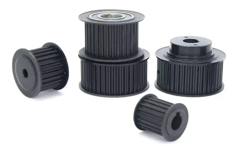
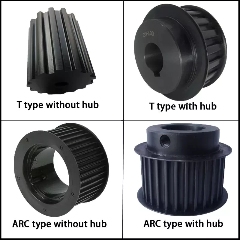
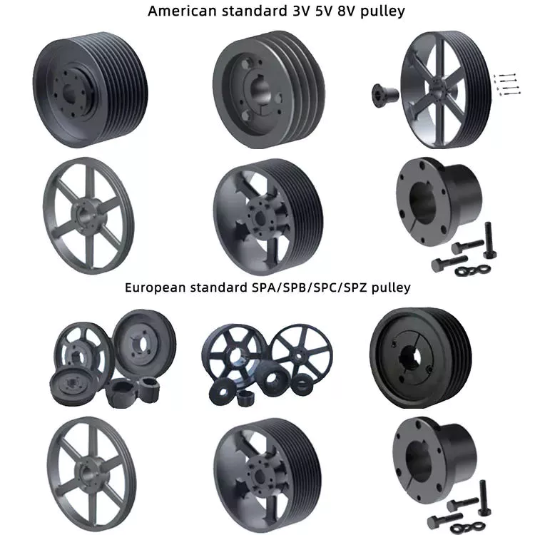
The importance of pulleys

A pulley is a wheel that rides on an axle or axle. The purpose of the pulley is to change the direction of the tensioning cable. The cable then transfers the power from the shaft to the pulley. This article explains the importance of pulleys and demonstrates several different uses for this machine. Also, see the Mechanical Advantages section below for the different types. let’s start.
pulley

simple machine

A simple pulley machine is a device used to transfer energy. It consists of a wheel with flexible material on the rim and a rope or chain tied to the other end. Then lift the load using the force applied to the other end. The mechanical advantage of this system is one, as the force applied to the load is the same as the force on the pulley shaft.
A simple pulley machine has many benefits, from the ability to build pyramids to building modern buildings with it. Pulleys are also popular with children because they can perform simple tasks such as lifting toys onto a slide, sliding them off the slide, and lifting them up again. These activities, called “transportation” by child development theorists, allow them to learn about the physics of simple machines in the process.
The mechanism works by using cables to transmit force. The cable is attached to 1 side of the pulley and the other side is pulled by the user. Lift the load by pulling on 1 end and the other end of the rope. Simple pulley machines have many commercial and everyday applications, including helping move large objects. They can be fixed or movable, and can be a combination of both. The present invention is a great tool for any beginner or engineer.

axis

The axle wheel is the basic mechanical part that amplifies the force. It may have originally appeared as a tool to lift buckets or heavy objects from a well. Its operation is demonstrated by large and small gears attached to the same shaft. When applied to an object, the force on the large gear F overcomes the force W on the pinion R. The ratio of these 2 forces is called the mechanical advantage.
The ideal mechanical advantage of shaft pulleys is their radius ratio. A large radius will result in a higher mechanical advantage than a small radius. A pulley is a wheel through which a rope or belt runs. Often the wheels are interconnected with cables or belts for added mechanical advantage. The number of support ropes depends on the desired mechanical advantage of the pulley.
In the design of the axle wheel, the axle is the fulcrum and the outer edge is the handle. In simple terms, wheels and axle pulleys are improved versions of levers. The axle pulley moves the load farther than the lever and connects to the load at the center of the axle. Shaft pulleys are versatile and widely used in construction.

rope or belt

Ropes or pulleys are mechanical devices used to move large masses. The rope supports a large mass and can be moved easily by applying a force equal to 1 quarter of the mass to the loose end. Quad pulleys have 4 wheels and provide the mechanical advantage of 4 wheels. It is often used in factories and workshops. It is also a popular choice in the construction industry. If you are installing a pulley in your vehicle, be sure to follow these simple installation instructions.
First, you need to understand the basics of how a rope or pulley works. The machine consists of 1 or more wheels that rotate on an axle. The rope or belt is wrapped around the pulley and the force exerted on the rope is spread around the pulley. It then transfers the force from 1 end of the rope to the other. The pulley system also helps reduce the force required to lift objects.
Another common rope or pulley is the differential pulley. This is similar to a rope pulley, but consists of 2 pulleys of different radii. The tension in the 2 halves of the rope supports half the load that the live pulley should carry. These 2 different types of pulleys are often used together in composite pulley systems.
pulley

Mechanical advantage

The mechanical advantage is the ratio of the force used to move the load through the pulley system to the force applied. It has been used to measure the effectiveness of pulley systems, but it also requires assumptions about applied forces and weights. In a simple 1:1 pulley system, the weight lifting the weight is the same as the weight of the person pulling the weight. Adding mechanical advantage can help make up for the lack of manpower.
This advantage stems from the mechanical properties of simple machines. It requires less force and takes up less space and time to accomplish the same task. The same effect can also be achieved by applying less force at a distance. Furthermore, this effect is called the output force ratio. The basic working principle of a pulley system is a rope with a fixed point at 1 end. The movable pulley can be moved with very little force to achieve the desired effect.
The load can be moved through the vertical entry using a simple pulley system. It can use a simple “pulley block” system with a 2:1 “ladder frame” or a 4:1 with dual pulleys. This can be combined with another simple pulley system to create a compound pulley system. In this case, a simple pulley system is pulling another pulley, giving it a 9:1 mechanical advantage.

Commonly used

You’ve probably seen pulley systems in your kitchen or laundry room. You probably already use it to hang clothes on an adjustable clothesline. You may have seen motor pulleys in the kitchens of commercial buildings. You might even have seen 1 on a crane. These machines use a pulley system to help them lift heavy loads. The same goes for theaters. Some pulleys are attached to the sides of the stage, enabling the operator to move up and down the stage.
Pulley systems have many uses in the oil and petroleum industry. For example, in the oil and gas industry, pulley systems are used to lay cables. They are arranged in a pulley structure to provide mechanical energy. When the rope is running, 2 pulleys are hung on the derrick to facilitate smooth running. In these applications, pulleys are very effective in lifting heavy objects.
A pulley is a simple mechanical device that converts mechanical energy into motion. Unlike chains, pulleys are designed to transfer power from 1 location to another. The force required to lift an object with a pulley is the same as that required by hand. It takes the same amount of force to lift a bucket of water, but it’s more comfortable to pull sideways. A bucket of water weighs the same as when lifted vertically, so it’s easy to see how this mechanism can be useful.
pulley

Safety Notice

When using pulleys, you should take several safety precautions to keep your employees and other workers on the job site safe. In addition to wearing a hard hat, you should also wear gloves to protect your hands. Using pulleys can lead to a variety of injuries, so it’s important to keep these precautions in mind before using pulleys. Here are some of the most common:
Pulleys are an important piece of equipment to have on hand when lifting heavy objects. Pulleys not only reduce the force required to lift an object, but also the direction of the force. This is especially important if you are lifting heavy objects, such as a lawn mower or motorcycle. Before starting, it is important to make sure that the anchoring system can support the full weight of the object you are lifting.
When using a pulley system, make sure the anchor points are adequate to support the load. Check with the pulley manufacturer to determine the weight it can safely lift. If the load is too large, composite pulleys can be used instead. For vertical lifts, you should use a sprocket set and wear personal protective equipment. Safety precautions when using pulleys are critical to worker health and safety.

China best Stainless Steel Pesticide High Pressure Sprayer Farm Battery Agricultural Pump Drones Spare Part     wholesaler China best Stainless Steel Pesticide High Pressure Sprayer Farm Battery Agricultural Pump Drones Spare Part     wholesaler