Tag Archives: china machine

China wholesaler Ruijp Different Thickness Good Quality Full Automatic Tractor Washing Machine Parts with Best Sales

Product Description

Ruijp Different Thickness Good Quality Full Automatic Tractor Washing Machine Parts


Product Description

1. Drain control commonly used in washing machine/air conditioner/  dishwasher and so on.

2. The Drain control enjoy their high efficiency, low energy consumption,long life and low noise.

3.A variety of Drain control design for customer choice, can also be designed according to customer requirements.

4.Different thickness of the iron core is suitable for all kinds of customers’ requirements.

5.The certification of TUV, UL, CCC

6.Good quality drain pump with low price. If you want drain pump more details , pls don’t hesitate to contact us.

7.The technical parameters depending on the customer’s requirements.

Name Drain control
Type Washing machine parts
Voltage 110-127V/220-240V
Frequency 50/60Hz


Technical parameters

Main products


Company Profile

Workshop

Exhibition

Certifications

FAQ


1 Q: Are you a manufacturer or trading company?

A:We are professional drain pump and motor manufacturer for almost 10 years.

2. Q: What’s your delivery time?

A: 1. The stock samples can be sent to you within 3-5 days by international express.

2. The batch order can be shipped to you in about 25-30 days after order confirmation( by air or by sea).

3 Q: Is it all right to make customer’s own brand name?

A:Yes, we accept OEM.

4 Q: What is your loading port?

A:Xihu (West Lake) Dis. port.

5 Q: What are your payment terms?

A:We can acceptT/T,L/C,DP,.


Any more question.Please contact us without any hesitation.

Types of Splines

There are 4 types of splines: Involute, Parallel key, helical, and ball. Learn about their characteristics. And, if you’re not sure what they are, you can always request a quotation. These splines are commonly used for building special machinery, repair jobs, and other applications. The CZPT Manufacturing Company manufactures these shafts. It is a specialty manufacturer and we welcome your business.
splineshaft

Involute splines

The involute spline provides a more rigid and durable structure, and is available in a variety of diameters and spline counts. Generally, steel, carbon steel, or titanium are used as raw materials. Other materials, such as carbon fiber, may be suitable. However, titanium can be difficult to produce, so some manufacturers make splines using other constituents.
When splines are used in shafts, they prevent parts from separating during operation. These features make them an ideal choice for securing mechanical assemblies. Splines with inward-curving grooves do not have sharp corners and are therefore less likely to break or separate while they are in operation. These properties help them to withstand high-speed operations, such as braking, accelerating, and reversing.
A male spline is fitted with an externally-oriented face, and a female spline is inserted through the center. The teeth of the male spline typically have chamfered tips to provide clearance with the transition area. The radii and width of the teeth of a male spline are typically larger than those of a female spline. These specifications are specified in ANSI or DIN design manuals.
The effective tooth thickness of a spline depends on the involute profile error and the lead error. Also, the spacing of the spline teeth and keyways can affect the effective tooth thickness. Involute splines in a splined shaft are designed so that at least 25 percent of the spline teeth engage during coupling, which results in a uniform distribution of load and wear on the spline.

Parallel key splines

A parallel splined shaft has a helix of equal-sized grooves around its circumference. These grooves are generally parallel or involute. Splines minimize stress concentrations in stationary joints and allow linear and rotary motion. Splines may be cut or cold-rolled. Cold-rolled splines have more strength than cut spines and are often used in applications that require high strength, accuracy, and a smooth surface.
A parallel key splined shaft features grooves and keys that are parallel to the axis of the shaft. This design is best suited for applications where load bearing is a primary concern and a smooth motion is needed. A parallel key splined shaft can be made from alloy steels, which are iron-based alloys that may also contain chromium, nickel, molybdenum, copper, or other alloying materials.
A splined shaft can be used to transmit torque and provide anti-rotation when operating as a linear guide. These shafts have square profiles that match up with grooves in a mating piece and transmit torque and rotation. They can also be easily changed in length, and are commonly used in aerospace. Its reliability and fatigue life make it an excellent choice for many applications.
The main difference between a parallel key splined shaft and a keyed shaft is that the former offers more flexibility. They lack slots, which reduce torque-transmitting capacity. Splines offer equal load distribution along the gear teeth, which translates into a longer fatigue life for the shaft. In agricultural applications, shaft life is essential. Agricultural equipment, for example, requires the ability to function at high speeds for extended periods of time.
splineshaft

Involute helical splines

Involute splines are a common design for splined shafts. They are the most commonly used type of splined shaft and feature equal spacing among their teeth. The teeth of this design are also shorter than those of the parallel spline shaft, reducing stress concentration. These splines can be used to transmit power to floating or permanently fixed gears, and reduce stress concentrations in the stationary joint. Involute splines are the most common type of splined shaft, and are widely used for a variety of applications in automotive, machine tools, and more.
Involute helical spline shafts are ideal for applications involving axial motion and rotation. They allow for face coupling engagement and disengagement. This design also allows for a larger diameter than a parallel spline shaft. The result is a highly efficient gearbox. Besides being durable, splines can also be used for other applications involving torque and energy transfer.
A new statistical model can be used to determine the number of teeth that engage for a given load. These splines are characterized by a tight fit at the major diameters, thereby transferring concentricity from the shaft to the female spline. A male spline has chamfered tips for clearance with the transition area. ANSI and DIN design manuals specify the different classes of fit.
The design of involute helical splines is similar to that of gears, and their ridges or teeth are matched with the corresponding grooves in a mating piece. It enables torque and rotation to be transferred to a mate piece while maintaining alignment of the 2 components. Different types of splines are used in different applications. Different splines can have different levels of tooth height.

Involute ball splines

When splines are used, they allow the shaft and hub to engage evenly over the shaft’s entire circumference. Because the teeth are evenly spaced, the load that they can transfer is uniform and their position is always the same regardless of shaft length. Whether the shaft is used to transmit torque or to transmit power, splines are a great choice. They provide maximum strength and allow for linear or rotary motion.
There are 3 basic types of splines: helical, crown, and ball. Crown splines feature equally spaced grooves. Crown splines feature involute sides and parallel sides. Helical splines use involute teeth and are often used in small diameter shafts. Ball splines contain a ball bearing inside the splined shaft to facilitate rotary motion and minimize stress concentration in stationary joints.
The 2 types of splines are classified under the ANSI classes of fit. Fillet root splines have teeth that mesh along the longitudinal axis of rotation. Flat root splines have similar teeth, but are intended to optimize strength for short-term use. Both types of splines are important for ensuring the shaft aligns properly and is not misaligned.
The friction coefficient of the hub is a complex process. When the hub is off-center, the center moves in predictable but irregular motion. Moreover, when the shaft is centered, the center may oscillate between being centered and being off-center. To compensate for this, the torque must be adequate to keep the shaft in its axis during all rotation angles. While straight-sided splines provide similar centering, they have lower misalignment load factors.
splineshaft

Keyed shafts

Essentially, splined shafts have teeth or ridges that fit together to transfer torque. Because splines are not as tall as involute gears, they offer uniform torque transfer. Additionally, they provide the opportunity for torque and rotational changes and improve wear resistance. In addition to their durability, splined shafts are popular in the aerospace industry and provide increased reliability and fatigue life.
Keyed shafts are available in different materials, lengths, and diameters. When used in high-power drive applications, they offer higher torque and rotational speeds. The higher torque they produce helps them deliver power to the gearbox. However, they are not as durable as splined shafts, which is why the latter is usually preferred in these applications. And while they’re more expensive, they’re equally effective when it comes to torque delivery.
Parallel keyed shafts have separate profiles and ridges and are used in applications requiring accuracy and precision. Keyed shafts with rolled splines are 35% stronger than cut splines and are used where precision is essential. These splines also have a smooth finish, which can make them a good choice for precision applications. They also work well with gears and other mechanical systems that require accurate torque transfer.
Carbon steel is another material used for splined shafts. Carbon steel is known for its malleability, and its shallow carbon content helps create reliable motion. However, if you’re looking for something more durable, consider ferrous steel. This type contains metals such as nickel, chromium, and molybdenum. And it’s important to remember that carbon steel is not the only material to consider.

China wholesaler Ruijp Different Thickness Good Quality Full Automatic Tractor Washing Machine Parts     with Best SalesChina wholesaler Ruijp Different Thickness Good Quality Full Automatic Tractor Washing Machine Parts     with Best Sales

China Best Sales Small 10tpd Combined Rice Mill Rice Milling Machine Parts near me manufacturer

Product Description

Small10tpd Combined Rice Mill Rice Machine Parts 

1. Introduction of our modern small rice machine:
SD-SRM01 Complete Set Combined Rice Mill combined with Rice Cleaner, TQLQ45 De-stoner, Husker, Separator, Rice Whitener, Rice Grader, Elevators, Motors & Spare Parts. It features great paddy and husked rice separating performance, easy operation, convenient maintenance and high working efficiency. It is the most advanced combined rice mill in the present market.

2.  Product Features of rice mill machine

  • Automatic operation from the paddy loading to milled white rice.
  • Integrated outfit design, more convenient installation & minimized space occupation. UNIQUE “Rehusking” design, improves milling yield.
  • Build-in Paddy Separator, high separating rate.
  • Creative “Emery Roll Whitening” Design, improved rice whitening accuracy.
  • High quality milled white rice & low broken rate.
  • Whitening/Polishing mechanism, Low rice temperature, less bran remains.
  • Equipped with Rice Grader System to improve the polished rice level
  • Build-in Control Panel, more convenient operation.
  • Improved transmission system, extend the lifespan of wearing parts.
  • Low investment & high profits.
  • Diesel engine driving mechanism optional

3. Specification of combined rice machine:  

1. Model SD-SRM01
2. Capacity 1000-1200kg/h
3. Power  24kw, 380v, 50hz
4. Broken rice rate  2-3%
5. Operation  Automatic
6. Functions  Cleaner–destoner–rice husk–rice separator–rice whitener–rice grader

4.Main pictures of small rice mill machine

5. More choice for complete rice line:
We can also supply 20-300ton/day complete rice mill machinery and different kinds of machines like husker, destoner, rice grader, color sorter, paddy dryer, etc.We can also supply the parboiled rice line,our rice plants have installed successfully in Nigeria, Thailand, India,  Sri Lanka,  Indonesia and so on.

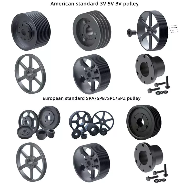
Types of pulleys and their advantages and disadvantages

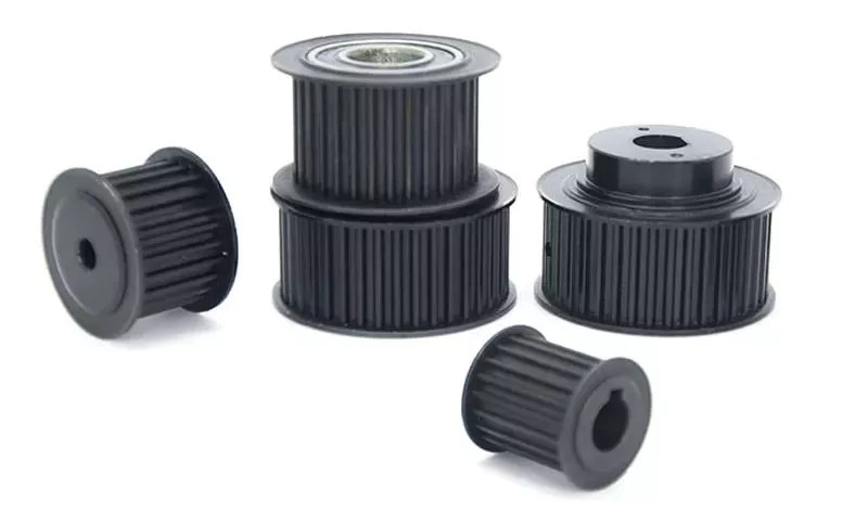
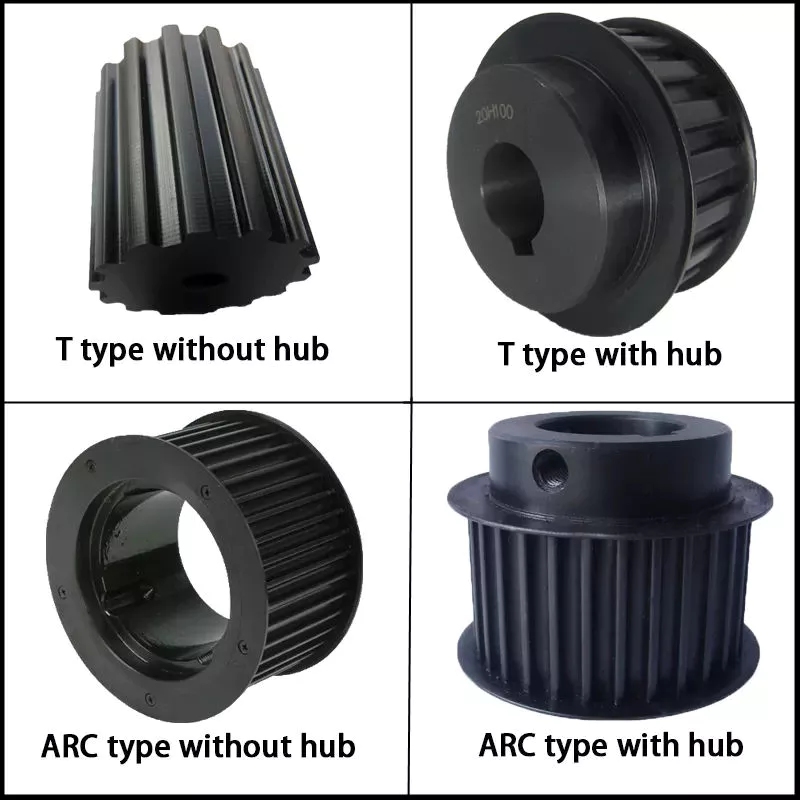
There are several types of pulleys. Learn the basic equations of the pulley system. Then learn about the different uses for pulleys. The disadvantages of using pulleys will be covered. Knowing these, you can buy the pulley that suits your needs. Here are some of the best pulley types and their pros and cons.
pulley

Basic equations of pulley systems

A pulley system is a mechanism that allows 2 blocks of a certain mass to be connected by a taut rope. The acceleration of each block is the same in magnitude and direction. The external force acting on each block is the weight of the block (10g) and the tension in the string. The tension between the 2 blocks is the total tension and the force acting on the pulley is the weight of the 2 blocks.
This simple mechanism uses 2 simple equations to explain how the system works. First, the mass of the weight on both sides of the pulley must be the same. When the weight is forced to move, the rope tightens and the second pulley descends. The weight is also attached to the second pulley and must be the same distance as the first pulley. This will result in a speed ratio of 2 times the distance covered by the first pulley.
Second, we have to calculate the force required to lift the object. The lower mass is supported by a wire configuration passing through all pulleys, while the uppermost pulley is used to apply the force. The lower block is used to support the weight. The applied force needs to travel a distance nx to move the weight. This distance, called MA, can be written as:
Once we have gathered the necessary information, we can apply the calculations to the pulley system. We can also use the Mechanical Advantage Calculator to calculate the force on the anchor. To do this, we must apply a force to the load as well as to the pulley itself. Using this equation, we can calculate the force required by the load to lift the load.
pulley

Types of pulleys

There are 3 basic types of pulleys: movable, fixed and compound. Both types of pulleys translate the force applied to them. The ideal mechanical advantage of pulleys is two. This is because a single movable pulley only doubles the force, whereas a compound pulley doubles or triples the force. This type of pulley is often used with other types of pulleys.
Movable pulls move with the weight of the load, and the force pulling them increases on the lift side. They are often found in utility elevators and construction cranes. These systems are very simple, inexpensive and quiet to use. The force required to lift the object depends on the mechanical advantage of the system. The 2 most common types of pulleys are listed below. Let’s take a closer look at each one.
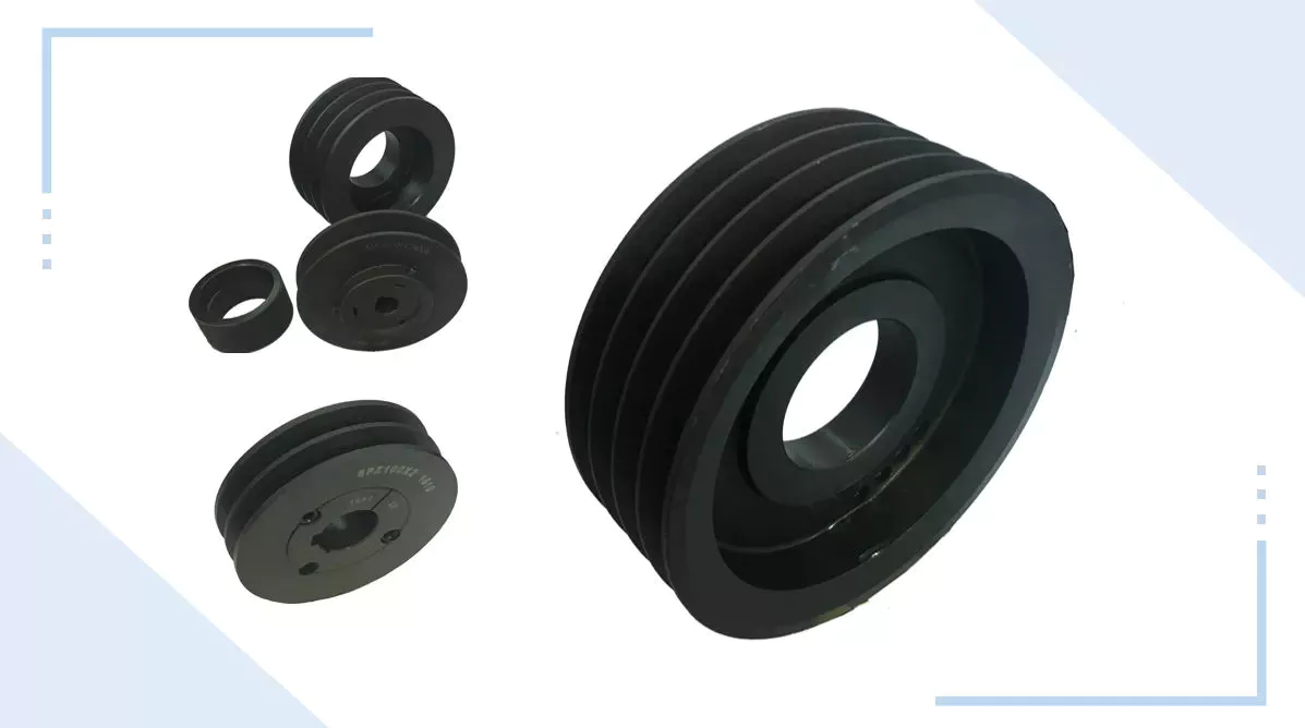
V-shaped pulleys are used in vehicles and electric motors. These pulleys require a “V” belt to function properly. Some have multiple “V” grooves to avoid slipping. They are used in heavy duty applications to reduce the risk of power slip. These pulleys also have more than 1 “V” groove. V-belt pulleys are commonly used in vehicles and electric motors.
Composite pulleys are made from more than 1 type of cable or rope wrapped around the wheel. They can be fixed or hinged and are usually made of stainless steel or bronze. Composite pulleys have multiple layers and can be a single unit or many different components. There are 3 main types of pulleys: fixed pulleys and composite pulleys. These are the most common types. Almost every type of pulley is used for some type of application.
Fixed pulleys have 1 advantage over movable pulleys: they change direction as the weight of the load increases. They are typically used in heavy construction equipment. Gun tackles, patio tackles, and stationary tackles are examples of equipment that use a pulley mechanism. These devices are very common and can be found on most modern construction sites. They provide great convenience for lifting large loads.

application

What are the applications of pulleys? Simply put, a pulley is a mechanical device that transforms a difficult task into an easier one. It consists of ropes and pulleys. It is usually used to lift objects. Usually, people wrap a rope around a pulley and pull up to lift the object. One disadvantage of using pulleys is that they require the same force as lifting the object directly.
One of the most popular applications of pulleys is lifting heavy objects. They help people pull up heavy objects and blocks. The system can also be used in seeders, lifts, grinders, etc. Other applications include raising flags, loading cargo, pulling curtains and rock or mountain climbing. Students can learn about the various uses of pulleys and the physics behind them.
Pulleys can be made of many different materials, depending on the application. Some are movable, which means they move with the object they are used to lift. This pulley system can be made of nylon, wire rope or fiber material. The best part about these systems is that they are easy to install and maintain. For a better grasp, use the guide or video tutorial to learn more about the pulley system and how it works.
Tapered pulleys are common in paper mills. They are high-quality pulleys that transmit power to connected parts. They can be dynamic or static and have different balances. Because pulley systems are highly customized, most industrial applications require systems designed specifically for specific applications. In this way, the system is safe, simple and inexpensive. The benefits of this design are endless.
The most common use of pulleys is for motor drives. They are used to minimize noise by applying force to the shaft to reduce the workload. They are also less expensive than gears and do not require lubrication. Furthermore, they can change the direction of the applied force. They are also less expensive than gears and are often used with other components. A screw is a cylindrical member with helical ribs used to connect something.
pulley

shortcoming

Although the pulley system makes it easier to move heavy objects, it still has some drawbacks. When using a pulley system, you must remember that the force required to lift the weight increases with the number of cycles. In addition, the distance between the puller and the heavy object increases, which may lead to accidents. Also, moving heavy objects can be tricky if the rope slips. Pulley systems are not very expensive and can be easily assembled. However, it does require a lot of space.
First, it is not efficient. Besides being inefficient, pulleys produce different forces at different speeds. Fixed pulleys use more force than the load, while movable pulleys move with the load. A movable pulley requires less force than a fixed pulley, but the combined system travels a long distance. Therefore, this method is not as efficient as the fixed method.
Pulleys are not only used in industrial processes. You can see them in various places in your daily life. For example, large construction cranes use pulleys to lift heavy loads. Even flagpoles, blinds, clotheslines, ziplines, motors and climbing equipment use pulleys. Still, despite their advantages, the disadvantages are not too serious.
Another disadvantage of the pulley is its wear and tear. While a pulley’s housing is theoretically infinite, its bearings and locking components typically wear out over time. To overcome this problem, a new bearing and locking assembly can be installed. No need to replace the housing and shaft, the entire assembly can be re-bonded and painted to replicate the original look. Alternatively, the pulley can be replaced with a new housing and shaft.
Using pulleys can also reduce the advantage of pulleys. On the other hand, interception and tackle is a system in which 2 pulleys are connected to each other using ropes. Unlike pulleys, pulley pulley systems can be adjusted in the direction of travel and can move heavy loads up to 4 times their force when used in hydraulic lifts.

China Best Sales Small 10tpd Combined Rice Mill Rice Milling Machine Parts     near me manufacturer China Best Sales Small 10tpd Combined Rice Mill Rice Milling Machine Parts     near me manufacturer

China Best Sales New Custom CNC Turning Milling Machine Component Metal Steel Aluminum CNC Precision Machining Part for Vehicle Auto Engine near me factory

Product Description

Basic Info
 

Surface treatment  polishing, chrome plating, zinc plating, nickel plating, clear/black anodizing, Black, Nitrogenation, sandblasting,  powder coating, etc.
Heat Treatment Nitride, Hardening etc.
Machining Equipment CNC Machining Center, CNC Turning Machine, CNC Milling Machine, Surface Grinders, Wire Cutting Machine,Electrical Discharge Machine,Drilling Machine, Rolling Machine
 
 
 Quality We have kind of measuring equipment like Coordinate Measuring Machine to check the pecision for the parts, and we will also make full protect for package for shipping. High Precision quality as drawing request will be provided.
 
Application Heavy industrial machinery, automation equipment, vehicles, package machines, food processing machines, agricultural machines, electronic machines, etc
Lead Time According to the quantity and drawings’ difficulties of clients
Trade Terms EXW, FOB, CIF, DAP.etc
Drawing Format . pdf / .dwg / .igs / .stp etc.

FAQ

Q1: Are you a trading company or a manufacturer? Location?
A1: We are a factory located in Bao’an, HangZhou, China.

Q2: Is there any MOQ required?
A2: No, there is no MOQ required, even 1 piece we can also process. 

Q3: How to ensure the quality of every process?
A3: The part will be checked when each process is finished, which makes sure there are no defects on the customers’ end.

Q4: How can I get the quotation?
A4: We will offer you the quotation within 12 working hours after receiving your detailed information. In order to quote you faster and more accurate, please provide us with the following information together with your inquiry:
1) CAD or 3D Drawings
2) Tolerance.
3) Material requirement
4) Surface treatment
5) Quantity (per order/per month/annual)
6) Any special demands or requirements, such as packing, labels, delivery, etc.

Q5: How do you make sure my drawings are confidential?
A5: we will keep them well and not release them to others without your permission. NDA can be also signed, if you needed.

Q6: Why choose HangZhou XYX Precision Co., Ltd?
A6:  1. Years of experience, which can offer you tailored solutions to your projects.
        2. Flexibility in lead time.
        3. Assurance in high-quality parts.


Helical, Straight-Cut, and Spiral-Bevel Gears

If you are planning to use bevel gears in your machine, you need to understand the differences between Helical, Straight-cut, and Spiral bevel gears. This article will introduce you to these gears, as well as their applications. The article will also discuss the benefits and disadvantages of each type of bevel gear. Once you know the differences, you can choose the right gear for your machine. It is easy to learn about spiral bevel gears.
gear

Spiral bevel gear

Spiral bevel gears play a critical role in the aeronautical transmission system. Their failure can cause devastating accidents. Therefore, accurate detection and fault analysis are necessary for maximizing gear system efficiency. This article will discuss the role of computer aided tooth contact analysis in fault detection and meshing pinion position errors. You can use this method to detect problems in spiral bevel gears. Further, you will learn about its application in other transmission systems.
Spiral bevel gears are designed to mesh the gear teeth more slowly and appropriately. Compared to straight bevel gears, spiral bevel gears are less expensive to manufacture with CNC machining. Spiral bevel gears have a wide range of applications and can even be used to reduce the size of drive shafts and bearings. There are many advantages to spiral bevel gears, but most of them are low-cost.
This type of bevel gear has 3 basic elements: the pinion-gear pair, the load machine, and the output shaft. Each of these is in torsion. Torsional stiffness accounts for the elasticity of the system. Spiral bevel gears are ideal for applications requiring tight backlash monitoring and high-speed operations. CZPT precision machining and adjustable locknuts reduce backlash and allow for precise adjustments. This reduces maintenance and maximizes drive lifespan.
Spiral bevel gears are useful for both high-speed and low-speed applications. High-speed applications require spiral bevel gears for maximum efficiency and speed. They are also ideal for high-speed and high torque, as they can reduce rpm without affecting the vehicle’s speed. They are also great for transferring power between 2 shafts. Spiral bevel gears are widely used in automotive gears, construction equipment, and a variety of industrial applications.

Hypoid bevel gear

The Hypoid bevel gear is similar to the spiral bevel gear but differs in the shape of the teeth and pinion. The smallest ratio would result in the lowest gear reduction. A Hypoid bevel gear is very durable and efficient. It can be used in confined spaces and weighs less than an equivalent cylindrical gear. It is also a popular choice for high-torque applications. The Hypoid bevel gear is a good choice for applications requiring a high level of speed and torque.
The Hypoid bevel gear has multiple teeth that mesh with each other at the same time. Because of this, the gear transmits torque with very little noise. This allows it to transfer a higher torque with less noise. However, it must be noted that a Hypoid bevel gear is usually more expensive than a spiral bevel gear. The cost of a Hypoid bevel gear is higher, but its benefits make it a popular choice for some applications.
A Hypoid bevel gear can be made of several types. They may differ in the number of teeth and their spiral angles. In general, the smaller hypoid gear has a larger pinion than its counterpart. This means that the hypoid gear is more efficient and stronger than its bevel cousin. It can even be nearly silent if it is well lubricated. Once you’ve made the decision to get a Hypoid bevel gear, be sure to read up on its benefits.
Another common application for a Hypoid bevel gear is in automobiles. These gears are commonly used in the differential in automobiles and trucks. The torque transfer characteristics of the Hypoid gear system make it an excellent choice for many applications. In addition to maximizing efficiency, Hypoid gears also provide smoothness and efficiency. While some people may argue that a spiral bevel gear set is better, this is not an ideal solution for most automobile assemblies.
gear

Helical bevel gear

Compared to helical worm gears, helical bevel gears have a small, compact housing and are structurally optimized. They can be mounted in various ways and feature double chamber shaft seals. In addition, the diameter of the shaft and flange of a helical bevel gear is comparable to that of a worm gear. The gear box of a helical bevel gear unit can be as small as 1.6 inches, or as large as 8 cubic feet.
The main characteristic of helical bevel gears is that the teeth on the driver gear are twisted to the left and the helical arc gears have a similar design. In addition to the backlash, the teeth of bevel gears are twisted in a clockwise and counterclockwise direction, depending on the number of helical bevels in the bevel. It is important to note that the tooth contact of a helical bevel gear will be reduced by about 10 to 20 percent if there is no offset between the 2 gears.
In order to create a helical bevel gear, you need to first define the gear and shaft geometry. Once the geometry has been defined, you can proceed to add bosses and perforations. Then, specify the X-Y plane for both the gear and the shaft. Then, the cross section of the gear will be the basis for the solid created after revolution around the X-axis. This way, you can make sure that your gear will be compatible with the pinion.
The development of CNC machines and additive manufacturing processes has greatly simplified the manufacturing process for helical bevel gears. Today, it is possible to design an unlimited number of bevel gear geometry using high-tech machinery. By utilizing the kinematics of a CNC machine center, you can create an unlimited number of gears with the perfect geometry. In the process, you can make both helical bevel gears and spiral bevel gears.

Straight-cut bevel gear

A straight-cut bevel gear is the easiest to manufacture. The first method of manufacturing a straight bevel gear was to use a planer with an indexing head. Later, more efficient methods of manufacturing straight bevel gears were introduced, such as the Revacycle system and the Coniflex system. The latter method is used by CZPT. Here are some of the main benefits of using a straight-cut bevel gear.
A straight-cut bevel gear is defined by its teeth that intersect at the axis of the gear when extended. Straight-cut bevel gears are usually tapered in thickness, with the outer part being larger than the inner portion. Straight-cut bevel gears exhibit instantaneous lines of contact, and are best suited for low-speed, static-load applications. A common application for straight-cut bevel gears is in the differential systems of automobiles.
After being machined, straight-cut bevel gears undergo heat treatment. Case carburizing produces gears with surfaces of 60-63 Rc. Using this method, the pinion is 3 Rc harder than the gear to equalize wear. Flare hardening, flame hardening, and induction hardening methods are rarely used. Finish machining includes turning the outer and inner diameters and special machining processes.
The teeth of a straight-cut bevel gear experience impact and shock loading. Because the teeth of both gears come into contact abruptly, this leads to excessive noise and vibration. The latter limits the speed and power transmission capacity of the gear. On the other hand, a spiral-cut bevel gear experiences gradual but less-destructive loading. It can be used for high-speed applications, but it should be noted that a spiral-cut bevel gear is more complicated to manufacture.
gear

Spur-cut bevel gear

CZPT stocks bevel gears in spiral and straight tooth configurations, in a range of ratios from 1.5 to five. They are also highly remachinable except for the teeth. Spiral bevel gears have a low helix angle and excellent precision properties. CZPT stock bevel gears are manufactured using state-of-the-art technologies and know-how. Compared with spur-cut gears, these have a longer life span.
To determine the strength and durability of a spur-cut bevel gear, you can calculate its MA (mechanical advantage), surface durability (SD), and tooth number (Nb). These values will vary depending on the design and application environment. You can consult the corresponding guides, white papers, and technical specifications to find the best gear for your needs. In addition, CZPT offers a Supplier Discovery Platform that allows you to discover more than 500,000 suppliers.
Another type of spur gear is the double helical gear. It has both left-hand and right-hand helical teeth. This design balances thrust forces and provides extra gear shear area. Helical gears, on the other hand, feature spiral-cut teeth. While both types of gears may generate significant noise and vibration, helical gears are more efficient for high-speed applications. Spur-cut bevel gears may also cause similar effects.
In addition to diametral pitch, the addendum and dedendum have other important properties. The dedendum is the depth of the teeth below the pitch circle. This diameter is the key to determining the center distance between 2 spur gears. The radius of each pitch circle is equal to the entire depth of the spur gear. Spur gears often use the addendum and dedendum angles to describe the teeth.

China Best Sales New Custom CNC Turning Milling Machine Component Metal Steel Aluminum CNC Precision Machining Part for Vehicle Auto Engine     near me factory China Best Sales New Custom CNC Turning Milling Machine Component Metal Steel Aluminum CNC Precision Machining Part for Vehicle Auto Engine     near me factory

China Good quality Cheap Price China +/-0.005 Qd Crate 230X120X35mm Ultrasonic Machine Cutting Car Accessories Spare Part near me shop

Product Description

HangZhou CZPT hardware machinery co., LTD mainly for the domestic and foreign customers to provide precision metal parts of intelligent manufacturing solutions, the company was founded in 2008, currently has more than 60 units, all kinds of high precision sophisticated equipment manufacturing system more than 80 employees, including senior technical personnel more than 40 people, and signed with the several technical and training center, talent directional delivery plan.
  The company’s business involves the precision parts and hardware processing of auto parts, 3C automation equipment, aerospace, engineering machinery, medical, food, new energy battery equipment, instruments and meters, precision instruments, hardware tools and other industries.  At the same time, we also provide customers with precision fixture, fixture, mold parts design and manufacturing, special material parts processing (such as ceramics, hard alloy) and automation equipment design, installation, commissioning, and production equipment maintenance, improvement and other related business.  
In terms of production, we comply with ISO9001:  2015 quality management system, each link of production strictly control, to ensure product performance and quality, at the same time the company also set up the system perfect, the internationalization of scientific and effective information security management system, from the professional and authority level for the customer to provide information security, let the customer’s product won’t appear the leaks of security risks, make guaranteed delivery cycle.  

Companies adhering to the “heavy quality, honest, responsible” corporate purposes, with “customer first, in the victory in technology, efficiency and win in the service” business philosophy, in the “fine management, skilled, profound culture, team capable” of the “four” management policy guidance, the company has been in the precision parts processing industry has reached the industry leading level.  

At present, the company has served nearly 100 customers, 80% of the customers are well-known enterprises in the industry, at the same time, we have a perfect after-sales service system in the industry, continue to use a solid technical basis and strict scientific management system, continuous improvement, beyond customer satisfaction, so that customers feel comfortable before cooperation, after cooperation.  

    Service  service item
Product  Service CNC turning parts/ Machining 
CNC milling  parts machining 
 simple CNC turning-milling product
 4-Axis  turning-milling combined machining product
 high precision  5-Axis  turning-milling combined machining product
customzied Machine tools, metal machining – parts and accessories
Precison CNC PRECISION AUTOMATIC LATHE product
CNC Swiss screw machine parts
Centerless  grinding services
Product quality Inspection Service Inspection Report
First Article Inspection


A: We are a professional manufacturer of precision parts.

Q2. What are your payment terms?
A: T/T 50% is used as a deposit, and the remaining 50% is used as a copy of BL.

Q3. What are your delivery terms?
A: EXW, FOB, CFR, CIF, DDU.

Q4. How is your delivery time?
A: We can ship the order within 3-30 days, depending on the quantity.

Q5. Can you produce according to samples?
A: Yes, we can produce according to your samples or technical drawings. We can make new molds.

Q6. What is your sample policy?
A: If we have stock, we can provide samples, but the customer must pay the sample cost and
Courier fees.

Q7. Do you test all the goods before delivery?
A: Yes, we have testing machines and QC workers to do the testing.

Q8: How do you make our business a long-term good cooperative relationship?
Answer: 1. We maintain excellent quality and competitive prices to ensure that our customers benefit;
2. We respect every customer as our friend, we do business sincerely, make friends,
No matter where they are from.
 

Choosing the Right Ball Bearing for Your Application

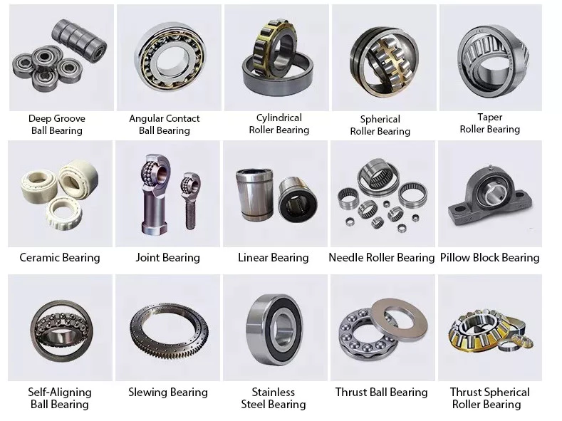
When choosing a Ball Bearing, there are several things to consider. These factors include: the size, lubricant type, presence of corrosive agents, stray electrical currents, and more. It can be challenging to choose the right type, size, and type of ball bearing for your application. You should also carefully calculate the loads to determine the right size. Here are some tips for choosing the right Ball Bearing for your application.

Single-row

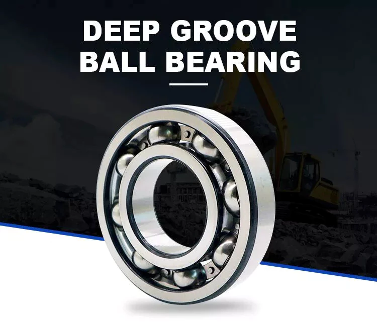
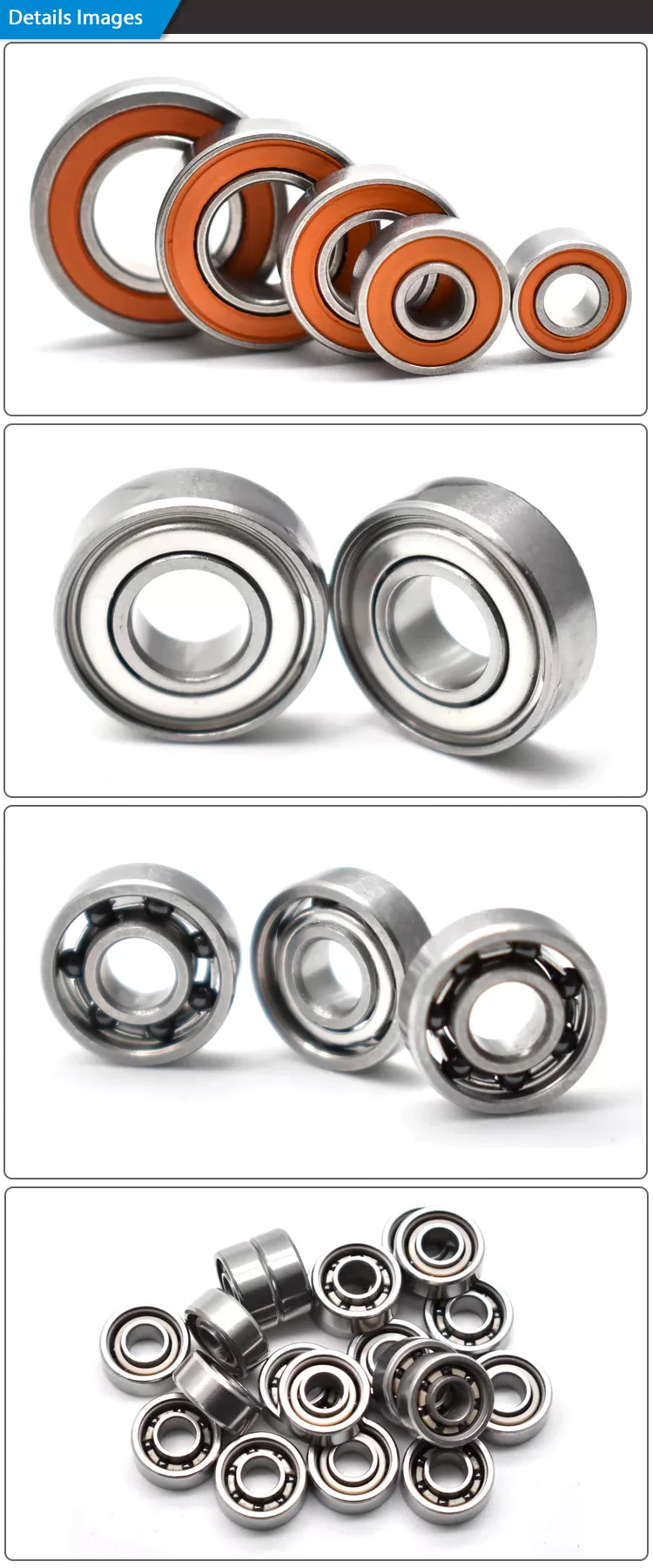
The single-row ball bearing is 1 of the most popular types of bearings. The inner and outer ring are designed with raceway grooves that are shaped slightly larger than the balls. This type of bearing has a low torque and can handle high-speed applications with minimal power loss. The radial dimensions of single-row ball bearings also vary, so it is possible to find 1 that fits your specific application. Besides the above-mentioned advantages, single-row ball bearings are also available with varying grease levels and are widely applicable to applications where the space is limited.
Single-row ball bearings are also called angular-contact ball bearings. Because of their single-row design, they are not separable and can accommodate a high-speed, heavy-duty application. Single-row angular-contact ball bearings can only handle axial load in 1 direction, and they must be installed in pairs for pure radial loads. Single-row ball bearings are a popular type of rolling bearings and can be used for a wide range of applications.
bearing

Self-aligning

The self-aligning ball bearing was invented by Sven Wingquist, a plant engineer for a textile company in Sweden. While he was responsible for making production as efficient as possible, he soon realized that the machinery he had in place wasn’t working as efficiently as it could. Although ball bearings are great for reducing friction, they were not flexible enough to compensate for misalignments in the machine.
Self-aligning ball bearings have 2 rows of balls and a common sphered raceway. The inner ring is curved and combines the 2 rows of balls into 1 cage. These bearings can tolerate shaft misalignment and compensate for static angular defects. They can be used in simple woodworking machinery, ventilators, and conveying equipment. They are often the preferred choice for applications where shaft alignment is an issue.

Ceramic

A Ceramic ball bearing is a type of high-performance bearing that is available in both full-ceramic and hybrid forms. The main differences between ceramic and steel ball bearings are their construction, lubrication, and mobility. High-quality ceramic ball bearings are durable, and they are ideal for corrosive and high-temperature applications. The material used to create these bearings helps prevent electrolytic corrosion. They are also ideal for reducing the friction and lubrication requirements.
Ceramic balls are harder and less brittle than steel balls, which gives them a higher degree of rigidity. Ceramics also have a higher hardness, with a hardness of Rc75-80 compared to Rc58-64 for steel balls. Their high compressive strength is approximately 5 to 7 times greater than steel. In addition, they have a very low coefficient of friction, which allows them to spin at higher speeds and with less friction. This increases their lifespan and durability, and decreases the energy needed to turn cranks.

Steel

Unlike traditional bearings, steel balls have a relatively uniform hardness. Carbon steel, for instance, is 2.1% carbon by weight. According to the American Iron and Steel Institute, copper content must be no more than 0.40% and manganese content should not be more than 1.65 g/cm3. After carbonizing, steel balls undergo a process called sizing, which improves their roundness geometry and hardness.
The main differences between steel ball bearings and ceramic ball bearings can be traced to their different materials. Ceramic balls are made from zirconium dioxide or silicon nitride. Silicon nitride is harder than steel and resists shocks. The result is increased speed and longer service life. Polyoxymethylene acetal (PMMA) bearing balls are known for their stiffness, strength, and tolerance, but are not as common as steel ball bearings.

Plastic

The most popular types of plastic ball bearings are made of polypropylene or PTFE. These bearings are used in applications requiring higher chemical resistance. Polypropylene is a structural polymer that offers excellent physical and chemical properties, including excellent resistance to organic solvents and degreasing agents. Its lightweight, low moisture absorption rate, and good heat resistance make it an excellent choice for high-temperature applications. However, plastic bearings are not without their drawbacks, especially when operating at very high temperatures or under heavy loads.
Compared to metal bearings, plastic ball-bearings do not require lubrication. They also are highly corrosion-resistant, making them an excellent choice for wash-down applications. They are also post-, autoclave-, and gamma sterilizable. Many conventional steel ball-bearings cannot handle the high temperatures of food processing or swimming pools. In addition to high temperature applications, plastic ball bearings are resistant to chemicals, including chlorine.
bearing

Glass

Plastic sliding bearings are molded bearings made of engineering plastic. With self-lubricating modification technology, these bearings can be produced by injection molding of plastic beads. They are widely used in various industries such as office equipment, fitness and automotive equipment. In addition to plastic bearings, glass balls are used in a variety of other applications, including medical equipment. Glass ball bearings have excellent corrosion resistance, excellent mechanical properties, and are electrically insulators.
Plastic ball bearings are made of all-plastic races and cages. These bearings are suitable for applications that are exposed to acids and alkalis. Because they are cheaper than glass balls, plastic ball bearings are popular in chemical-exposed environments. Stainless steel balls are also resistant to heat and corrosion. But the main disadvantage of plastic ball bearings is that they are not as strong as glass balls. So, if weight and noise is your main concern, consider using plastic balls instead.

Miniature

The global miniature ball bearing market is expected to reach US$ 2.39 Billion by 2027, at a CAGR of 7.2%. Growth in the region is attributed to technological advancement and government initiatives. Countries such as India and China are attracting FDIs and emphasizing the establishment of a global manufacturing hub. This is boosting the market for miniature ball bearings. The miniscule ball bearings are manufactured in small quantities and are very small.
Some manufacturers produce miniature ball bearings in different materials and designs. Chrome steel is the most popular material for miniature ball bearings because of its high load capacity, low noise properties, and lower cost. But the cost of stainless steel miniature bearings is low, since the amount of steel used is minimal. Stainless steel miniature bearings are the smallest in size. Therefore, you can choose stainless steel mini ball bearings for high-speed applications.

Angular-contact

Angular-contact ball bearings have 3 components: a cage, inner ring, and balls. Angular-contact ball bearings can support high axial and radial loads. Various design and manufacturing attributes make angular-contact ball bearings suitable for a variety of applications. Some features of this bearing type include a special lubricant, different cage materials, and different coatings.
The size of an angular-contact ball bearing is determined by the design units: outer ring width, axial load, and radial load. Depending on the type of application, an angular-contact ball bearing may be manufactured in double-row, triple-row, or quadruple-row configurations. Angular contact ball bearings can be classified according to their design units, which range from metric to imperial. A higher ABEC number means tighter tolerances. To determine the tolerance equivalent of a particular bearing, consult a standard Angular-contact ball bearing table.
Angular-contact ball bearings feature high and low-shoulder configurations. They have two-dimensional races that accommodate axial and radial loads. They are available in self-retaining units with solid inner and outer rings, and ball and cage assemblies. Cages made of cast and wrought brass are the most popular, but lightweight phenolic cages are also available. The latter is a better choice because it doesn’t absorb oil and has lower rolling friction.
bearing

Materials

When it comes to the construction of a ball bearing, high-quality raw materials are a crucial component. These materials not only affect the overall quality of a ball bearing, but also influence the cost. That’s why you should pay close attention to raw material quality. In addition to that, raw materials should be tested several times before the manufacturing process to ensure quality. Read on for some information about the different types of materials used to make ball bearings.
Steel is the most common material for ball bearings. Most ball bearings contain stainless steel balls, which are remarkably corrosion-resistant. They are also resistant to saltwater and alkalis. However, stainless steel balls are heavier than plastic ones, and they are also magnetic, which may be a drawback in some applications. If you’re looking for a metal-free option, glass balls are the way to go. They’re sturdy, lightweight, and resistant to a wide range of chemicals.

China Good quality Cheap Price China +/-0.005 Qd Crate 230X120X35mm Ultrasonic Machine Cutting Car Accessories Spare Part     near me shop China Good quality Cheap Price China +/-0.005 Qd Crate 230X120X35mm Ultrasonic Machine Cutting Car Accessories Spare Part     near me shop

China high quality Good Service Milling Parts Aluminum Machine Auto Spare Motorcycle CNC Machining Part with Good quality

Product Description

HangZhou CZPT Hardware Machinery Co., Ltd. mainly provides intelligent manufacturing solutions for precision hardware parts for domestic and foreign customers. The company was established in 2008 and currently has more than 60 sets of various high-precision cutting-edge equipment and more than 80 employees in the production system, including There are more than 40 senior technical talents, and a talent directional transfer plan has been signed with a number of technical schools and training centers.
 
The company’s business involves precision parts and hardware processing in many industries such as auto parts, 3C automation equipment, aerospace, construction machinery, medical, food, new energy battery equipment, instrumentation, precision instruments, hardware tools, etc. At the same time, it also provides customers with precision parts. Design and manufacture of fixtures, jigs, mold accessories, processing of special material parts (such as ceramics, cemented carbide) and automation equipment design, installation, debugging, and production equipment maintenance, improvement and other related businesses.

In terms of production, according to the ISO9001:2015 quality management system, we strictly control each link of product production to ensure product performance and quality. At the same time, the company has also established a systematic, scientific and effective international information security management system, from professional And authoritative level to provide customers with information security, so that customers’ products will not have security risks of leakage, so that the delivery cycle is guaranteed.

The company adheres to the corporate tenet of “emphasis on quality, integrity, and responsibility”, with the business philosophy of “customer first, technology, efficiency, and service”. Under the guidance of the “Four Fines” business policy, the company has reached the forefront of the industry in the entire precision parts processing industry.

At present, the company has served nearly 100 customers, 80% of which are well-known enterprises in the industry. At the same time, we have a perfect after-sales service system in the industry, and continue to use a solid technical foundation and strict scientific management system to continuously improve and surpass Customer satisfaction, so that customers feel comfortable before cooperation and rest assured after cooperation.

Our advantage of cnc machining:
 

Business Type

Manufacturer


Advantage

1. Qida is factory providing CNC machining service for more than 10years, we focus on client’s demand and client’s satisfaction.

2. Provide 2D & 3D drawing for modifying

3. Competitive price with good quality

4. Small order is acceptable

5. Short delivery time (7-25days according to order Qty)

6. Customized size and specification /OEM available

7. Near HangZhou and HangZhou, convenient transportation


Application

.Automobile, motorcycle, medical machinery, electronics, fixtures, automation, etc


Materials Available of CNC Machining:


Materials Available


Stainless Steel

SS201, SS303, SS304, SS316 etc.

Steel

Q235, 20#, 45# etc.cr12mor, 


Brass

C36000 ( C26800), C37700 ( HPb59), C38500( HPb58), C27200(CuZn37) , C28000(CuZn40)

Iron:

1213, 12L14,1215 etc.

Bronze

C51000, C52100, C54400, etc.

Aluminum

Al6061, Al6063,AL7075,AL5052 etc

Better services of CNC machining:

(Payment Terms/Trade Term/Shipment Terms/ ):

Our Processing

CNC machining, CNC milling and turning, drilling, grinding, bending, stamping, tapping, injection
Wire cut

Surface finish

Zinc-plated, nickel-plated, chrome-plated, silver-plated, gold-plated, imitation gold-plated,

Tolerance

0.05mm~0.1mm

QC System

100% inspection before shipment

Drawing format

CAD / PDF/ DWG/ IGS/ STEP

Packaging

Standard package / Carton or Pallet / As per customized specifications

Payment Terms

30 -50%T/T in advance, 70-50% balance before delivery; Pay Pal or Western Union is acceptable.

Trade terms

EXW, FOB, CIF, As per customer’s request


Shipment Terms

1) 0-100kg: express & air freight priority

2) >100kg: sea freight priority

3) As per customized specifications


Note

All cnc machining parts are custom made according to customer’s drawings or samples, no stock.

If you have any cnc machining parts to be made, please feel free to send your kind drawings/samples to us

FAQ:
What is your product range?
1.CNC machining parts, precision parts, CNC parts, metal machining parts.
2.CNC turning parts, CNC turned parts,Lathe parts, turned parts.
3.CNC milling parts, CNC milled parts, metal milling parts.
4.CNC machined parts,CNC machine part, CNC machinery parts.
5.Metal parts, Auto parts, mechanical parts.spare parts,accessories,hardware.
6.Die casting parts,aluminum casting parts, Zinc casting parts.
7.Die stamping parts, metal stamping parts, press stamping tooling
8. Sheet metal fabrication, bending parts, laser cutting parts, welding parts.
 
Are you a manufacturer?
Yes, We are the manufacturer of all kinds of metal parts by CNC machining, turning, milling, stamping,
casting and bending with13 years’experince ,Warmly welcome to visit our factory at any time.
 
What is material you can process?
Stainless steel: SUS303, SUS304, SUS316, SUS316L, SUS430, SUS440, etc
Aluminum: 6061-T6, 6063-T5, 7075-T6, 2011, 2017, 2571, 5052, 5083, 6082 etc
Brass/copper: C11000, C15710, C12000, C26000, C36000, etc
Carbon steel:  Q235,S235JR,1571, 1015, 1571, 1571, 1030, 1035, 1040, 1045, etc
Plastic: PVC, POM, Telfon, Delrin, PEEK ,Nylon, ABS, PC, PP,PA6, PA66, etc
Free cutting steel: 1211, 12L13, 12L14, 1215, etc
Tool Steel: SKD61,SKD11,HSS M2,ASP23 ,H13,1.2344,D2,1.2379,etc
Alloy steel: 40Cr,15CrMo,4140,4340,35CrMo,16MnCr5
Titanium alloy
 
What benefit we can get from you?
1)Competitive price
2)High quality control : 100% full inspection before shipment
3)High precision, tolerance can be ± 0.005mm
4)Fast lead time (5-7days for samples, 12-15 days for mass production)
5)Non-standard//OEM//customized service provided
6)No MOQ, small QTY is acceptable.
7)ISO 9001:2015 certificated factory, ROHS material used
9)Professional export packing: separate Blister plastic box or Bubble Wrap/Pearl Wool +Carton+Wooded Case, keep no scratch and damage
 
How does the CZPT control the quality?
1)During processing, the operating machine worker inspect the each sizes by themselves.
2)After finished the first whole part, will show to QA for full inspection.
3)Before shipment, the QA will inspect according to ISO sampling inspection standard for mass production. Will do 100% full checking for small QTY.
4) when shipping the goods, we will attached the inspection report with the parts.
 
How to handle the complains?
1)During processing, if found any sizes defective, we will inform the clients and get clients approval.
2)If happen any complaints after got the goods, pls show us photos and detail complaints points, we will check with the production department and QC depart. Immediately and give solving solution with 6 hours.
3)If need re-make, we will arrange re-make urgently and ship you new replacement within 5 days. CZPT will bear all the cost ( include shipping cost).
 
What’s the payment term?
50% deposit, 50% balance by T/T before shipment when order amount over 5000USD.
100% T/T in advance when amount less than 5000USD
L/C payment term for big amount order is acceptable.
Paypal and Western Union for samples cost or very small order.
 
 
What’s the delivery time ?
Normal for samples, 5-7 working days;
For mass production, it takes about 12-15 working days.
If any urgent parts, we can provide preferential processing and control the delivery time as you required.
 
What is the standard of package?
Professional export packing:
1)Separate Blister plastic box or Bubble Wrap/Pearl Wool, keep no scratch and damage.
2)Under 100 KGS parts, use strong DHL export Carton .
3)Above 100 KGS, will customize Wooded case for packing.
 
How to ship the parts?
1)Normally, we shipped the goods by DHL,FEDEX,UPS,TNT express.
2-3 days can arrived the clients’ company directly.
2)For heavy parts, can shipped by air or by sea according to customers’indication.
 
Can we get some sample?
1.Free sample can be provided,but the clients will bear the shipping cost.
2.Samplemaking can be satisfied as customer’s demands,and the sample cost is about 50-100 USD for each part,it depends on the processing.
3. Sample charge is returnable after order the mass production.
 
What kind of certificate you have ?
We have ISO9001:2015
RoHS compliance for material and surface treatment
 
What information should i let you know once i want to make a inquiry?
1.The drawings ( PDF,CAD or 3D )?
2. The material for each drawings?
3. The surface treatment requirement.
4. How many pieces do you need?
 
How fast you can get quotation from CZPT ?
After get customer’s detail enquiry( Clear drawings, material, QTY, surface treatment).
Normally, we will provide offer within 6 hours.
If more than 100 drawings, will provide price within 24 hours.
 
What is your main market?
North America, South America, Western European,
Southeast Asia,Australia


Spiral Gears for Right-Angle Right-Hand Drives

Spiral gears are used in mechanical systems to transmit torque. The bevel gear is a particular type of spiral gear. It is made up of 2 gears that mesh with 1 another. Both gears are connected by a bearing. The 2 gears must be in mesh alignment so that the negative thrust will push them together. If axial play occurs in the bearing, the mesh will have no backlash. Moreover, the design of the spiral gear is based on geometrical tooth forms.
Gear

Equations for spiral gear

The theory of divergence requires that the pitch cone radii of the pinion and gear be skewed in different directions. This is done by increasing the slope of the convex surface of the gear’s tooth and decreasing the slope of the concave surface of the pinion’s tooth. The pinion is a ring-shaped wheel with a central bore and a plurality of transverse axes that are offset from the axis of the spiral teeth.
Spiral bevel gears have a helical tooth flank. The spiral is consistent with the cutter curve. The spiral angle b is equal to the pitch cone’s genatrix element. The mean spiral angle bm is the angle between the genatrix element and the tooth flank. The equations in Table 2 are specific for the Spread Blade and Single Side gears from Gleason.
The tooth flank equation of a logarithmic spiral bevel gear is derived using the formation mechanism of the tooth flanks. The tangential contact force and the normal pressure angle of the logarithmic spiral bevel gear were found to be about 20 degrees and 35 degrees respectively. These 2 types of motion equations were used to solve the problems that arise in determining the transmission stationary. While the theory of logarithmic spiral bevel gear meshing is still in its infancy, it does provide a good starting point for understanding how it works.
This geometry has many different solutions. However, the main 2 are defined by the root angle of the gear and pinion and the diameter of the spiral gear. The latter is a difficult 1 to constrain. A 3D sketch of a bevel gear tooth is used as a reference. The radii of the tooth space profile are defined by end point constraints placed on the bottom corners of the tooth space. Then, the radii of the gear tooth are determined by the angle.
The cone distance Am of a spiral gear is also known as the tooth geometry. The cone distance should correlate with the various sections of the cutter path. The cone distance range Am must be able to correlate with the pressure angle of the flanks. The base radii of a bevel gear need not be defined, but this geometry should be considered if the bevel gear does not have a hypoid offset. When developing the tooth geometry of a spiral bevel gear, the first step is to convert the terminology to pinion instead of gear.
The normal system is more convenient for manufacturing helical gears. In addition, the helical gears must be the same helix angle. The opposite hand helical gears must mesh with each other. Likewise, the profile-shifted screw gears need more complex meshing. This gear pair can be manufactured in a similar way to a spur gear. Further, the calculations for the meshing of helical gears are presented in Table 7-1.
Gear

Design of spiral bevel gears

A proposed design of spiral bevel gears utilizes a function-to-form mapping method to determine the tooth surface geometry. This solid model is then tested with a surface deviation method to determine whether it is accurate. Compared to other right-angle gear types, spiral bevel gears are more efficient and compact. CZPT Gear Company gears comply with AGMA standards. A higher quality spiral bevel gear set achieves 99% efficiency.
A geometric meshing pair based on geometric elements is proposed and analyzed for spiral bevel gears. This approach can provide high contact strength and is insensitive to shaft angle misalignment. Geometric elements of spiral bevel gears are modeled and discussed. Contact patterns are investigated, as well as the effect of misalignment on the load capacity. In addition, a prototype of the design is fabricated and rolling tests are conducted to verify its accuracy.
The 3 basic elements of a spiral bevel gear are the pinion-gear pair, the input and output shafts, and the auxiliary flank. The input and output shafts are in torsion, the pinion-gear pair is in torsional rigidity, and the system elasticity is small. These factors make spiral bevel gears ideal for meshing impact. To improve meshing impact, a mathematical model is developed using the tool parameters and initial machine settings.
In recent years, several advances in manufacturing technology have been made to produce high-performance spiral bevel gears. Researchers such as Ding et al. optimized the machine settings and cutter blade profiles to eliminate tooth edge contact, and the result was an accurate and large spiral bevel gear. In fact, this process is still used today for the manufacturing of spiral bevel gears. If you are interested in this technology, you should read on!
The design of spiral bevel gears is complex and intricate, requiring the skills of expert machinists. Spiral bevel gears are the state of the art for transferring power from 1 system to another. Although spiral bevel gears were once difficult to manufacture, they are now common and widely used in many applications. In fact, spiral bevel gears are the gold standard for right-angle power transfer.While conventional bevel gear machinery can be used to manufacture spiral bevel gears, it is very complex to produce double bevel gears. The double spiral bevel gearset is not machinable with traditional bevel gear machinery. Consequently, novel manufacturing methods have been developed. An additive manufacturing method was used to create a prototype for a double spiral bevel gearset, and the manufacture of a multi-axis CNC machine center will follow.
Spiral bevel gears are critical components of helicopters and aerospace power plants. Their durability, endurance, and meshing performance are crucial for safety. Many researchers have turned to spiral bevel gears to address these issues. One challenge is to reduce noise, improve the transmission efficiency, and increase their endurance. For this reason, spiral bevel gears can be smaller in diameter than straight bevel gears. If you are interested in spiral bevel gears, check out this article.
Gear

Limitations to geometrically obtained tooth forms

The geometrically obtained tooth forms of a spiral gear can be calculated from a nonlinear programming problem. The tooth approach Z is the linear displacement error along the contact normal. It can be calculated using the formula given in Eq. (23) with a few additional parameters. However, the result is not accurate for small loads because the signal-to-noise ratio of the strain signal is small.
Geometrically obtained tooth forms can lead to line and point contact tooth forms. However, they have their limits when the tooth bodies invade the geometrically obtained tooth form. This is called interference of tooth profiles. While this limit can be overcome by several other methods, the geometrically obtained tooth forms are limited by the mesh and strength of the teeth. They can only be used when the meshing of the gear is adequate and the relative motion is sufficient.
During the tooth profile measurement, the relative position between the gear and the LTS will constantly change. The sensor mounting surface should be parallel to the rotational axis. The actual orientation of the sensor may differ from this ideal. This may be due to geometrical tolerances of the gear shaft support and the platform. However, this effect is minimal and is not a serious problem. So, it is possible to obtain the geometrically obtained tooth forms of spiral gear without undergoing expensive experimental procedures.
The measurement process of geometrically obtained tooth forms of a spiral gear is based on an ideal involute profile generated from the optical measurements of 1 end of the gear. This profile is assumed to be almost perfect based on the general orientation of the LTS and the rotation axis. There are small deviations in the pitch and yaw angles. Lower and upper bounds are determined as – 10 and -10 degrees respectively.
The tooth forms of a spiral gear are derived from replacement spur toothing. However, the tooth shape of a spiral gear is still subject to various limitations. In addition to the tooth shape, the pitch diameter also affects the angular backlash. The values of these 2 parameters vary for each gear in a mesh. They are related by the transmission ratio. Once this is understood, it is possible to create a gear with a corresponding tooth shape.
As the length and transverse base pitch of a spiral gear are the same, the helix angle of each profile is equal. This is crucial for engagement. An imperfect base pitch results in an uneven load sharing between the gear teeth, which leads to higher than nominal loads in some teeth. This leads to amplitude modulated vibrations and noise. In addition, the boundary point of the root fillet and involute could be reduced or eliminate contact before the tip diameter.

China high quality Good Service Milling Parts Aluminum Machine Auto Spare Motorcycle CNC Machining Part     with Good qualityChina high quality Good Service Milling Parts Aluminum Machine Auto Spare Motorcycle CNC Machining Part     with Good quality

China Best Sales Automation Equipment, Automobile Industry Aluminum China Stainless Steel Brake Shoe Machine Lianhuashan Car Parts in with Good quality

Product Description

HangZhou CZPT Hardware Machinery Co., Ltd. mainly provides intelligent manufacturing solutions for precision hardware parts for domestic and foreign customers. The company was established in 2008. At present, it has more than 60 sets of various high-precision cutting-edge equipment and more than 80 employees in the production system, including There are more than 40 senior technical talents, and a talent directional transfer plan has been signed with a number of technical schools and training centers.

The company’s business involves precision parts and hardware processing in many industries such as auto parts, 3C automation equipment, aerospace, construction machinery, medical, food, new energy battery equipment, instrumentation, precision instruments, hardware tools, etc. At the same time, it also provides customers with precision parts. Design and manufacture of fixtures, jigs, mold accessories, processing of special material parts (such as ceramics, cemented carbide) and automation equipment design, installation, debugging, and production equipment maintenance, improvement and other related businesses.
In terms of production, according to the ISO9001:2015 quality management system, we strictly control each link of product production to ensure product performance and quality. At the same time, the company has also established a systematic, scientific and effective international information security management system, from professional And authoritative level to provide customers with information security, so that customers’ products will not have security risks of leakage, so that the delivery cycle is guaranteed.
The company adheres to the corporate tenet of “emphasis on quality, integrity, and responsibility”, with the business philosophy of “customer first, technology, efficiency, and service”. Under the guidance of the “Four Fines” business policy, the company has reached the forefront of the industry in the entire precision parts processing industry.

Our advantage of cnc machining:

Business Type

Manufacturer


Advantage

1. Qida is factory providing CNC machining service for more than 10years, we focus on client’s demand and client’s satisfaction.

2. Provide 2D & 3D drawing for modifying

3. Competitive price with good quality

4. Small order is acceptable

5. Short delivery time (7-25days according to order Qty)

6. Customized size and specification /OEM available

7. Near HangZhou and HangZhou, convenient transportation


Application

.Automobile, motorcycle, medical machinery, electronics, fixtures, automation, etc


Better services of CNC machining:

(Payment Terms/Trade Term/Shipment Terms/ ):

Our Processing

CNC machining, CNC milling and turning, drilling, grinding, bending, stamping, tapping, injection
Wire cut

Surface finish

Zinc-plated, nickel-plated, chrome-plated, silver-plated, gold-plated, imitation gold-plated,

Tolerance

0.05mm~0.1mm

QC System

100% inspection before shipment

Drawing format

CAD / PDF/ DWG/ IGS/ STEP

Packaging

Standard package / Carton or Pallet / As per customized specifications

Payment Terms

30 -50%T/T in advance, 70-50% balance before delivery; Pay Pal or Western Union is acceptable.

Trade terms

EXW, FOB, CIF, As per customer’s request


Shipment Terms

1) 0-100kg: express & air freight priority

2) >100kg: sea freight priority

3) As per customized specifications


Note

All cnc machining parts are custom made according to customer’s drawings or samples, no stock.

If you have any cnc machining parts to be made, please feel free to send your kind drawings/samples to us

All products with mark label.
We take pictures for each order then email to customers.
We track all shipping processes
Any quality problem that we will deal it in the first time as soon as possible

The first quarter. Are you the factory of a trading company?
A: We are a professional manufacturer of precision parts.

Q2. What are your payment terms?
A: T/T 50% is used as a deposit, and the remaining 50% is used as a copy of BL.

Q3. What are your delivery terms?
A: EXW, FOB, CFR, CIF, DDU.

Q4. How is your delivery time?
A: We can ship the order within 3-30 days, depending on the quantity.

Q5. Can you produce according to samples?
A: Yes, we can produce according to your samples or technical drawings. We can make new molds.

Q6. What is your sample policy?
A: If we have stock, we can provide samples, but the customer must pay the sample cost and
Courier fees.

Q7. Do you test all the goods before delivery?
A: Yes, we have testing machines and QC workers to do the testing.

Q8: How do you make our business a long-term good cooperative relationship?
Answer: 1. We maintain excellent quality and competitive prices to ensure that our customers benefit;
2. We respect every customer as our friend, we do business sincerely, make friends,
No matter where they are from.


What makes pulleys so important?

A pulley is a simple tool that makes it easy to lift or move heavy objects. There are many uses for this tool, but let’s take a look at their mechanical advantages. There are several types and many applications, along with their benefits and costs. So what makes them so important? Read on to find out! Below are some of the most common uses for pulleys. Let’s dive into them.
pulley

Mechanical advantage

If you’ve ever used rope and pulley systems, you’ve probably noticed their usefulness. A 3:1 mechanical advantage system is like a 300-pound load being moved 1 foot up by 3 feet of rope. Then you can imagine using the same rope to get into a small space. The same principle applies to limited spaces, and a simple mechanical advantage system is just what you need for this purpose.
Assuming frictionless bearings, a single movable pulley can have 2 mechanical advantages. It is attached to a heavy object and requires the pulling force exerted by the jack to lift the heavy object. However, when you use a compound pulley, the force exerted on the rope to lift the object changes direction. The 3 factors used to measure machine efficiency are force, distance, and relative motion.
The mechanical advantage of the pulley is that it reduces the effort required to lift weights. When the rope is attached to the 2 wheels, applying a force of 500 Newtons can lift a mass of 100 kg. This mechanical advantage is why 2 rings in a pulley are better than one. Therefore, using a pulley system will save you energy. You can also use branches instead of ropes and pulleys.

type

There are several different types of pulleys. They can be simple or complex, depending on how they are connected. Simple pulleys have a grooved wheel on 1 end and are attached to an axle. These pulleys are used to lift heavy objects. They are often found on sailboats, and you can even see them on construction sites. On the other hand, stationary pulleys are attached to stationary structures, such as flagpoles. Fixed pulleys can also be used to lift loads from trucks or trains. Pulleys are also commonly used in wells.
Fixed pulley systems use rollers or single wheels. These pulleys are usually made of nylon or wire rope. They are used in heavy duty applications. They are also used in electric motors. A “V” pulley requires a “V” belt to transmit power. Some of these pulleys have multiple “V” grooves to reduce the risk of power slipping. Once installed, fixed pulleys are suitable for many applications.
Simple pulleys are simple pulleys. It has a pulley mounted on an axle and a rope at 1 end. Rope can be used to pull objects, while plastic pulleys can carry lighter loads. There are 2 main types: heavy duty and simple pulley systems. In either case, their function is the same: they change the direction in which the seat belt is fastened. So when comparing the two, it’s easy to decide which 1 is best for you.
pulley

application

Pulley systems are simple machines used for a variety of industrial and mechanical tasks. Its design parameters and benefits have improved over the years, but they remain essential for many applications. Let’s take a look at some of the most common applications of pulleys. The applications for pulley systems are endless, from construction to mining, from transportation to packaging. Read on to learn more!
Pulley systems are often used to lift large objects, such as blocks, that might otherwise be too heavy to lift. It also makes the exploration process easier by helping people pull heavy objects into place. It is also widely used on sailing ships. Due to its low cost of use and no need for lubrication, it is a practical choice for many applications. It can be used to lift heavy objects and support long ropes.
The pulley system allows you to change the force required to move the object. For example, a two-wheel pulley system is especially useful for reducing the effort required to lift large objects. The mechanical advantage increases with the number of wheels in the system. In addition, the mechanical advantage of a two-wheel pulley system depends on the ratio of the load weight to the number of rope segments in the system.

cost

In most cases, an idler replacement will cost around $150, but the exact cost will depend on several factors, including the make and model of the car. The cost also depends on the type of idler you need and the cost of the OEM parts. Some pulleys are easy to replace at home, while others require specialized tools, such as pulley wrenches. The chart below shows the cost of popular vehicles. Prices are valid at the time of writing.
The diameter of the pulley is also important, this should be about 60% of the diameter of the active pulley. You can also purchase compensating pulleys at factory prices. Be sure to select the correct size before placing the pulley on the machine. Also, make sure you have enough space for the pulleys. Once you have the desired pulley size, you can determine the best type of belt to install.
While this method is the most common type of belt drive, there are other methods of spinning cup blanks directly from a flat metal disk. One such method is described in US Patent No. 5,500,31. US Patent No. 1,728,002 and shows a method of making a dynamically balanced V-groove pulley. Using a headstock die with sliders increases the cost of the pulley. In addition, different cup blanks require different molds.

lubricating

The lubrication of pulley bearings is relatively simple. The pulley itself rotates smoothly with little vibration. Bearing contact loads are relatively low, and well-lubricated pulleys operate near ambient temperatures. Here are some tips for properly lubricating pulley bearings. Make sure to lubricate the nozzle before applying grease.
Check grease, elastic ring, pulley bearing clearance once a year. If the elastic ring of the pulley is damaged or the roller bearing on the associated pulley is damaged, replace the pulley. Also, check the running noise of the pulleys to see if they are making noise. Check the bearing, damage to the elastic ring may indicate bearing failure or roller failure.
Proper lubrication is critical to the life of the rotating pinion. Avoid exposure to sunlight or water. Protects the pinion meshing area from hard impurities. Liaise with crane operators and lubricators during maintenance and lubrication operations. They should know how to avoid pitfalls in the lubrication process. In case of malfunction, please contact service personnel and take necessary measures.
pulley

Compound Pulley System

A compound pulley system is used to lift heavy objects. These systems can use ropes or cords of different sizes. In general, the total weight of all ropes must be less than the weight of a single rope. The system can be used in large areas, but may not be suitable for smaller spaces. To learn more about compound pulleys, read on! Here are some helpful tips. 1. Understand the difference between single wheel and compound wheel
A composite pulley system consists of 3 components: a drive pulley, 1 or more driven pulleys, and 2 pulleys. The drive wheels are usually connected to shafts that are connected to the engine or transmission. The driven wheel is a separate unit mounted on the same shaft as the drive wheel. A compound pulley system helps lift heavy loads. These pulleys are the most common type of pulley system in use today.
Composite pulley systems are widely used on construction sites. They save energy by spreading the weight of heavy loads over multiple smaller loads. This means that the elevator does not have to use high-capacity lifting equipment. Additionally, the compound pulley system allows users to easily adjust power distribution to meet their individual needs. They can also use more than 2 ropes if necessary. This increases the range of motion of the lift arm.

China Best Sales Automation Equipment, Automobile Industry Aluminum China Stainless Steel Brake Shoe Machine Lianhuashan Car Parts in     with Good qualityChina Best Sales Automation Equipment, Automobile Industry Aluminum China Stainless Steel Brake Shoe Machine Lianhuashan Car Parts in     with Good quality

China Professional China Anodizing Qd Crate 230X120X35mm Brake Shoe Machine Machining Parts near me factory

Product Description

HangZhou CZPT hardware machinery co., LTD mainly for the domestic and foreign customers to provide precision metal parts of intelligent manufacturing solutions, the company was founded in 2008, currently has more than 60 units, all kinds of high precision sophisticated equipment manufacturing system more than 80 employees, including senior technical personnel more than 40 people, and signed with the several technical and training center, talent directional delivery plan.
  The company’s business involves the precision parts and hardware processing of auto parts, 3C automation equipment, aerospace, engineering machinery, medical, food, new energy battery equipment, instruments and meters, precision instruments, hardware tools and other industries.  At the same time, we also provide customers with precision fixture, fixture, mold parts design and manufacturing, special material parts processing (such as ceramics, hard alloy) and automation equipment design, installation, commissioning, and production equipment maintenance, improvement and other related business.  
In terms of production, we comply with ISO9001:  2015 quality management system, each link of production strictly control, to ensure product performance and quality, at the same time the company also set up the system perfect, the internationalization of scientific and effective information security management system, from the professional and authority level for the customer to provide information security, let the customer’s product won’t appear the leaks of security risks, make guaranteed delivery cycle.  

Companies adhering to the “heavy quality, honest, responsible” corporate purposes, with “customer first, in the victory in technology, efficiency and win in the service” business philosophy, in the “fine management, skilled, profound culture, team capable” of the “four” management policy guidance, the company has been in the precision parts processing industry has reached the industry leading level.  

At present, the company has served nearly 100 customers, 80% of the customers are well-known enterprises in the industry, at the same time, we have a perfect after-sales service system in the industry, continue to use a solid technical basis and strict scientific management system, continuous improvement, beyond customer satisfaction, so that customers feel comfortable before cooperation, after cooperation.  

    Service  service item
Product  Service CNC turning parts/ Machining 
CNC milling  parts machining 
 simple CNC turning-milling product
 4-Axis  turning-milling combined machining product
 high precision  5-Axis  turning-milling combined machining product
customzied Machine tools, metal machining – parts and accessories
Precison CNC PRECISION AUTOMATIC LATHE product
CNC Swiss screw machine parts
Centerless  grinding services
Product quality Inspection Service Inspection Report
First Article Inspection


A: We are a professional manufacturer of precision parts.

Q2. What are your payment terms?
A: T/T 50% is used as a deposit, and the remaining 50% is used as a copy of BL.

Q3. What are your delivery terms?
A: EXW, FOB, CFR, CIF, DDU.

Q4. How is your delivery time?
A: We can ship the order within 3-30 days, depending on the quantity.

Q5. Can you produce according to samples?
A: Yes, we can produce according to your samples or technical drawings. We can make new molds.

Q6. What is your sample policy?
A: If we have stock, we can provide samples, but the customer must pay the sample cost and
Courier fees.

Q7. Do you test all the goods before delivery?
A: Yes, we have testing machines and QC workers to do the testing.

Q8: How do you make our business a long-term good cooperative relationship?
Answer: 1. We maintain excellent quality and competitive prices to ensure that our customers benefit;
2. We respect every customer as our friend, we do business sincerely, make friends,
No matter where they are from.
 

Pulley Type

There are several types of pulleys. These include fixed pulleys, load multipliers and movable pulleys. Below is a description of each pulley type. A load multiplier is a special type of pulley with multiple wheels for increased lifting capacity. It is used in a wide range of applications including power transmission and construction. Some common uses of pulleys are listed below.

moving pulley

Movable pulleys work by transferring the weight of a load to another object of the same mass. Since a live pulley is inherently frictionless and weightless, the force required to lift a load with it is the same as the weight of the load. This principle applies to tall buildings and residences. It is an excellent choice for lifting heavy objects such as furniture and washing machines.
A pulley is a mechanical device with a wheel that rotates on a shaft. The axle is attached to the wheel and is usually fixed. The movable pulley can be fixed or movable, both of which can change the direction of the force on the rope. Some pulleys can also change the magnitude and direction of the force. They are ideal for a variety of applications, from lifting heavy objects to transporting objects.
Another type of movable pulley works by transmitting force to another object. It has a free axis and the total force provided by the rope tension is balanced. Since the tension on the rope is constant in each segment, pulling 1 end of the rope will double the force on the shaft, resulting in 2 mechanical advantages. This mechanical advantage is the main reason why movable pulleys are so versatile.
Another form of moving pulley is called a KWL diagram. The KWL diagram summarizes the basic concepts of the drive wheel. KWL diagrams are an excellent way to assess a student’s understanding of the concepts discussed in the course. Word questions are a great way to check whether students understand concepts. When students answer the word questions correctly, the answer is yes!
pulley

Fixed wheel pulley

If you need to move heavy objects, a single fixed wheel pulley is not a good choice. Using a single fixed pulley might be similar to using a handbag, but it’s not very convenient. This type of pulley system relies on friction to transmit motion. As a result, it can slip and isn’t always reliable. Fortunately, you can find other options that work just as well.
Fixed pulleys are the most basic type of pulley. They consist of grooved wheels and ropes attached to objects. These pulleys make lifting easier. Because the rope or cable only moves in 1 direction, the movement of the object feels lighter. And they are also easy to install. However, before you buy a fixed wheel pulley, make sure it is strong enough to support the weight of the load.
The disadvantages of fixed pulleys are obvious. One of them is the lack of mechanical advantage. A fixed pulley pulls up with the same force as a single moving pulley, and a single fixed pulley is not particularly effective as a force multiplier. However, the effect is more pronounced when you combine multiple fixed-wheel pulleys. You will get double the power! So what do fixed wheel pulleys have to offer?
Fixed wheel pulleys can be as small as a ring. A single ring pulley requires twice as much force as the weight being pulled. Adding more loops to the rope will reduce the effort required to pull the weight. The mechanical advantage of a fixed pulley is proportional to the number of strands running to the free pulley. A 100-pound pull on the free end will lift a 300-pound load.
pulley

composite pulley

Compound pulleys are pulleys that can be used to change the direction of a control wire. It can also be used to modify the mechanical force of the wire by moving the item it is connected to. In galleons, compound pulleys are more common. They are often combined with other ropes for mechanical advantage. Here are some common uses for composite pulleys.
The ideal mechanical advantage of a pulley is equal to the number of rope segments that pull up the load. This means that the more rope segments, the less force is required. A compound pulley will have the ideal mechanical advantage of 2, which means it will generate more force than a simple pulley. Composite pulleys are also more efficient at transmitting force because their number of rope segments is usually equal to the unit weight.
Composite pulley systems use more than 2 pulleys and ropes. More pulleys will reduce the force required to move heavier objects. They are usually used in large sailboats. The system is also used on construction sites. It can be used for a variety of applications, including lifting large objects or transmitting electricity. You can imagine how it would change your life if you had to move a large sailboat, but the result would be the same: a composite pulley system would make it easier to lift a large sailboat.
Composite pulleys are also known as fixed pulleys. The fixed pulley is stationary, and the movable pulley moves back and forth. The latter is more effective when used with a detachable cord or strap. On the other hand, a moving pulley is a moving pulley and it gives you a mechanical advantage. You can imagine this pulley on a flagpole.

load multiplier

The multiplication system has 3 basic parts: the rope grab, the connector, and the pulley. While some basic multipliers may combine the 3 parts, the concept remains the same. The multiplication system can make pulling the rope easier by reducing the amount of friction that occurs. Below are some examples of multiplication systems. A compact rope grab is a great option for resetting the multiplier.
The load reduction that a pulley system can achieve is proportional to the number of ropes used to support it. Although most utility pulley systems use only 4 ropes, the theoretical maximum load reduction is a quarter of the actual load. In other words, the four-wheel system only reduces the weight of a 1,000-pound load by a quarter. That would require 167 pounds of force, a far cry from the 500-pound load a single pulley system can achieve.
The mechanical advantage of a pulley system can be calculated by calculating the ratio between the forces exerted on each wire. For example, a 90-kilogram load is supported by 3 ropes, each weighing about 30-5 pounds. The ropes on pulleys A and B each carry a load of 60 kg. Using this formula, a single pulley system will yield a mechanical advantage over 2 tractors.
To calculate the force required to pull the rope over the pulley, measure the angle and deflection between the ropes. The deflection angle when added to the included angle should equal 180 degrees. A 75 degree angle requires 159% of the load force. This means a total load multiplier of four. This formula is an important tool for calculating the force multiple of the pulley.
pulley

Disadvantages of fixed pulleys

There are 2 basic types of pulleys: movable and fixed. Active pulleys are more advanced, allowing the pulley to move according to the load. They reduce the force required to lift the load. Active roller pulleys are more compact and therefore take up less space. Both types are good for lifting heavier objects, but they each have their pros and cons.
Fixed wheel pulleys can be used to lift heavy objects. This type of pulley consists of a wheel with a fixed shaft that has grooves on its edges for guiding ropes or cables. This is a simple machine as no motor or engine is required to lift objects. When 2 or more wheels are used together, the ropes around the wheels form a powerful hoist.
Single wheel pulleys are not suitable for lifting. They tend to push things down. Also, they are unreliable because they rely on friction and can slip. Also, a single wheel pulley would require a lot of space. Another disadvantage of fixed-wheel pulleys is that they make it difficult to move heavy objects easily. Single fixed-wheel pulleys also tend to slip easily, making them a poor choice for many applications.
Fixed wheel pulleys are also easier to install and maintain than manually operated ones. It requires less space and lubrication than manual pulleys. Manual pulleys can cause injury because the operator will be lifting the full weight of the heavy object. Additionally, rope slippage can lead to muscle strains and rope burns. And the system requires frequent maintenance.

China Professional China Anodizing Qd Crate 230X120X35mm Brake Shoe Machine Machining Parts     near me factory China Professional China Anodizing Qd Crate 230X120X35mm Brake Shoe Machine Machining Parts     near me factory

China manufacturer 2021 Machinery Spare Aluminum Sewing Machine Motorcycle CNC Turning Parts Machining Part with Best Sales

Product Description

HangZhou CZPT Hardware Machinery Co., Ltd. mainly provides intelligent manufacturing solutions for precision hardware parts for domestic and foreign customers. The company was established in 2008 and currently has more than 60 sets of various high-precision cutting-edge equipment and more than 80 employees in the production system, including There are more than 40 senior technical talents, and a talent directional transfer plan has been signed with a number of technical schools and training centers.
 
The company’s business involves precision parts and hardware processing in many industries such as auto parts, 3C automation equipment, aerospace, construction machinery, medical, food, new energy battery equipment, instrumentation, precision instruments, hardware tools, etc. At the same time, it also provides customers with precision parts. Design and manufacture of fixtures, jigs, mold accessories, processing of special material parts (such as ceramics, cemented carbide) and automation equipment design, installation, debugging, and production equipment maintenance, improvement and other related businesses.

In terms of production, according to the ISO9001:2015 quality management system, we strictly control each link of product production to ensure product performance and quality. At the same time, the company has also established a systematic, scientific and effective international information security management system, from professional And authoritative level to provide customers with information security, so that customers’ products will not have security risks of leakage, so that the delivery cycle is guaranteed.

The company adheres to the corporate tenet of “emphasis on quality, integrity, and responsibility”, with the business philosophy of “customer first, technology, efficiency, and service”. Under the guidance of the “Four Fines” business policy, the company has reached the forefront of the industry in the entire precision parts processing industry.

At present, the company has served nearly 100 customers, 80% of which are well-known enterprises in the industry. At the same time, we have a perfect after-sales service system in the industry, and continue to use a solid technical foundation and strict scientific management system to continuously improve and surpass Customer satisfaction, so that customers feel comfortable before cooperation and rest assured after cooperation.

Our advantage of cnc machining:
 

Business Type

Manufacturer


Advantage

1. Qida is factory providing CNC machining service for more than 10years, we focus on client’s demand and client’s satisfaction.

2. Provide 2D & 3D drawing for modifying

3. Competitive price with good quality

4. Small order is acceptable

5. Short delivery time (7-25days according to order Qty)

6. Customized size and specification /OEM available

7. Near HangZhou and HangZhou, convenient transportation


Application

.Automobile, motorcycle, medical machinery, electronics, fixtures, automation, etc


Materials Available of CNC Machining:


Materials Available


Stainless Steel

SS201, SS303, SS304, SS316 etc.

Steel

Q235, 20#, 45# etc.cr12mor, 


Brass

C36000 ( C26800), C37700 ( HPb59), C38500( HPb58), C27200(CuZn37) , C28000(CuZn40)

Iron:

1213, 12L14,1215 etc.

Bronze

C51000, C52100, C54400, etc.

Aluminum

Al6061, Al6063,AL7075,AL5052 etc

Better services of CNC machining:

(Payment Terms/Trade Term/Shipment Terms/ ):

Our Processing

CNC machining, CNC milling and turning, drilling, grinding, bending, stamping, tapping, injection
Wire cut

Surface finish

Zinc-plated, nickel-plated, chrome-plated, silver-plated, gold-plated, imitation gold-plated,

Tolerance

0.05mm~0.1mm

QC System

100% inspection before shipment

Drawing format

CAD / PDF/ DWG/ IGS/ STEP

Packaging

Standard package / Carton or Pallet / As per customized specifications

Payment Terms

30 -50%T/T in advance, 70-50% balance before delivery; Pay Pal or Western Union is acceptable.

Trade terms

EXW, FOB, CIF, As per customer’s request


Shipment Terms

1) 0-100kg: express & air freight priority

2) >100kg: sea freight priority

3) As per customized specifications


Note

All cnc machining parts are custom made according to customer’s drawings or samples, no stock.

If you have any cnc machining parts to be made, please feel free to send your kind drawings/samples to us

FAQ:
What is your product range?
1.CNC machining parts, precision parts, CNC parts, metal machining parts.
2.CNC turning parts, CNC turned parts,Lathe parts, turned parts.
3.CNC milling parts, CNC milled parts, metal milling parts.
4.CNC machined parts,CNC machine part, CNC machinery parts.
5.Metal parts, Auto parts, mechanical parts.spare parts,accessories,hardware.
6.Die casting parts,aluminum casting parts, Zinc casting parts.
7.Die stamping parts, metal stamping parts, press stamping tooling
8. Sheet metal fabrication, bending parts, laser cutting parts, welding parts.
 
Are you a manufacturer?
Yes, We are the manufacturer of all kinds of metal parts by CNC machining, turning, milling, stamping,
casting and bending with13 years’experince ,Warmly welcome to visit our factory at any time.
 
What is material you can process?
Stainless steel: SUS303, SUS304, SUS316, SUS316L, SUS430, SUS440, etc
Aluminum: 6061-T6, 6063-T5, 7075-T6, 2011, 2017, 2571, 5052, 5083, 6082 etc
Brass/copper: C11000, C15710, C12000, C26000, C36000, etc
Carbon steel:  Q235,S235JR,1571, 1015, 1571, 1571, 1030, 1035, 1040, 1045, etc
Plastic: PVC, POM, Telfon, Delrin, PEEK ,Nylon, ABS, PC, PP,PA6, PA66, etc
Free cutting steel: 1211, 12L13, 12L14, 1215, etc
Tool Steel: SKD61,SKD11,HSS M2,ASP23 ,H13,1.2344,D2,1.2379,etc
Alloy steel: 40Cr,15CrMo,4140,4340,35CrMo,16MnCr5
Titanium alloy
 
What benefit we can get from you?
1)Competitive price
2)High quality control : 100% full inspection before shipment
3)High precision, tolerance can be ± 0.005mm
4)Fast lead time (5-7days for samples, 12-15 days for mass production)
5)Non-standard//OEM//customized service provided
6)No MOQ, small QTY is acceptable.
7)ISO 9001:2015 certificated factory, ROHS material used
9)Professional export packing: separate Blister plastic box or Bubble Wrap/Pearl Wool +Carton+Wooded Case, keep no scratch and damage
 
How does the CZPT control the quality?
1)During processing, the operating machine worker inspect the each sizes by themselves.
2)After finished the first whole part, will show to QA for full inspection.
3)Before shipment, the QA will inspect according to ISO sampling inspection standard for mass production. Will do 100% full checking for small QTY.
4) when shipping the goods, we will attached the inspection report with the parts.
 
How to handle the complains?
1)During processing, if found any sizes defective, we will inform the clients and get clients approval.
2)If happen any complaints after got the goods, pls show us photos and detail complaints points, we will check with the production department and QC depart. Immediately and give solving solution with 6 hours.
3)If need re-make, we will arrange re-make urgently and ship you new replacement within 5 days. CZPT will bear all the cost ( include shipping cost).
 
What’s the payment term?
50% deposit, 50% balance by T/T before shipment when order amount over 5000USD.
100% T/T in advance when amount less than 5000USD
L/C payment term for big amount order is acceptable.
Paypal and Western Union for samples cost or very small order.
 
 
What’s the delivery time ?
Normal for samples, 5-7 working days;
For mass production, it takes about 12-15 working days.
If any urgent parts, we can provide preferential processing and control the delivery time as you required.
 
What is the standard of package?
Professional export packing:
1)Separate Blister plastic box or Bubble Wrap/Pearl Wool, keep no scratch and damage.
2)Under 100 KGS parts, use strong DHL export Carton .
3)Above 100 KGS, will customize Wooded case for packing.
 
How to ship the parts?
1)Normally, we shipped the goods by DHL,FEDEX,UPS,TNT express.
2-3 days can arrived the clients’ company directly.
2)For heavy parts, can shipped by air or by sea according to customers’indication.
 
Can we get some sample?
1.Free sample can be provided,but the clients will bear the shipping cost.
2.Samplemaking can be satisfied as customer’s demands,and the sample cost is about 50-100 USD for each part,it depends on the processing.
3. Sample charge is returnable after order the mass production.
 
What kind of certificate you have ?
We have ISO9001:2015
RoHS compliance for material and surface treatment
 
What information should i let you know once i want to make a inquiry?
1.The drawings ( PDF,CAD or 3D )?
2. The material for each drawings?
3. The surface treatment requirement.
4. How many pieces do you need?
 
How fast you can get quotation from CZPT ?
After get customer’s detail enquiry( Clear drawings, material, QTY, surface treatment).
Normally, we will provide offer within 6 hours.
If more than 100 drawings, will provide price within 24 hours.
 
What is your main market?
North America, South America, Western European,
Southeast Asia,Australia


Different parts of the drive shaft

The driveshaft is the flexible rod that transmits torque between the transmission and the differential. The term drive shaft may also refer to a cardan shaft, a transmission shaft or a propeller shaft. Parts of the drive shaft are varied and include:
The driveshaft is a flexible rod that transmits torque from the transmission to the differential

When the driveshaft in your car starts to fail, you should seek professional help as soon as possible to fix the problem. A damaged driveshaft can often be heard. This noise sounds like “tak tak” and is usually more pronounced during sharp turns. However, if you can’t hear the noise while driving, you can check the condition of the car yourself.
The drive shaft is an important part of the automobile transmission system. It transfers torque from the transmission to the differential, which then transfers it to the wheels. The system is complex, but still critical to the proper functioning of the car. It is the flexible rod that connects all other parts of the drivetrain. The driveshaft is the most important part of the drivetrain, and understanding its function will make it easier for you to properly maintain your car.
Driveshafts are used in different vehicles, including front-wheel drive, four-wheel drive, and front-engine rear-wheel drive. Drive shafts are also used in motorcycles, locomotives and ships. Common front-engine, rear-wheel drive vehicle configurations are shown below. The type of tube used depends on the size, speed and strength of the drive shaft.
The output shaft is also supported by the output link, which has 2 identical supports. The upper part of the drive module supports a large tapered roller bearing, while the opposite flange end is supported by a parallel roller bearing. This ensures that the torque transfer between the differentials is efficient. If you want to learn more about car differentials, read this article.
air-compressor

It is also known as cardan shaft, propeller shaft or drive shaft

A propshaft or propshaft is a mechanical component that transmits rotation or torque from an engine or transmission to the front or rear wheels of a vehicle. Because the axes are not directly connected to each other, it must allow relative motion. Because of its role in propelling the vehicle, it is important to understand the components of the driveshaft. Here are some common types.
Isokinetic Joint: This type of joint guarantees that the output speed is the same as the input speed. To achieve this, it must be mounted back-to-back on a plane that bisects the drive angle. Then mount the 2 gimbal joints back-to-back and adjust their relative positions so that the velocity changes at 1 joint are offset by the other joint.
Driveshaft: The driveshaft is the transverse shaft that transmits power to the front wheels. Driveshaft: The driveshaft connects the rear differential to the transmission. The shaft is part of a drive shaft assembly that includes a drive shaft, a slip joint, and a universal joint. This shaft provides rotational torque to the drive shaft.
Dual Cardan Joints: This type of driveshaft uses 2 cardan joints mounted back-to-back. The center yoke replaces the intermediate shaft. For the duplex universal joint to work properly, the angle between the input shaft and the output shaft must be equal. Once aligned, the 2 axes will operate as CV joints. An improved version of the dual gimbal is the Thompson coupling, which offers slightly more efficiency at the cost of added complexity.
air-compressor

It transmits torque at different angles between driveline components

A vehicle’s driveline consists of various components that transmit power from the engine to the wheels. This includes axles, propshafts, CV joints and differentials. Together, these components transmit torque at different angles between driveline components. A car’s powertrain can only function properly if all its components work in harmony. Without these components, power from the engine would stop at the transmission, which is not the case with a car.
The CV driveshaft design provides smoother operation at higher operating angles and extends differential and transfer case life. The assembly’s central pivot point intersects the joint angle and transmits smooth rotational power and surface speed through the drivetrain. In some cases, the C.V. “U” connector. Drive shafts are not the best choice because the joint angles of the “U” joints are often substantially unequal and can cause torsional vibration.
Driveshafts also have different names, including driveshafts. A car’s driveshaft transfers torque from the transmission to the differential, which is then distributed to other driveline components. A power take-off (PTO) shaft is similar to a prop shaft. They transmit mechanical power to connected components. They are critical to the performance of any car. If any of these components are damaged, the entire drivetrain will not function properly.
A car’s powertrain can be complex and difficult to maintain. Adding vibration to the drivetrain can cause premature wear and shorten overall life. This driveshaft tip focuses on driveshaft assembly, operation, and maintenance, and how to troubleshoot any problems that may arise. Adding proper solutions to pain points can extend the life of the driveshaft. If you’re in the market for a new or used car, be sure to read this article.

it consists of several parts

“It consists of several parts” is 1 of 7 small prints. This word consists of 10 letters and is 1 of the hardest words to say. However, it can be explained simply by comparing it to a cow’s kidney. The cocoa bean has several parts, and the inside of the cocoa bean before bursting has distinct lines. This article will discuss the different parts of the cocoa bean and provide a fun way to learn more about the word.
air-compressor

Replacement is expensive

Replacing a car’s driveshaft can be an expensive affair, and it’s not the only part that needs servicing. A damaged drive shaft can also cause other problems. This is why getting estimates from different repair shops is essential. Often, a simple repair is cheaper than replacing the entire unit. Listed below are some tips for saving money when replacing a driveshaft. Listed below are some of the costs associated with repairs:
First, learn how to determine if your vehicle needs a driveshaft replacement. Damaged driveshaft components can cause intermittent or lack of power. Additionally, improperly installed or assembled driveshaft components can cause problems with the daily operation of the car. Whenever you suspect that your car needs a driveshaft repair, seek professional advice. A professional mechanic will have the knowledge and experience needed to properly solve the problem.
Second, know which parts need servicing. Check the u-joint bushing. They should be free of crumbs and not cracked. Also, check the center support bearing. If this part is damaged, the entire drive shaft needs to be replaced. Finally, know which parts to replace. The maintenance cost of the drive shaft is significantly lower than the maintenance cost. Finally, determine if the repaired driveshaft is suitable for your vehicle.
If you suspect your driveshaft needs service, make an appointment with a repair shop as soon as possible. If you are experiencing vibration and rough riding, driveshaft repairs may be the best way to prevent costly repairs in the future. Also, if your car is experiencing unusual noise and vibration, a driveshaft repair may be a quick and easy solution. If you don’t know how to diagnose a problem with your car, you can take it to a mechanic for an appointment and a quote.

China manufacturer 2021 Machinery Spare Aluminum Sewing Machine Motorcycle CNC Turning Parts Machining Part     with Best SalesChina manufacturer 2021 Machinery Spare Aluminum Sewing Machine Motorcycle CNC Turning Parts Machining Part     with Best Sales