Tag Archives: china motor part

China Standard Custom CNC Milling Machine Lathe Spare Auto Motor Motorcycle Turning Engine Metal Brass Copper Steel Aluminum Part near me manufacturer

Product Description

Basic Info
 

Surface treatment  polishing, chrome plating, zinc plating, nickel plating, clear/black anodizing, Black, Nitrogenation, sandblasting,  powder coating, etc.
Heat Treatment Nitride, Hardening etc.
Machining Equipment CNC Machining Center, CNC Turning Machine, CNC Milling Machine, Surface Grinders, Wire Cutting Machine,Electrical Discharge Machine,Drilling Machine, Rolling Machine
 
 
 Quality We have kind of measuring equipment like Coordinate Measuring Machine to check the pecision for the parts, and we will also make full protect for package for shipping. High Precision quality as drawing request will be provided.
 
Application Heavy industrial machinery, automation equipment, vehicles, package machines, food processing machines, agricultural machines, electronic machines, etc
Lead Time According to the quantity and drawings’ difficulties of clients
Trade Terms EXW, FOB, CIF, DAP.etc
Drawing Format . pdf / .dwg / .igs / .stp etc.

FAQ

Q1: Are you a trading company or a manufacturer? Location?
A1: We are a factory located in Bao’an, HangZhou, China.

Q2: Is there any MOQ required?
A2: No, there is no MOQ required, even 1 piece we can also process. 

Q3: How to ensure the quality of every process?
A3: The part will be checked when each process is finished, which makes sure there are no defects on the customers’ end.

Q4: How can I get the quotation?
A4: We will offer you the quotation within 12 working hours after receiving your detailed information. In order to quote you faster and more accurate, please provide us with the following information together with your inquiry:
1) CAD or 3D Drawings
2) Tolerance.
3) Material requirement
4) Surface treatment
5) Quantity (per order/per month/annual)
6) Any special demands or requirements, such as packing, labels, delivery, etc.

Q5: How do you make sure my drawings are confidential?
A5: we will keep them well and not release them to others without your permission. NDA can be also signed, if you needed.

Q6: Why choose HangZhou XYX Precision Co., Ltd?
A6:  1. Years of experience, which can offer you tailored solutions to your projects.
        2. Flexibility in lead time.
        3. Assurance in high-quality parts.


What Is a Pulley?

The pulley is a wheel mounted on a shaft or axle. Its purpose is to support the movement of a cable that is taut. This cable transfers power to a shaft. However, there are certain safety precautions that you should follow when using a pulley. Read on to learn more! Listed below are common uses and their main parts. Listed below are some of the benefits of using a pulley.
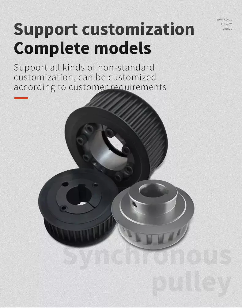
pulley

Common uses of a pulley

A pulley is a common mechanical device used to increase the force needed to lift a heavy object. Most commonly, these devices are used in construction equipment. These machines use high-10sion ropes to transfer heavy objects from 1 floor to another. Other common uses of a pulley include buckets and flagpoles. These devices are extremely useful in a wide range of applications. To learn more about the common uses of pulleys, keep reading.
A pulley is a wheel with grooves for holding rope. Its purpose is to change the direction and point at which a pulling force acts. It is usually used in sets to reduce the amount of force needed to lift a load, but the work involved is similar. Pulleys are also used in rock climbing devices. For many applications, a pulley is a vital part of construction.
The most common use of a pulley involves hoisting and lowering a flag. Other examples include clotheslines, bird feeders, and escalators. Pulleys are also commonly used on oil derricks. Many other common applications include hoisting and lowering garage doors. Pulley systems are also used in engines and cranes. For more information, check out our interactive pulley diagram!
Pulleys can also be used to lower total work required for a task. In many cases, a pulley will consist of 2 parts: the pulley hub and the shaft pulley. The hub clamps the shaft pulley, while the pulley itself is connected to the motor or other device. If you’re looking for a pulley, it’s important to learn how it works.
The most common uses for a pulley involve lifting heavy objects, and the mechanism used to lift them is known as a pulley. A pulley is an industrial device that uses 2 wheels to reduce the force needed to lift a weight. The pulley reduces this force by half by allowing the user to pull on the rope 4 times as far. The pulley also allows for a smaller lifting distance.

Main parts of a pulley

A pulley consists of the main element of a system. This is typically a cable, rope, belt, or chain. There are 2 basic types of pulleys – a Driver Pulley and a Follower Pulley. Pulleys are available in small and large sizes. The periphery part of the pulley is called the Face, and the protruding middle part is called the Crown. A pulley’s face can be round, rectangular, or even “V” shaped.
The first pulley was created by the Greek mathematician Archimedes in the third century BCE. These simple machines are made of a rope, an axle, and a wheel. The pulley’s end is attached to a person, object, or motor. These machines can be used in various tasks to lift heavy objects. The pulley is a great mechanical advantage for any lifter.
The ideal mechanical advantage of a pulley is defined by the number of rope segments that pull an object. The higher the number of loops on the rope, the higher the mechanical advantage. The greater the mechanical advantage, the less force is required to move the object. Likewise, the greater the distance the rope traverses, the higher the mechanical advantage of a pulley. There are several different types of pulley, depending on their combination of rope, wheel, and rope.
The basic components of a pulley are the face and hub, and the rope is threaded into the center of the pulley. The pulley is usually made of a rope and can be used to lift heavy weights. It can also be used to apply great force in any direction. Step pulleys have multiple faces, which are fixed in sequence. They can also increase the speed of the driven pulley.
A pulley is a simple machine consisting of a wheel, rope, or chain. These parts are crucial for making moving and lifting easier. Because they change the direction and magnitude of force, they can be a useful tool. Some pulleys even change direction. You can learn more about the pulley by downloading this resource today. The resources are designed to support the new 9-1 GCSEs in Design & Technology and Engineering.
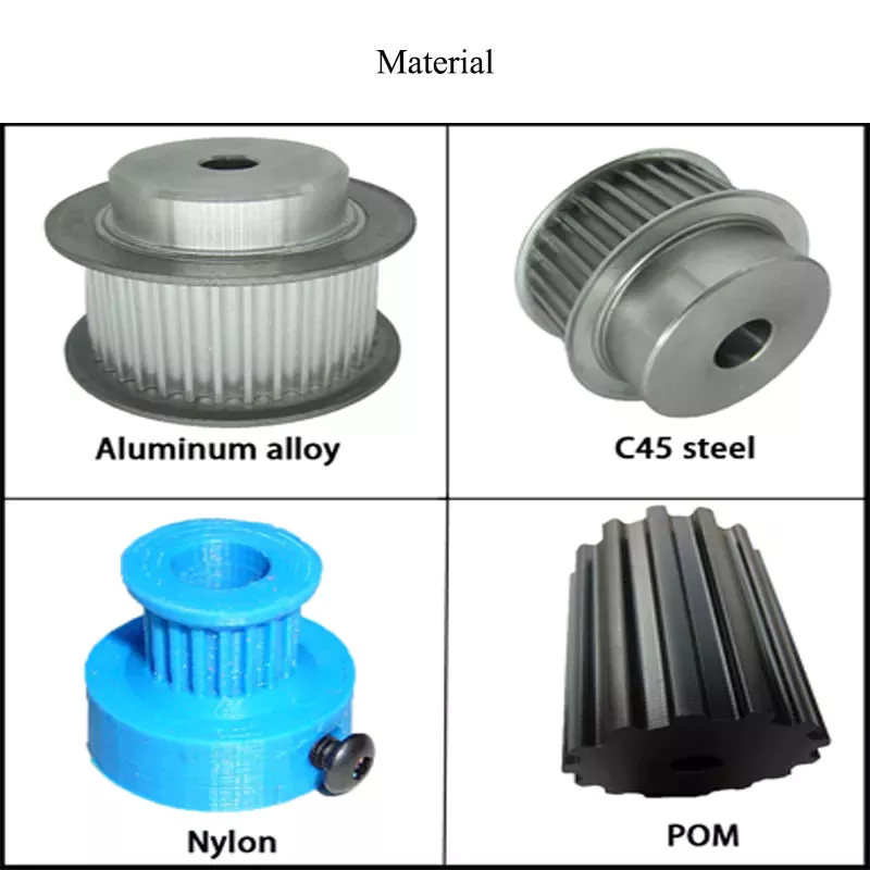
pulley

Mechanical advantage

Pulleys have been used to move heavy objects for centuries. When 2 rope sections are used, the weight of a 100kg mass can be moved with only 500 newtons of force. Adding an extra pulley increases the mechanical advantage. If the pulley has 2 wheels, the distance between the rope sections and the wheel grooves is only half the distance, but the mechanical advantage still applies. Adding another pulley increases the mechanical advantage, but can be risky.
Mechanical advantage is the ratio of force used versus force applied. The calculations are made under the assumption that the ropes and weights do not elongate or lose energy due to friction. If the weights are very light, the mechanical advantage is greater than that in the real world. To calculate the mechanical advantage, the weight of the load to be lifted must be the same as the weight of the person using the pulley.
A single moveable pulley has a mechanical advantage of two. The weight passes around the pulley, and 1 end of the rope is attached to a fixed point. The pulling force is then applied to the other end of the rope. The distance the weight travels doubles, or halved, depending on the direction of the pulley. Adding a second pulley reduces the distance and the effort required to lift it.
There are several ways to calculate the mechanical advantage of a pulley system. Some methods are specific to certain types of systems, while others work for all systems. The T-Method is a good choice in many applications, as it calculates the units of tension for each rope segment. Once you have determined the input force, you need to determine the maximum force that will be applied to each component. A compound pulley, for example, will require 4 units of tension for each rope segment.
In simple terms, the effort is the amount of force needed to lift the load. This force is measured in newtons (N). A mechanical advantage is often presented without units. If the student does not have this unit, you may need to convert the units to newtons, since 1 kilogram is equal to 10 newtons. If you can’t figure out the units of effort, you can use the KWL chart provided by the teacher.
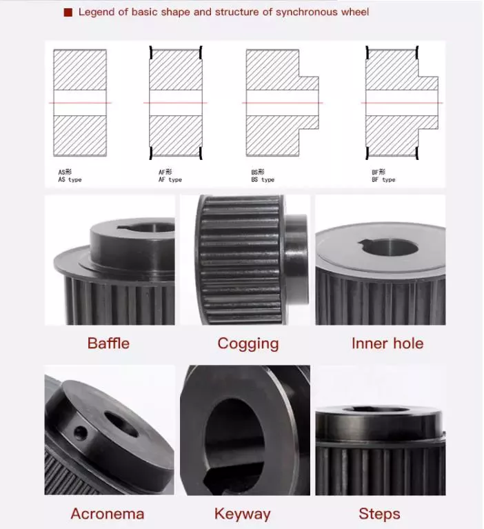
pulley

Safety precautions

There are a few safety precautions you should take when using a pulley. First, always check the SWL (safe working load) before attaching anything to the pulley. This indicates the maximum weight and angle the pulley can safely handle. Second, make sure that your work area is free from people and debris. Third, wear a hard hat to protect your head from blows and falling objects.
Another important consideration is anchoring. Although the pulley reduces the weight of an object, it is not enough to eliminate the weight. This is especially true if you are hoisting a heavy object, such as a motorcycle or lawnmower. It is important to ensure that the anchoring point can support the entire weight of the load. It is also important to follow proper anchoring procedures when using a pulley to lift a motorcycle or lawnmower.
In addition to the safety latch, you should use a tag line to control the suspended load. Remember that a chain pulley block is necessary for vertical lifting. You should also wear personal protective equipment (PPE) while using a pulley to avoid injuries. If your workplace does not have an PPE policy, you should consider implementing a similar policy. These safety guidelines are a good start.
If you are using a pulley to lift heavy objects, make sure to wear gloves. Those who are not familiar with rope-pulling will have an easier time demonstrating how it works. If you are using a rope-pulley system in a classroom, be sure to follow lab safety guidelines. Wear cloth gloves, clear the area, and do not jerk the rope. In addition, never allow yourself to be pulled into the rope by an unfamiliar person.
Another important safety precaution when using a pulley is to ensure that the anchor point for your system is adequate to support the weight of the object being lifted. Check with the manufacturer of the pulley to find out what its weight limit is, as some types of pulleys are designed to lift much heavier weights than others. It is important to follow all manufacturer’s instructions when using a pulley.

China Standard Custom CNC Milling Machine Lathe Spare Auto Motor Motorcycle Turning Engine Metal Brass Copper Steel Aluminum Part     near me manufacturer China Standard Custom CNC Milling Machine Lathe Spare Auto Motor Motorcycle Turning Engine Metal Brass Copper Steel Aluminum Part     near me manufacturer

China factory Custom Precision CNC Machining Hardware Metal Aluminum Part for Auto Motor Motorcycle Turning Engine wholesaler

Product Description

Basic Info
 

Surface treatment  polishing, chrome plating, zinc plating, nickel plating, clear/black anodizing, Black, Nitrogenation, sandblasting,  powder coating, etc.
Heat Treatment Nitride, Hardening etc.
Machining Equipment CNC Machining Center, CNC Turning Machine, CNC Milling Machine, Surface Grinders, Wire Cutting Machine,Electrical Discharge Machine,Drilling Machine, Rolling Machine
 
 
 Quality We have kind of measuring equipment like Coordinate Measuring Machine to check the pecision for the parts, and we will also make full protect for package for shipping. High Precision quality as drawing request will be provided.
 
Application Heavy industrial machinery, automation equipment, vehicles, package machines, food processing machines, agricultural machines, electronic machines, etc
Lead Time According to the quantity and drawings’ difficulties of clients
Trade Terms EXW, FOB, CIF, DAP.etc
Drawing Format . pdf / .dwg / .igs / .stp etc.

FAQ

Q1: Are you a trading company or a manufacturer? Location?
A1: We are a factory located in Bao’an, HangZhou, China.

Q2: Is there any MOQ required?
A2: No, there is no MOQ required, even 1 piece we can also process. 

Q3: How to ensure the quality of every process?
A3: The part will be checked when each process is finished, which makes sure there are no defects on the customers’ end.

Q4: How can I get the quotation?
A4: We will offer you the quotation within 12 working hours after receiving your detailed information. In order to quote you faster and more accurate, please provide us with the following information together with your inquiry:
1) CAD or 3D Drawings
2) Tolerance.
3) Material requirement
4) Surface treatment
5) Quantity (per order/per month/annual)
6) Any special demands or requirements, such as packing, labels, delivery, etc.

Q5: How do you make sure my drawings are confidential?
A5: we will keep them well and not release them to others without your permission. NDA can be also signed, if you needed.

Q6: Why choose HangZhou XYX Precision Co., Ltd?
A6:  1. Years of experience, which can offer you tailored solutions to your projects.
        2. Flexibility in lead time.
        3. Assurance in high-quality parts.


How to Choose the Right Worm Shaft

You might be curious to know how to choose the right Worm Shaft. In this article, you will learn about worm modules with the same pitch diameter, Double-thread worm gears, and Self-locking worm drive. Once you have chosen the proper Worm Shaft, you will find it easier to use the equipment in your home. There are many advantages to selecting the right Worm Shaft. Read on to learn more.
worm shaft

Concave shape

The concave shape of a worm’s shaft is an important characteristic for the design of a worm gearing. Worm gearings can be found in a wide range of shapes, and the basic profile parameters are available in professional and firm literature. These parameters are used in geometry calculations, and a selection of the right worm gearing for a particular application can be based on these requirements.
The thread profile of a worm is defined by the tangent to the axis of its main cylinder. The teeth are shaped in a straight line with a slightly concave shape along the sides. It resembles a helical gear, and the profile of the worm itself is straight. This type of gearing is often used when the number of teeth is greater than a certain limit.
The geometry of a worm gear depends on the type and manufacturer. In the earliest days, worms were made similar to simple screw threads, and could be chased on a lathe. During this time, the worm was often made with straight-sided tools to produce threads in the acme plane. Later, grinding techniques improved the thread finish and reduced distortions resulting from hardening.
When a worm gearing has multiple teeth, the pitch angle is a key parameter. A greater pitch angle increases efficiency. If you want to increase the pitch angle without increasing the number of teeth, you can replace a worm pair with a different number of thread starts. The helix angle must increase while the center distance remains constant. A higher pitch angle, however, is almost never used for power transmissions.
The minimum number of gear teeth depends on the angle of pressure at zero gearing correction. The diameter of the worm is d1, and is based on a known module value, mx or mn. Generally, larger values of m are assigned to larger modules. And a smaller number of teeth is called a low pitch angle. In case of a low pitch angle, spiral gearing is used. The pitch angle of the worm gear is smaller than 10 degrees.
worm shaft

Multiple-thread worms

Multi-thread worms can be divided into sets of one, two, or 4 threads. The ratio is determined by the number of threads on each set and the number of teeth on the apparatus. The most common worm thread counts are 1,2,4, and 6. To find out how many threads you have, count the start and end of each thread and divide by two. Using this method, you will get the correct thread count every time.
The tangent plane of a worm’s pitch profile changes as the worm moves lengthwise along the thread. The lead angle is greatest at the throat, and decreases on both sides. The curvature radius r” varies proportionally with the worm’s radius, or pitch angle at the considered point. Hence, the worm leads angle, r, is increased with decreased inclination and decreases with increasing inclination.
Multi-thread worms are characterized by a constant leverage between the gear surface and the worm threads. The ratio of worm-tooth surfaces to the worm’s length varies, which enables the wormgear to be adjusted in the same direction. To optimize the gear contact between the worm and gear, the tangent relationship between the 2 surfaces is optimal.
The efficiency of worm gear drives is largely dependent on the helix angle of the worm. Multiple thread worms can improve the efficiency of the worm gear drive by as much as 25 to 50% compared to single-thread worms. Worm gears are made of bronze, which reduces friction and heat on the worm’s teeth. A specialized machine can cut the worm gears for maximum efficiency.

Double-thread worm gears

In many different applications, worm gears are used to drive a worm wheel. These gears are unique in that the worm cannot be reversed by the power applied to the worm wheel. Because of their self-locking properties, they can be used to prevent reversing motion, although this is not a dependable function. Applications for worm gears include hoisting equipment, elevators, chain blocks, fishing reels, and automotive power steering. Because of their compact size, these gears are often used in applications with limited space.
Worm sets typically exhibit more wear than other types of gears, and this means that they require more limited contact patterns in new parts. Worm wheel teeth are concave, making it difficult to measure tooth thickness with pins, balls, and gear tooth calipers. To measure tooth thickness, however, you can measure backlash, a measurement of the spacing between teeth in a gear. Backlash can vary from 1 worm gear to another, so it is important to check the backlash at several points. If the backlash is different in 2 places, this indicates that the teeth may have different spacing.
Single-thread worm gears provide high speed reduction but lower efficiency. A multi-thread worm gear can provide high efficiency and high speed, but this comes with a trade-off in terms of horsepower. However, there are many other applications for worm gears. In addition to heavy-duty applications, they are often used in light-duty gearboxes for a variety of functions. When used in conjunction with double-thread worms, they allow for a substantial speed reduction in 1 step.
Stainless-steel worm gears can be used in damp environments. The worm gear is not susceptible to rust and is ideal for wet and damp environments. The worm wheel’s smooth surfaces make cleaning them easy. However, they do require lubricants. The most common lubricant for worm gears is mineral oil. This lubricant is designed to protect the worm drive.
worm shaft

Self-locking worm drive

A self-locking worm drive prevents the platform from moving backward when the motor stops. A dynamic self-locking worm drive is also possible but does not include a holding brake. This type of self-locking worm drive is not susceptible to vibrations, but may rattle if released. In addition, it may require an additional brake to keep the platform from moving. A positive brake may be necessary for safety.
A self-locking worm drive does not allow for the interchangeability of the driven and driving gears. This is unlike spur gear trains that allow both to interchange positions. In a self-locking worm drive, the driving gear is always engaged and the driven gear remains stationary. The drive mechanism locks automatically when the worm is operated in the wrong manner. Several sources of information on self-locking worm gears include the Machinery’s Handbook.
A self-locking worm drive is not difficult to build and has a great mechanical advantage. In fact, the output of a self-locking worm drive cannot be backdriven by the input shaft. DIYers can build a self-locking worm drive by modifying threaded rods and off-the-shelf gears. However, it is easier to make a ratchet and pawl mechanism, and is significantly less expensive. However, it is important to understand that you can only drive 1 worm at a time.
Another advantage of a self-locking worm drive is the fact that it is not possible to interchange the input and output shafts. This is a major benefit of using such a mechanism, as you can achieve high gear reduction without increasing the size of the gear box. If you’re thinking about buying a self-locking worm gear for a specific application, consider the following tips to make the right choice.
An enveloping worm gear set is best for applications requiring high accuracy and efficiency, and minimum backlash. Its teeth are shaped differently, and the worm’s threads are modified to increase surface contact. They are more expensive to manufacture than their single-start counterparts, but this type is best for applications where accuracy is crucial. The worm drive is also a great option for heavy trucks because of their large size and high-torque capacity.

China factory Custom Precision CNC Machining Hardware Metal Aluminum Part for Auto Motor Motorcycle Turning Engine     wholesaler China factory Custom Precision CNC Machining Hardware Metal Aluminum Part for Auto Motor Motorcycle Turning Engine     wholesaler