Tag Archives: machinery for

China Good quality Agricultural Machinery Parts for John Deere Tractor Clutch Disc with Hot selling

Product Description

FRICTION MATERIAL
Made of special friction material with the original standard, can withstand the harsh environment and ensure the service life

Friction materials from well-known manufacturers

Ceramic copper base & imported material is selected as friction material

Technical Update
Before improvement, there are 8 damping springs with firm structure, small torsion angle, and large stiffness

After improvement, there are 6 damping springs with firm structure, large torsion angle, and small stiffness

Why choose us

* The company was founded in 1998
* The plant covers an area of 7 509 2788       3 RE177574 887889M94
3599462M91 3757103M92 515 4514      514 4741      515 6514 3757111M91
3757111M91
3757115R92 AL 39244
AL 57415
AL 61754
AL 68571 82011592


Packaging Picture

Certificates


FAQ

Q1: Where is the location of OUTAISHI Automotive Parts CO LTD?
A1: Our company locals in HangZhou city, around 800kms from HangZhou, 700kms from ZheJiang , and it is very convenient to travel.
       Only 1.5 hours by air or 4 hours by train from HangZhou or ZheJiang .

Q2: What are the main products of OUTAISHI Automotive Parts CO LTD?
A2: Our main products are clutch assembly, clutch cover, clutch disc, clutch bearing for Automobiles, construction machinery, and tractor.

Q3: What are your terms of packing?
A3: Generally, we pack your goods using brown or white blank neutral boxes. If you have a legally registered patent, we can pack the goods in your branded boxes after getting your authorization letters.

Q4: What are your terms of payment?
A4: T/T 30% as deposit, and 70% before delivery. We’ll show you the photos of the products and packages before you pay the balance.

Q5: How long I can get the goods after confirming the order?
A5: We need 10-50days for production; If you could arrange 100%TT, we will book ship advanced, you don’t need to waste time waiting for delivery.

Q6: Can you produce according to the samples?
A6: Yes, we can produce your samples or technical drawings. We can build the molds and fixtures.

Q7: What is your guarantee?
A7: 1 year or 12000km;

Q8: What should I do if claims appear?
A8: When the claims appear, what we need are the pictures of products, the use condition brief, and the order information. CHALLENWAY will analyze the problem, even field investigation, and work out a final option with customers.

Q9. Do you test all your goods before delivery?
A9: Yes, we have 100% test before delivery

Q10: How do you make our business a long-term and good relationship?
A10:1.We keep good quality and competitive price to ensure our customers benefit ;
        2. We respect every customer as our friend and we sincerely do business and make friends with them, no matter where they come from.


How to tell if your driveshaft needs replacing

What is the cause of the unbalanced drive shaft? Unstable U-joint? Your car may make clicking noises while driving. If you can hear it from both sides, it might be time to hand it over to the mechanic. If you’re not sure, read on to learn more. Fortunately, there are many ways to tell if your driveshaft needs replacing.

unbalanced

An unbalanced driveshaft can be the source of strange noises and vibrations in your vehicle. To fix this problem, you should contact a professional. You can try a number of things to fix it, including welding and adjusting the weight. The following are the most common methods. In addition to the methods above, you can use standardized weights to balance the driveshaft. These standardized weights are attached to the shaft by welders.
An unbalanced drive shaft typically produces lateral vibrations per revolution. This type of vibration is usually caused by a damaged shaft, missing counterweights, or a foreign object stuck on the drive shaft. On the other hand, torsional vibrations occur twice per revolution, and they are caused by shaft phase shifts. Finally, critical speed vibration occurs when the RPM of the drive shaft exceeds its rated capacity. If you suspect a driveshaft problem, check the following:
Manually adjusting the imbalance of a drive shaft is not the easiest task. To avoid the difficulty of manual balancing, you can choose to use standardized weights. These weights are fixed on the outer circumference of the drive shaft. The operator can manually position the weight on the shaft with special tools, or use a robot. However, manual balancers have many disadvantages.
air-compressor

unstable

When the angular velocity of the output shaft is not constant, it is unstable. The angular velocity of the output shaft is 0.004 at ph = 29.5 and 1.9 at t = 1.9. The angular velocity of the intermediate shaft is not a problem. But when it’s unstable, the torque applied to it is too much for the machine. It might be a good idea to check the tension on the shaft.
An unstable drive shaft can cause a lot of noise and mechanical vibration. It can lead to premature shaft fatigue failure. CZPT studies the effect of shaft vibration on the rotor bearing system. They investigated the effect of flex coupling misalignment on the vibration of the rotor bearing system. They assume that the vibrational response has 2 components: x and y. However, this approach has limited application in many situations.
Experimental results show that the presence of cracks in the output shaft may mask the unbalanced excitation characteristics. For example, the presence of superharmonic peaks on the spectrum is characteristic of cracks. The presence of cracks in the output shaft masks unbalanced excitation characteristics that cannot be detected in the transient response of the input shaft. Figure 8 shows that the frequency of the rotor increases at critical speed and decreases as the shaft passes the natural frequency.

Unreliable

If you’re having trouble driving your car, chances are you’ve run into an unreliable driveshaft. This type of drivetrain can cause the wheels to stick or not turn at all, and also limit the overall control of the car. Whatever the reason, these issues should be resolved as soon as possible. Here are some symptoms to look for when diagnosing a driveshaft fault. Let’s take a closer look.
The first symptom you may notice is an unreliable drive shaft. You may feel vibrations, or hear noises under the vehicle. Depending on the cause, it could be a broken joint or a broken shaft. The good news is that driveshaft repairs are generally relatively inexpensive and take less time than a complete drivetrain replacement. If you’re not sure what to do, CZPT has a guide to replacing the U-connector.
One of the most common signs of an unreliable driveshaft is clanging and vibration. These sounds can be caused by worn bushings, loose U-joints, or damaged center bearings. This can cause severe vibration and noise. You can also feel these vibrations through the steering wheel or the floor. An unreliable driveshaft is a symptom of a bigger problem.
air-compressor

Unreliable U-joints

A car with an unreliable U-joint on the drive shaft can be dangerous. A bad u-joint can prevent the vehicle from driving properly and may even cause you trouble. Unreliable u-joints are cheap to replace and you should try getting parts from quality manufacturers. Unreliable U-joints can cause the car to vibrate in the chassis or gear lever. This is a sure sign that your car has been neglected in maintenance.
Replacing a U-joint is not a complicated task, but it requires special tools and a lot of elbow grease. If you don’t have the right tools, or you’re unfamiliar with mechanical terminology, it’s best to seek the help of a mechanic. A professional mechanic will be able to accurately assess the problem and propose an appropriate solution. But if you don’t feel confident enough, you can replace your own U-connector by following a few simple steps.
To ensure the vehicle’s driveshaft is not damaged, check the U-joint for wear and lubrication. If the U-joint is worn, the metal parts are likely to rub against each other, causing wear. The sooner a problem is diagnosed, the faster it can be resolved. Also, the longer you wait, the more you lose on repairs.

damaged drive shaft

The driveshaft is the part of the vehicle that connects the wheels. If the driveshaft is damaged, the wheels may stop turning and the vehicle may slow down or stop moving completely. It bears the weight of the car itself as well as the load on the road. So even a slight bend or break in the drive shaft can have dire consequences. Even a piece of loose metal can become a lethal missile if dropped from a vehicle.
If you hear a screeching noise or growl from your vehicle when shifting gears, your driveshaft may be damaged. When this happens, damage to the u-joint and excessive slack in the drive shaft can result. These conditions can further damage the drivetrain, including the front half. You should replace the driveshaft as soon as you notice any symptoms. After replacing the driveshaft, you can start looking for signs of wear.
A knocking sound is a sign of damage to the drive shaft. If you hear this sound while driving, it may be due to worn couplings, damaged propshaft bearings, or damaged U-joints. In some cases, the knocking noise can even be caused by a damaged U-joint. When this happens, you may need to replace the entire driveshaft, requiring a new one.
air-compressor

Maintenance fees

The cost of repairing a driveshaft varies widely, depending on the type and cause of the problem. A new driveshaft costs between $300 and $1,300, including labor. Repairing a damaged driveshaft can cost anywhere from $200 to $300, depending on the time required and the type of parts required. Symptoms of a damaged driveshaft include unresponsiveness, vibration, chassis noise and a stationary car.
The first thing to consider when estimating the cost of repairing a driveshaft is the type of vehicle you have. Some vehicles have more than one, and the parts used to make them may not be compatible with other cars. Even if the same car has 2 driveshafts, the damaged ones will cost more. Fortunately, many auto repair shops offer free quotes to repair damaged driveshafts, but be aware that such work can be complicated and expensive.

China Good quality Agricultural Machinery Parts for John Deere Tractor Clutch Disc     with Hot sellingChina Good quality Agricultural Machinery Parts for John Deere Tractor Clutch Disc     with Hot selling

China Hot selling OEM Custom Lost Wax Cast Steel Sand Castings Iron Diecast Aluminum Casting Parts with CNC Machining for Agricultural Machinery Baler Piston Roller with Hot selling

Product Description

 Product description 
 

Specification Precision casting,Lost wax casting, Investment casting
Material Stainless steel,Steel,Brass,Copper,Aluminum,Iron
Machining CNC machining center, CNC lathe
Casting tolerance IT5 – IT7,CT5-7
Machining tolerance +/- 0.005mm,ISO2768-f,ISO-mk
Heat treatment Solid solution annealed,quench and tempering
Weight range 0.1Kg-120Kg
Dimensions  ≤1200mm×800mm×400mm
Surface finishment Ra1.6-Ra3.2
Finish Polishing,Shoot blasting,Glass bead sand blasting,etc.

The Investment Casting Process:


Precision casting products:


Our advantage:

* One-Sotp service(from design to mass production)

* OEM /ODM Customized services

* Rapid prototyping & low-volume production

* High quality & low prices

* Highly skilled manufacturing process.

* Strict quality Control System.

Our promise:

* The delivery time and the package can be controled according to the customers’ requirement completely.

* we will produce the products seriously according to the drawings, and make sure all the products is suitable for the custoners.

* We will communicate with the customers all the time about the products, we will send the pictures to the customers, so that they can know the Processing process

Our Policy:

Innovation and developing in Technique

High level of expertise

Outstanding quality

On-time delivery to customer needs

SERVICE:
 

Types of Splines

There are 4 types of splines: Involute, Parallel key, helical, and ball. Learn about their characteristics. And, if you’re not sure what they are, you can always request a quotation. These splines are commonly used for building special machinery, repair jobs, and other applications. The CZPT Manufacturing Company manufactures these shafts. It is a specialty manufacturer and we welcome your business.
splineshaft

Involute splines

The involute spline provides a more rigid and durable structure, and is available in a variety of diameters and spline counts. Generally, steel, carbon steel, or titanium are used as raw materials. Other materials, such as carbon fiber, may be suitable. However, titanium can be difficult to produce, so some manufacturers make splines using other constituents.
When splines are used in shafts, they prevent parts from separating during operation. These features make them an ideal choice for securing mechanical assemblies. Splines with inward-curving grooves do not have sharp corners and are therefore less likely to break or separate while they are in operation. These properties help them to withstand high-speed operations, such as braking, accelerating, and reversing.
A male spline is fitted with an externally-oriented face, and a female spline is inserted through the center. The teeth of the male spline typically have chamfered tips to provide clearance with the transition area. The radii and width of the teeth of a male spline are typically larger than those of a female spline. These specifications are specified in ANSI or DIN design manuals.
The effective tooth thickness of a spline depends on the involute profile error and the lead error. Also, the spacing of the spline teeth and keyways can affect the effective tooth thickness. Involute splines in a splined shaft are designed so that at least 25 percent of the spline teeth engage during coupling, which results in a uniform distribution of load and wear on the spline.

Parallel key splines

A parallel splined shaft has a helix of equal-sized grooves around its circumference. These grooves are generally parallel or involute. Splines minimize stress concentrations in stationary joints and allow linear and rotary motion. Splines may be cut or cold-rolled. Cold-rolled splines have more strength than cut spines and are often used in applications that require high strength, accuracy, and a smooth surface.
A parallel key splined shaft features grooves and keys that are parallel to the axis of the shaft. This design is best suited for applications where load bearing is a primary concern and a smooth motion is needed. A parallel key splined shaft can be made from alloy steels, which are iron-based alloys that may also contain chromium, nickel, molybdenum, copper, or other alloying materials.
A splined shaft can be used to transmit torque and provide anti-rotation when operating as a linear guide. These shafts have square profiles that match up with grooves in a mating piece and transmit torque and rotation. They can also be easily changed in length, and are commonly used in aerospace. Its reliability and fatigue life make it an excellent choice for many applications.
The main difference between a parallel key splined shaft and a keyed shaft is that the former offers more flexibility. They lack slots, which reduce torque-transmitting capacity. Splines offer equal load distribution along the gear teeth, which translates into a longer fatigue life for the shaft. In agricultural applications, shaft life is essential. Agricultural equipment, for example, requires the ability to function at high speeds for extended periods of time.
splineshaft

Involute helical splines

Involute splines are a common design for splined shafts. They are the most commonly used type of splined shaft and feature equal spacing among their teeth. The teeth of this design are also shorter than those of the parallel spline shaft, reducing stress concentration. These splines can be used to transmit power to floating or permanently fixed gears, and reduce stress concentrations in the stationary joint. Involute splines are the most common type of splined shaft, and are widely used for a variety of applications in automotive, machine tools, and more.
Involute helical spline shafts are ideal for applications involving axial motion and rotation. They allow for face coupling engagement and disengagement. This design also allows for a larger diameter than a parallel spline shaft. The result is a highly efficient gearbox. Besides being durable, splines can also be used for other applications involving torque and energy transfer.
A new statistical model can be used to determine the number of teeth that engage for a given load. These splines are characterized by a tight fit at the major diameters, thereby transferring concentricity from the shaft to the female spline. A male spline has chamfered tips for clearance with the transition area. ANSI and DIN design manuals specify the different classes of fit.
The design of involute helical splines is similar to that of gears, and their ridges or teeth are matched with the corresponding grooves in a mating piece. It enables torque and rotation to be transferred to a mate piece while maintaining alignment of the 2 components. Different types of splines are used in different applications. Different splines can have different levels of tooth height.

Involute ball splines

When splines are used, they allow the shaft and hub to engage evenly over the shaft’s entire circumference. Because the teeth are evenly spaced, the load that they can transfer is uniform and their position is always the same regardless of shaft length. Whether the shaft is used to transmit torque or to transmit power, splines are a great choice. They provide maximum strength and allow for linear or rotary motion.
There are 3 basic types of splines: helical, crown, and ball. Crown splines feature equally spaced grooves. Crown splines feature involute sides and parallel sides. Helical splines use involute teeth and are often used in small diameter shafts. Ball splines contain a ball bearing inside the splined shaft to facilitate rotary motion and minimize stress concentration in stationary joints.
The 2 types of splines are classified under the ANSI classes of fit. Fillet root splines have teeth that mesh along the longitudinal axis of rotation. Flat root splines have similar teeth, but are intended to optimize strength for short-term use. Both types of splines are important for ensuring the shaft aligns properly and is not misaligned.
The friction coefficient of the hub is a complex process. When the hub is off-center, the center moves in predictable but irregular motion. Moreover, when the shaft is centered, the center may oscillate between being centered and being off-center. To compensate for this, the torque must be adequate to keep the shaft in its axis during all rotation angles. While straight-sided splines provide similar centering, they have lower misalignment load factors.
splineshaft

Keyed shafts

Essentially, splined shafts have teeth or ridges that fit together to transfer torque. Because splines are not as tall as involute gears, they offer uniform torque transfer. Additionally, they provide the opportunity for torque and rotational changes and improve wear resistance. In addition to their durability, splined shafts are popular in the aerospace industry and provide increased reliability and fatigue life.
Keyed shafts are available in different materials, lengths, and diameters. When used in high-power drive applications, they offer higher torque and rotational speeds. The higher torque they produce helps them deliver power to the gearbox. However, they are not as durable as splined shafts, which is why the latter is usually preferred in these applications. And while they’re more expensive, they’re equally effective when it comes to torque delivery.
Parallel keyed shafts have separate profiles and ridges and are used in applications requiring accuracy and precision. Keyed shafts with rolled splines are 35% stronger than cut splines and are used where precision is essential. These splines also have a smooth finish, which can make them a good choice for precision applications. They also work well with gears and other mechanical systems that require accurate torque transfer.
Carbon steel is another material used for splined shafts. Carbon steel is known for its malleability, and its shallow carbon content helps create reliable motion. However, if you’re looking for something more durable, consider ferrous steel. This type contains metals such as nickel, chromium, and molybdenum. And it’s important to remember that carbon steel is not the only material to consider.

China Hot selling OEM Custom Lost Wax Cast Steel Sand Castings Iron Diecast Aluminum Casting Parts with CNC Machining for Agricultural Machinery Baler Piston Roller     with Hot sellingChina Hot selling OEM Custom Lost Wax Cast Steel Sand Castings Iron Diecast Aluminum Casting Parts with CNC Machining for Agricultural Machinery Baler Piston Roller     with Hot selling

China high quality Truck Parts for CZPT Cart, Trailer, Livestock, Combine, Agricultural Machinery with high quality

Product Description

Truck Parts For Tractor,; Combine,; Trailer,; Cultivator,; Plough,; CZPT Car Parts
Rear View Camera For Vehicle(DF-8053);

Waterproof IR Side Camera(MODEL:;DF-8053);
Image Type:; 1/3″ Color CCD
Horizontal Resolution:;600TV Lines
Effective pixel:;NTSC:;976(H);×494(V); PAL:;976(H);x582(V);
Usable Illumination :; 0Lux ( Built in 10pcs IR  for Picture Support in the Dark);
Free viewing angle:; 130°
Waterproof:; 100% Waterproof IP69K Rating
Shockproof:; 10G
Video Output:;1.;0Vp-p75Ω
Operation Temperature:; -20°C~+70°C
Power supply:;DC12V
Dimensions:; 55(L); x 63(W); x 74(H);mm
 

Product Accessories
U- Support Bracket,;Angle Adjustment Screw,;Removable Sun Visor,;Electrical Connecting Cable,;15m cable*4,; Auto cigarette lighter,;User’s Manual

About camera:;
1.;Our camera ‘s waterproof level is IP69K,;we don’t like other company just put the product into the water pool to have the waterproof test,; we have the professional test equipment especially for camera to guarantee the waterproof level is 100%.;This is the most difference between our product and others.;
 
2.; Every camera before take out the factory we will do the vacuum test,;we pumped out the air and put some nitrogen into it,;to make sure the vacuum dry environment.;
 
3.;Our camera is used truely original sony 720tv lines,;to make sure our camera is full HD resolution.;
 
4.;Our IC card is the industrial level which is different from the consumer level.;

Benefits and Uses of Miter Gears

If you’ve ever looked into the differences between miter gears, you’re probably wondering how to choose between a Straight toothed and Hypoid one. Before you decide, however, make sure you know about backlash and what it means. Backlash is the difference between the addendum and dedendum, and it prevents jamming of the gears, protects the mating gear surfaces, and allows for thermal expansion during operation.
gear

Spiral bevel gears

Spiral bevel gears are designed to increase efficiency and reduce cost. The spiral shape creates a profile in which the teeth are cut with a slight curve along their length, making them an excellent choice for heavy-duty applications. Spiral bevel gears are also hypoid gears, with no offsets. Their smaller size means that they are more compact than other types of right-angle gears, and they are much quieter than other types of gear.
Spiral bevel gears feature helical teeth arranged in a 90-degree angle. The design features a slight curve to the teeth, which reduces backlash while increasing flexibility. Because they have no offsets, they won’t slip during operation. Spiral bevel gears also have less backlash, making them an excellent choice for high-speed applications. They are also carefully spaced to distribute lubricant over a larger area. They are also very accurate and have a locknut design that prevents them from moving out of alignment.
In addition to the geometric design of bevel gears, CZPT can produce 3D models of spiral bevel gears. This software has gained widespread attention from many companies around the world. In fact, CZPT, a major manufacturer of 5-axis milling machines, recently machined a prototype using a spiral bevel gear model. These results prove that spiral bevel gears can be used in a variety of applications, ranging from precision machining to industrial automation.
Spiral bevel gears are also commonly known as hypoid gears. Hypoid gears differ from spiral bevel gears in that their pitch surface is not at the center of the meshing gear. The benefit of this gear design is that it can handle large loads while maintaining its unique features. They also produce less heat than their bevel counterparts, which can affect the efficiency of nearby components.

Straight toothed miter gears

Miter gears are bevel gears that have a pitch angle of 90 degrees. Their gear ratio is 1:1. Miter gears come in straight and spiral tooth varieties and are available in both commercial and high precision grades. They are a versatile tool for any mechanical application. Below are some benefits and uses of miter gears. A simple explanation of the basic principle of this gear type is given. Read on for more details.
When selecting a miter gear, it is important to choose the right material. Hard faced, high carbon steel is appropriate for applications requiring high load, while nylon and injection molding resins are suitable for lower loads. If a particular gear becomes damaged, it’s advisable to replace the entire set, as they are closely linked in shape. The same goes for spiral-cut miter gears. These geared products should be replaced together for proper operation.
Straight bevel gears are the easiest to manufacture. The earliest method was using an indexing head on a planer. Modern manufacturing methods, such as the Revacycle and Coniflex systems, made the process more efficient. CZPT utilizes these newer manufacturing methods and patented them. However, the traditional straight bevel is still the most common and widely used type. It is the simplest to manufacture and is the cheapest type.
SDP/Si is a popular supplier of high-precision gears. The company produces custom miter gears, as well as standard bevel gears. They also offer black oxide and ground bore and tooth surfaces. These gears can be used for many industrial and mechanical applications. They are available in moderate quantities from stock and in partial sizes upon request. There are also different sizes available for specialized applications.
gear

Hypoid bevel gears

The advantages of using Hypoid bevel and helical gears are obvious. Their high speed, low noise, and long life make them ideal for use in motor vehicles. This type of gear is also becoming increasingly popular in the power transmission and motion control industries. Compared to standard bevel and helical gears, they have a higher capacity for torque and can handle high loads with less noise.
Geometrical dimensioning of bevel/hypoid bevel gears is essential to meet ANSI/AGMA/ISO standards. This article examines a few ways to dimension hypoid bevel and helical gears. First, it discusses the limitations of the common datum surface when dimensioning bevel/helical gear pairs. A straight line can’t be parallel to the flanks of both the gear and the pinion, which is necessary to determine “normal backlash.”
Second, hypoid and helical gears have the same angular pitch, which makes the manufacturing process easier. Hypoid bevel gears are usually made of 2 gears with equal angular pitches. Then, they are assembled to match 1 another. This reduces noise and vibration, and increases power density. It is recommended to follow the standard and avoid using gears that have mismatched angular pitches.
Third, hypoid and helical gears differ in the shape of the teeth. They are different from standard gears because the teeth are more elongated. They are similar in appearance to spiral bevel gears and worm gears, but differ in geometry. While helical gears are symmetrical, hypoid bevel gears are non-conical. As a result, they can produce higher gear ratios and torque.

Crown bevel gears

The geometrical design of bevel gears is extremely complex. The relative contact position and flank form deviations affect both the paired gear geometry and the tooth bearing. In addition, paired gears are also subject to process-linked deviations that affect the tooth bearing and backlash. These characteristics require the use of narrow tolerance fields to avoid quality issues and production costs. The relative position of a miter gear depends on the operating parameters, such as the load and speed.
When selecting a crown bevel gear for a miter-gear system, it is important to choose 1 with the right tooth shape. The teeth of a crown-bevel gear can differ greatly in shape. The radial pitch and diametral pitch cone angles are the most common. The tooth cone angle, or “zerol” angle, is the other important parameter. Crown bevel gears have a wide range of tooth pitches, from flat to spiral.
Crown bevel gears for miter gear are made of high-quality materials. In addition to metal, they can be made of plastic or pre-hardened alloys. The latter are preferred as the material is less expensive and more flexible than steel. Furthermore, crown bevel gears for miter gears are extremely durable, and can withstand extreme conditions. They are often used to replace existing gears that are damaged or worn.
When selecting a crown bevel gear for a miter gear, it is important to know how they relate to each other. This is because the crown bevel gears have a 1:1 speed ratio with a pinion. The same is true for miter gears. When comparing crown bevel gears for miter gears, be sure to understand the radii of the pinion and the ring on the pinion.
gear

Shaft angle requirements for miter gears

Miter gears are used to transmit motion between intersecting shafts at a right angle. Their tooth profile is shaped like the mitre hat worn by a Catholic bishop. Their pitch and number of teeth are also identical. Shaft angle requirements vary depending on the type of application. If the application is for power transmission, miter gears are often used in a differential arrangement. If you’re installing miter gears for power transmission, you should know the mounting angle requirements.
Shaft angle requirements for miter gears vary by design. The most common arrangement is perpendicular, but the axes can be angled to almost any angle. Miter gears are also known for their high precision and high strength. Their helix angles are less than 10 degrees. Because the shaft angle requirements for miter gears vary, you should know which type of shaft angle you require before ordering.
To determine the right pitch cone angle, first determine the shaft of the gear you’re designing. This angle is called the pitch cone angle. The angle should be at least 90 degrees for the gear and the pinion. The shaft bearings must also be capable of bearing significant forces. Miter gears must be supported by bearings that can withstand significant forces. Shaft angle requirements for miter gears vary from application to application.
For industrial use, miter gears are usually made of plain carbon steel or alloy steel. Some materials are more durable than others and can withstand higher speeds. For commercial use, noise limitations may be important. The gears may be exposed to harsh environments or heavy machine loads. Some types of gears function with teeth missing. But be sure to know the shaft angle requirements for miter gears before you order one.

China high quality Truck Parts for CZPT Cart, Trailer, Livestock, Combine, Agricultural Machinery     with high qualityChina high quality Truck Parts for CZPT Cart, Trailer, Livestock, Combine, Agricultural Machinery     with high quality

China factory CNC Processing Machinery Metal Stainless Steel Copper Brass Part for Engine Motorcycle near me manufacturer

Product Description

Basic Info
 

Surface treatment  polishing, chrome plating, zinc plating, nickel plating, clear/black anodizing, Black, Nitrogenation, sandblasting,  powder coating, etc.
Heat Treatment Nitride, Hardening etc.
Machining Equipment CNC Machining Center, CNC Turning Machine, CNC Milling Machine, Surface Grinders, Wire Cutting Machine,Electrical Discharge Machine,Drilling Machine, Rolling Machine
 
 
 Quality We have kind of measuring equipment like Coordinate Measuring Machine to check the pecision for the parts, and we will also make full protect for package for shipping. High Precision quality as drawing request will be provided.
 
Application Heavy industrial machinery, automation equipment, vehicles, package machines, food processing machines, agricultural machines, electronic machines, etc
Lead Time According to the quantity and drawings’ difficulties of clients
Trade Terms EXW, FOB, CIF, DAP.etc
Drawing Format . pdf / .dwg / .igs / .stp etc.

FAQ

Q1: Are you a trading company or a manufacturer? Location?
A1: We are a factory located in Bao’an, HangZhou, China.

Q2: Is there any MOQ required?
A2: No, there is no MOQ required, even 1 piece we can also process. 

Q3: How to ensure the quality of every process?
A3: The part will be checked when each process is finished, which makes sure there are no defects on the customers’ end.

Q4: How can I get the quotation?
A4: We will offer you the quotation within 12 working hours after receiving your detailed information. In order to quote you faster and more accurate, please provide us with the following information together with your inquiry:
1) CAD or 3D Drawings
2) Tolerance.
3) Material requirement
4) Surface treatment
5) Quantity (per order/per month/annual)
6) Any special demands or requirements, such as packing, labels, delivery, etc.

Q5: How do you make sure my drawings are confidential?
A5: we will keep them well and not release them to others without your permission. NDA can be also signed, if you needed.

Q6: Why choose HangZhou XYX Precision Co., Ltd?
A6:  1. Years of experience, which can offer you tailored solutions to your projects.
        2. Flexibility in lead time.
        3. Assurance in high-quality parts.


Industrial applications of casing

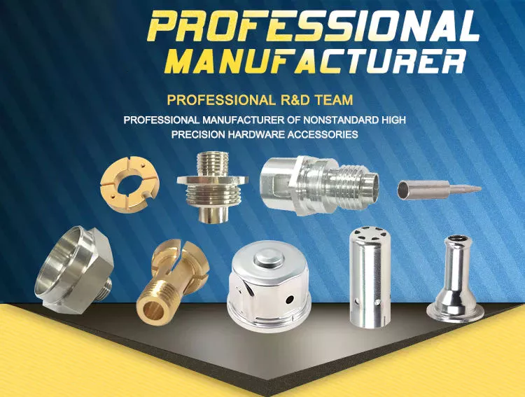
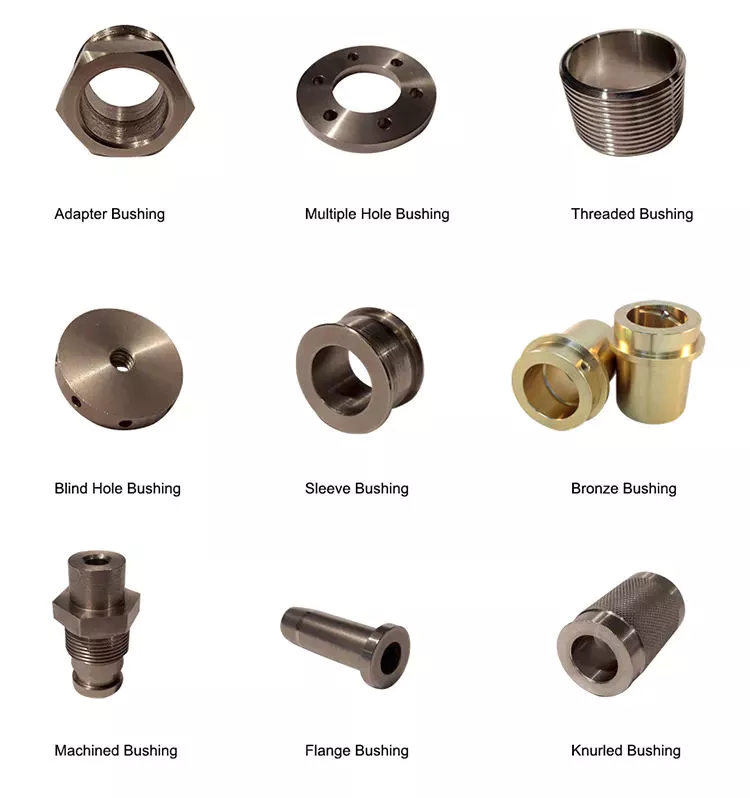
For rotating and sliding parts, bushings are an important part of the machine. Due to their anti-friction properties and load-carrying capacity, they are an important part of many different industrial processes. Bushings play a vital role in industries such as construction, mining, hydropower, agriculture, transportation, food processing and material handling. To learn more about the benefits of bushings, read on. You’ll be amazed how much they can help your business!
bushing

type

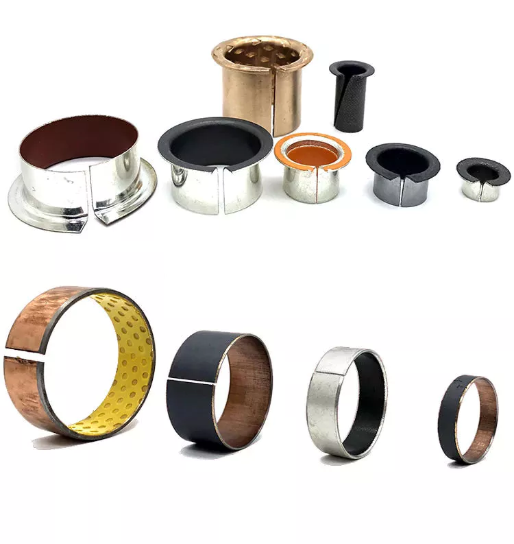
When comparing enclosure types, consider the material and how it will be used. Oilite bushings are made of porous material that draws lubricant into the liner and releases it when pressure is applied. These are manufactured using a sintered or powered metal process. Copper and tin are the most commonly used materials for making copper bushings, but there are other types of metal bushings as well.
Another popular type is the plain bearing. This type reduces friction between the rotating shaft and the stationary support element. This type provides support and load bearing while relying on soft metal or plastic for lubrication. Journal bearings are used to support the linear motion of the engine crankshaft in large turbines. They are usually babbitt or hydrodynamic with a liquid film lubricant between the 2 halves.
The oil-impregnated paper sleeve is made of high-quality kraft insulating paper. These bushings contain 2 layers of capacitor grading, with the innermost layer electrically connected to the mounting flange. These are mature processes and are widely used in different voltage levels. CZPT Electric (Group) Co., Ltd. provides UHV DC and AC oil-impregnated paper wall bushings for environmental control rooms.
Electrical bushings are used to transmit electricity. These can be transformers, circuit breakers, shunt reactors and power capacitors. The bushing can be built into the bushing or through the bushing. The conductors must be able to carry the rated current without overheating the adjacent insulation. A typical bushing design has a conductor made of copper or aluminum with insulation on all other sides. If the bushing is used in a circuit, the insulation needs to be high enough to prevent any leakage paths.
Voltage and current ratings of electrical bushings. Solid type electrical bushings typically have a center conductor and a porcelain or epoxy insulator. These bushings are used in small distribution transformers and large generator step-up transformers. Their test voltage is typically around 70 kV. Subsequent applications of this bushing may require a lower halfway release limit. However, this is a common type for many other applications.
bushing

application

Various industrial applications involve the use of casing. It is an excellent mechanical and chemical material with a wide range of properties. These compounds are also packaged according to national and international standards. Therefore, bushings are used in many different types of machines and equipment. This article will focus on the main industrial applications of casing. This article will also explain what a casing is and what it can do. For more information, click here. Casing application
Among other uses, bushing assemblies are used in aircraft and machinery. For example, a fuel tank of an aircraft may include baffle isolator 40 . The bushing assembly 16 serves as an interface to the fuel tank, allowing electrical current to flow. It can also be used to isolate 1 component from another. In some cases, bushing assemblies are used to provide a tight fit and reduce electrical resistance, which is important in circuits.
The benefits of casing go beyond reducing energy transmission. They reduce lubrication costs. If 2 metal parts are in direct contact, lubrication is required. Thus, the bushing reduces the need for lubrication. They also allow parts of the car to move freely. For example, rubber bushings may begin to deteriorate due to high internal temperatures or cold weather. Also, oil can affect their performance.
For example, bushing CTs in oil and gas circuit breakers are used as window current transformers. It consists of a toroidal core and secondary windings. The center conductor of the bushing acts as the single-turn primary of the BCT. By tapping the secondary winding, the ratio between primary and secondary can be changed. This information can be found on the asset nameplate.
Among other uses, bushings are used in diagnostic equipment. These components require precise positioning. Fortunately, air sleeves are perfect for this purpose. Their frictionless operation eliminates the possibility of misalignment. In addition, products based on porous media help minimize noise. A casing manufacturer can advise you on the best product for your equipment. Therefore, if you are looking for replacement bushings for your existing equipment, please feel free to contact Daikin.

Material

Dry ferrule cores were selected for study and examined under an Olympus polarizing microscope (BX51-P). Core slices showing layers of aluminum foil with a distance of approximately 2 cm between adjacent capacitor screens. The aluminum foil surface has a multi-layered structure with undulations due to shrinkage and crepe. Differences between the 2 types of foils are also revealed.
A typical metal bushing material consists of a high-strength metal backing and a solid lubricant. These materials have higher load-carrying capacity and low friction during operation. Additionally, they are precision machined to tight tolerances. They also offer better thermal conductivity and better fatigue resistance. The accuracy of the metal bushing is improved due to the re-machining process that takes place after the bearing is assembled. Additionally, metal bushing materials are more resistant to wear than plastic bushing materials.
Plastic bushings are relatively inexpensive and readily available off the shelf. Also, the price of custom plastic bushings is relatively low. However, they are not recommended for heavy duty applications. Plastics degrade under high loads and can damage mating parts. Also, if the plastic bushings are not manufactured accurately, they can become misaligned. These are just some of the reasons for choosing metal bushings over plastic.
A mechanically bonded bushing 40 is placed over the stabilizer bar and compressed into the outer sleeve/bracket assembly. The outer metal member includes slotted holes that compensate for the tolerance stacking between the first and second bushing assemblies. Pre-assembly allows the assembly plant to receive a complete assembly ready for vehicle assembly, rather than sub-assembly at the vehicle manufacturing plant.
bushing

cost

Control arm bushings are a major component of modern vehicle suspension systems. Damaged bushings can negatively affect the handling and performance of your car. Replacing bushings on a car can cost $200 to $500. While that’s pretty cheap for a handful of control bushings, replacing the entire suspension system could set you back over $1,200. Thankfully, if you want to repair or replace the bushing yourself, you can do it yourself for a fraction of the cost.
If you decide to replace the control arm bushing yourself, it’s best to shop around for the best price. Many auto parts stores offer cheaper bushings that you don’t have to spend a fortune on. Even if you don’t drive for years, rubber can degrade and create cracks in the material. These cracks can be as deep as three-8hs of an inch. This makes it dangerous to drive a car with damaged control arm bushings.
Hiring a mechanic might be a good idea if you don’t like doing the work yourself. You can save money and time by repairing the control arm yourself, but you may have to hire a mechanic to do the job. Replacing the front sway bar bushing alone can cost between $450 and $900. While these components are relatively inexpensive, you can replace them for a better-handling car.
In some cases, sizing the bushings is a more economical option, but if you want to replace your entire suspension system, it’s better to buy a brand new lower limit. You can even save labor by buying a replacement part fork with a good lower portion. In addition to improving your car’s handling and ride, new bushings will add to your car’s overall value. If you are not sure which parts you need, ask your mechanic for a quote.
While the cost of replacing control arm bushings is relatively low, it’s a good idea to compare quotes from multiple mechanics. By getting multiple quotes for the same repair, you can save as much as $50 to $100 on the total cost of your car. In addition to labor costs, parts and labor can vary, so shop around to find the mechanic best suited for your car. There’s no reason to settle for sub-par service when you can save $50 or more!

China factory CNC Processing Machinery Metal Stainless Steel Copper Brass Part for Engine Motorcycle     near me manufacturer China factory CNC Processing Machinery Metal Stainless Steel Copper Brass Part for Engine Motorcycle     near me manufacturer

China Standard CNC Turning Parts for Machinery with high quality

Product Description

CNC Turning Parts for Machinery

 Lost Wax Silica Sol Investment Stainless Steel Casting

Features:

1. Application: Auto part, Flange.

2. Material: 5140(40Cr), SAE1045, SAE1055, Stainless Steel or other material.

3. Main process:1> Investment casting;2> Deburring;3> Sandblasting;4> Machining;

Why HangZhou Evergreen?

1. 25 years of experience in casting and forging for European and U.S. markets.
2. OEM & ODM products range: Auto parts, Truck Parts, Engine parts, Agriculture equipment parts, Train parts, Hardware, etc.

3. Lost Wax Casting (Investment Casting) Material: 5140(40Cr), SAE1045(45# Steel), SAE1055(55# Steel), Staniless steel, Carbon Steel or other materials as you request.

4. Material Standard: ISO, GB, ASTM , AISI , DIN , BS, JIS.

5. Product weight: From 0.05~200kg;

6. Machining equipment: CNC, Lathe machine, Milling machine, Drilling machine, and so on;

7. Test equipment: Optical Spectrum Analyzer, CMM, Hardness test equipment, Tensile test machine;

8. Surface treatment: Blacking, Polishing, Anodize, Chrome plating, Zinc plating,Nickel plating, Tinting, Power coating, E-coating etc

9. Heat Treatment:  annealing , discharge, carbonization, tempering, normalization and surface tempering

Precision Machining Workshops and Equipments:  


Lost Wax Silica Sol Investment Stainless Steel Casting

HangZhou CZPT Machinery Co., Ltd started business since 1995, it has 2 subsidiary plants, and the headquarter located in HangZhou, a very famous CZPT city in China.

Our main business in metal products, and our product range mainly covers Metal work, Aluminum Casting, Investment/Precision casting steel, Sand casting, Forging, and so on. These products used in Wind power, Turbine, heavy duty Truck, Train, Engine, Agriculture equipment, Lighting, Marine and Mining machinery, Hardware, CZPT breeding, etc.

Capability & Capacity:

Our capability and production capacity as below:
1.  Capacity: 1> Al die casting: 3000~4000 ton per year; 2> Sand casting: 10000 ton per year; 3> Investment casting: 2000 ton per year; 4> Forging: 8000 ton per year.
2. Our metal work factory pass EN15085 & ISO3834 welding certificate
3.  Machining equipment: CNC, Lathe machine, Milling machine, Drilling machine, Grinding machine, and so on.
4.  Test equipment: Optical Spectrum Analyzer, CMM, Hardness test equipment, Tensile test machine.
5.  Surface treatment: Powder coating, Anodization, Chrome plating, Painting, Sand blasting, Galvanization.

Quality & Service:

Our quality philosophy is ” No Compromise“.

We have a diverse customer range CZPT over 30 countries and regions, including Germany, USA, Australia and Japan. We’re committed to serve our customer by providing quality products and services. For our original customers, we offer products and services that meet or exceed their expectations whenever needed. For our emerging market customers, we provide value-added, affordable products whenever possible.


                                 PROCESS TYPE                            MATERIAL STHangZhouRD
Sand Casting Green Sand Grey Iron, Ductile Iron, Malleable Iron, Brass, Bronze         ISO
        GB
      ASTM
       SAE       
        BS
        JIS
        DIN
        
Furan Resin Sand
Cold Harden Resin Sand
Investment casting       Sodium Silicone (Water galss) Stainless Steel, Carbon Steel, Special Alloy Steel Bronze, Brass, Aluminum
Lost wax casting
Forging                                                        Hot Forging Stainless Steel, Carbon Steel, Alloy Streel, Brass, Aluminum
Warm Forging
Cold Forging
Machining and other further processiong                 Stamping, cutting, welding, polishing,sand blasting…… All metal material

Applications of Our OEM Metal Parts:


Lead Screws and Clamp Style Collars

If you have a lead screw, you’re probably interested in learning about the Acme thread on this type of shaft. You might also be interested in finding out about the Clamp style collars and Ball screw nut. But before you buy a new screw, make sure you understand what the terminology means. Here are some examples of screw shafts:

Acme thread

The standard ACME thread on a screw shaft is made of a metal that is resistant to corrosion and wear. It is used in a variety of applications. An Acme thread is available in a variety of sizes and styles. General purpose Acme threads are not designed to handle external radial loads and are supported by a shaft bearing and linear guide. Their design is intended to minimize the risk of flank wedging, which can cause friction forces and wear. The Centralizing Acme thread standard caters to applications without radial support and allows the thread to come into contact before its flanks are exposed to radial loads.
The ACME thread was first developed in 1894 for machine tools. While the acme lead screw is still the most popular screw in the US, European machines use the Trapezoidal Thread (Metric Acme). The acme thread is a stronger and more resilient alternative to square threads. It is also easier to cut than square threads and can be cut by using a single-point threading die.
Similarly to the internal threads, the metric versions of Acme are similar to their American counterparts. The only difference is that the metric threads are generally wider and are used more frequently in industrial settings. However, the metric-based screw threads are more common than their American counterparts worldwide. In addition, the Acme thread on screw shafts is used most often on external gears. But there is still a small minority of screw shafts that are made with a metric thread.
ACME screws provide a variety of advantages to users, including self-lubrication and reduced wear and tear. They are also ideal for vertical applications, where a reduced frictional force is required. In addition, ACME screws are highly resistant to back-drive and minimize the risk of backlash. Furthermore, they can be easily checked with readily available thread gauges. So, if you’re looking for a quality ACME screw for your next industrial project, look no further than ACME.
screwshaft

Lead screw coatings

The properties of lead screw materials affect their efficiency. These materials have high anti-corrosion, thermal resistance, and self-lubrication properties, which eliminates the need for lubrication. These coating materials include polytetrafluoroethylene (PFE), polyether ether ketone (PEK), and Vespel. Other desirable properties include high tensile strength, corrosion resistance, and rigidity.
The most common materials for lead screws are carbon steel, stainless steel, and aluminum. Lead screw coatings can be PTFE-based to withstand harsh environments and remove oil and grease. In addition to preventing corrosion, lead screw coatings improve the life of polymer parts. Lead screw assembly manufacturers offer a variety of customization options for their lead screw, including custom-molded nuts, thread forms, and nut bodies.
Lead screws are typically measured in rpm, or revolutions per minute. The PV curve represents the inverse relationship between contact surface pressure and sliding velocity. This value is affected by the material used in the construction of the screw, lubrication conditions, and end fixity. The critical speed of lead screws is determined by their length and minor diameter. End fixity refers to the support for the screw and affects its rigidity and critical speed.
The primary purpose of lead screws is to enable smooth movement. To achieve this, lead screws are usually preloaded with axial load, enabling consistent contact between a screw’s filets and nuts. Lead screws are often used in linear motion control systems and feature a large area of sliding contact between male and female threads. Lead screws can be manually operated or mortised and are available in a variety of sizes and materials. The materials used for lead screws include stainless steel and bronze, which are often protected by a PTFE type coating.
These screws are made of various materials, including stainless steel, bronze, and various plastics. They are also made to meet specific requirements for environmental conditions. In addition to lead screws, they can be made of stainless steel, aluminum, and carbon steel. Surface coatings can improve the screw’s corrosion resistance, while making it more wear resistant in tough environments. A screw that is coated with PTFE will maintain its anti-corrosion properties even in tough environments.
screwshaft

Clamp style collars

The screw shaft clamp style collar is a basic machine component, which is attached to the shaft via multiple screws. These collars act as mechanical stops, load bearing faces, or load transfer points. Their simple design makes them easy to install. This article will discuss the pros and cons of this style of collar. Let’s look at what you need to know before choosing a screw shaft clamp style collar. Here are some things to keep in mind.
Clamp-style shaft collars are a versatile mounting option for shafts. They have a recessed screw that fully engages the thread for secure locking. Screw shaft clamp collars come in different styles and can be used in both drive and power transmission applications. Listed below are the main differences between these 2 styles of collars. They are compatible with all types of shafts and are able to handle axial loads of up to 5500 pounds.
Clamp-style shaft collars are designed to prevent the screw from accidentally damaging the shaft when tightened. They can be tightened with a set screw to counteract the initial clamping force and prevent the shaft from coming loose. However, when tightening the screw, you should use a torque wrench. Using a set screw to tighten a screw shaft collar can cause it to warp and reduce the surface area that contacts the shaft.
Another key advantage to Clamp-style shaft collars is that they are easy to install. Clamp-style collars are available in one-piece and two-piece designs. These collars lock around the shaft and are easy to remove and install. They are ideal for virtually any shaft and can be installed without removing any components. This type of collar is also recommended for those who work on machines with sensitive components. However, be aware that the higher the OD, the more difficult it is to install and remove the collar.
Screw shaft clamp style collars are usually one-piece. A two-piece collar is easier to install than a one-piece one. The two-piece collars provide a more effective clamping force, as they use the full seating torque. Two-piece collars have the added benefit of being easy to install because they require no tools to install. You can disassemble one-piece collars before installing a two-piece collar.
screwshaft

Ball screw nut

The proper installation of a ball screw nut requires that the nut be installed on the center of the screw shaft. The return tubes of the ball nut must be oriented upward so that the ball nut will not overtravel. The adjusting nut must be tightened against a spacer or spring washer, then the nut is placed on the screw shaft. The nut should be rotated several times in both directions to ensure that it is centered.
Ball screw nuts are typically manufactured with a wide range of preloads. Large preloads are used to increase the rigidity of a ball screw assembly and prevent backlash, the lost motion caused by a clearance between the ball and nut. Using a large amount of preload can lead to excessive heat generation. The most common preload for ball screw nuts is 1 to 3%. This is usually more than enough to prevent backlash, but a higher preload will increase torque requirements.
The diameter of a ball screw is measured from its center, called the ball circle diameter. This diameter represents the distance a ball will travel during 1 rotation of the screw shaft. A smaller diameter means that there are fewer balls to carry the load. Larger leads mean longer travels per revolution and higher speeds. However, this type of screw cannot carry a greater load capacity. Increasing the length of the ball nut is not practical, due to manufacturing constraints.
The most important component of a ball screw is a ball bearing. This prevents excessive friction between the ball and the nut, which is common in lead-screw and nut combinations. Some ball screws feature preloaded balls, which avoid “wiggle” between the nut and the ball. This is particularly desirable in applications with rapidly changing loads. When this is not possible, the ball screw will experience significant backlash.
A ball screw nut can be either single or multiple circuits. Single or multiple-circuit ball nuts can be configured with 1 or 2 independent closed paths. Multi-circuit ball nuts have 2 or more circuits, making them more suitable for heavier loads. Depending on the application, a ball screw nut can be used for small clearance assemblies and compact sizes. In some cases, end caps and deflectors may be used to feed the balls back to their original position.

China Standard CNC Turning Parts for Machinery     with high qualityChina Standard CNC Turning Parts for Machinery     with high quality