Tag Archives: machining cnc

China Good quality Aluminum 5 Axis CNC Machining Stainless Steel Parts with Best Sales

Product Description

 aluminum 5 axis cnc machining stainless steel parts


Product Description

      
         The auto hardware accessories we produce have reached cooperation with famous Japanese auto suppliers for many years. In terms of delivery, we will deliver on time and without delay. Special-shaped accessories are unique, and we have a complete supply chain. The system, from mold manufacturing, to raw material purchase, to production, has a complete process, which enables our production to proceed smoothly and quickly. In addition, production workers can implement a shift system for uninterrupted production to ensure delivery.


Product Name : Sheet metal fabrication 
Our Service: OEM/ODM sheet metal fabrication
Material: Aluminium Profile/Aluminum Plate/Stainless Steel /SGCC 
Bending: 0 ~ +/-0.1mm 
CNC machining: 0 ~ +/-0.1mm 
Delivery time: 3-7 days for sample. Mass production depends on the quantity.

Production Technology


Our Advantages


Detailed Photos


Packaging & Shipping


     In terms of product packaging, we adopt a more careful packaging method to protect metal accessories more safely. Due to the humid air at sea and high salt content, it is more corrosive to metal products. Buyers often store these products in the warehouse after they buy them back, so we make the hardware accessories less likely to be exposed to sea air during the shipping process through careful packaging, thereby avoiding the problem of rust. We tend to put moisture-proof agents in cartons, wooden boxes, and iron boxes. After packaging, it is sealed with plastic film to keep out the air.


Certifications


Company Profile

         HangZhou Lianrun Hardware Products Co., Ltd. is a custom metalworking manufacturer specializing in metal stamping, deep drawing stamping and machining. Has an independent export qualification and an experienced foreign trade team. Since 2003, the company has been providing all customers with customized services for auto parts and accessories, hardware tool parts, metal crafts. Our team will help you reduce tooling investment and reduce part cost according to your requirements. Please send us your design drawings and samples for our prompt and high quality quotation. Bring you high-efficiency production capacity through modern workshops and workers.


FAQ

1.Q:Company products can be customized according to the corresponding specifications provided by us?
        Yes,We can provide customized service.

2.Q:Product material can guarantee?
        Completely, with special certification.

3.Q:Product delivery, delivery time will be long?
       
We will control the delivery with high quality and efficiency within the time limit you require.

4.Q:Are you a factory or a trading company?
       
We are a custom factory.

5.Q:How long is your delivery time?
       
Our delivery time is usually 10 to 25 days, or depending on the quantity.

6.Q:What are the payment terms?
       
30% T / T in advance, balanced before shipment.We provide photos, videos and even third parties to check.

7.Q:How do you ensure quality control?
       
100% quality inspection before packaging, the pass rate is over 99.5%.

How to Assemble a Pulley System

A pulley is a wheel that rotates on a shaft or shaft to support the movement of a taut cable. Pulleys allow power to be transmitted from the shaft to the cable.
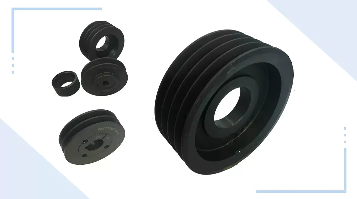
pulley

Simple pulley

The simplest theory of operation of a pulley system assumes that the rope and weight are weightless and that the rope and pulley are not stretched. Since the force on the pulley is the same, the force on the pulley shaft must also be zero. Therefore, the force exerted on the pulley shaft is also distributed evenly between the 2 wires passing through the pulley. The force distribution is shown in Figure 1.
The use of simple pulleys is as old as history. Before the Industrial Revolution, people relied on muscle strength to carry heavy loads. Pulleys, levers and ramps make this possible. Today, we can see pulleys in a variety of systems, from exercise equipment to garage doors, and even rock climbers use them to help them reach greater heights. As you can see, these simple machines have been around for centuries and are used in everyday life.
Another simple pulley system is the pulley system. In this system, there is a fixed pulley at the top and a movable pulley at the bottom. The 2 pulleys are connected by a rope. This combination reduces the amount of work required to lift the load. Additionally, the ropes used in this system are usually made of rope and woven through the individual wheels of the pulley drum.
A pulley is an ingenious device that distributes weight evenly and can be used to lift heavy objects. It is easy to build and can be easily modified for a wide range of activities. Even young children can make their own with very few materials. You can also use simple household items such as washing machines, thin textbooks and even chopsticks. It’s very useful and can be a great addition to your child’s science and engineering activities.
The simplest pulley system is movable. The axis of the movable pulley can move freely in space. The load is attached to 1 end of the pulley and the other end to the stationary object. By applying force on the other end of the rope, the load is lifted. The force at the other end of the rope is equal to the force at the free end of the pulley.
Another form of pulley is the compound pulley. Compound pulleys use 2 or more wheels to transmit force. Compound pulleys have 2 or more wheels and can lift heavier objects. Dim is POLE2.
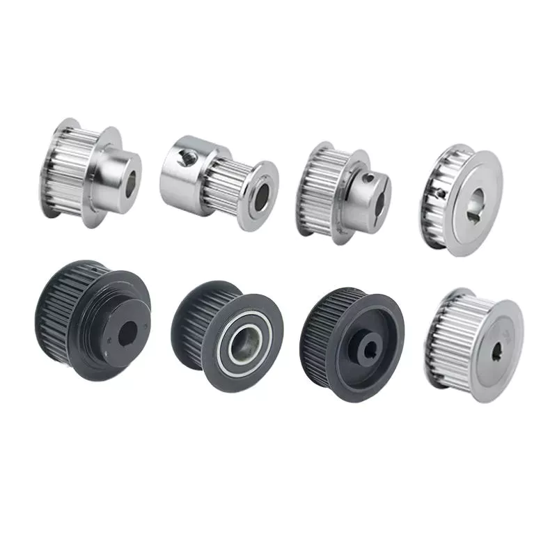
pulley

tapered pulley

It is important to clean and align the bolt holes before assembling the tapered pulley. The screws should be lubricated and the threads cleaned before installation. To install the pulley, insert it into the shaft keyway. The keyway should be aligned with the shaft hole to prevent foreign matter from entering the pulley. Then, alternately tighten the bolts until the pulley is tightened to the desired torque.
A tapered pulley is a basic structure. The pulley belt is arranged across 4 steps. Installed between the headstock casting and the main shaft, it is often used in the paper industry. It integrates with printing machinery and supports assembly lines. These pulleys are also available in metric range options, eliminating the need for ke-waying or re-drilling. They are easy to install, and users can even customize them to suit their needs.
CZPT Private Limited is a company that provides unique products for various industries. This large product is used for many different purposes. Also, it is manufactured for industrial use. The company’s website provides detailed specifications for the product. If you need a tapered pulley, contact a company in your area today to purchase a quality product!
Tapered pulleys are vital to paper mill machinery. Its special design and construction enable it to transmit power from the engine source to the drive components. The advantages of this pulley include low maintenance costs and high mechanical strength. Cone wheel diameters range from 10 inches to 74 inches. These pulleys are commonly used in paper mills as they offer low maintenance, high mechanical strength and low wear.
A tapered sleeve connects the pulley to the shaft and forms an interference fit connector. The taper sleeve is fixed on the shaft with a key, and the corresponding inner hole is fixed on the shaft with a key. These features transmit torque and force to the pulley through friction. This allows the tapered pulley to move in a circular motion. The torque transfer characteristics of this pulley are most effective in high speed applications.
The sleeve is the most important part when assembling the tapered pulley. There is an 8-degree taper inside the cone, which is closely connected to the inner surface of the pulley. Taper sleeves and pulleys are interchangeable. However, tapered pulleys can be damaged after prolonged use.
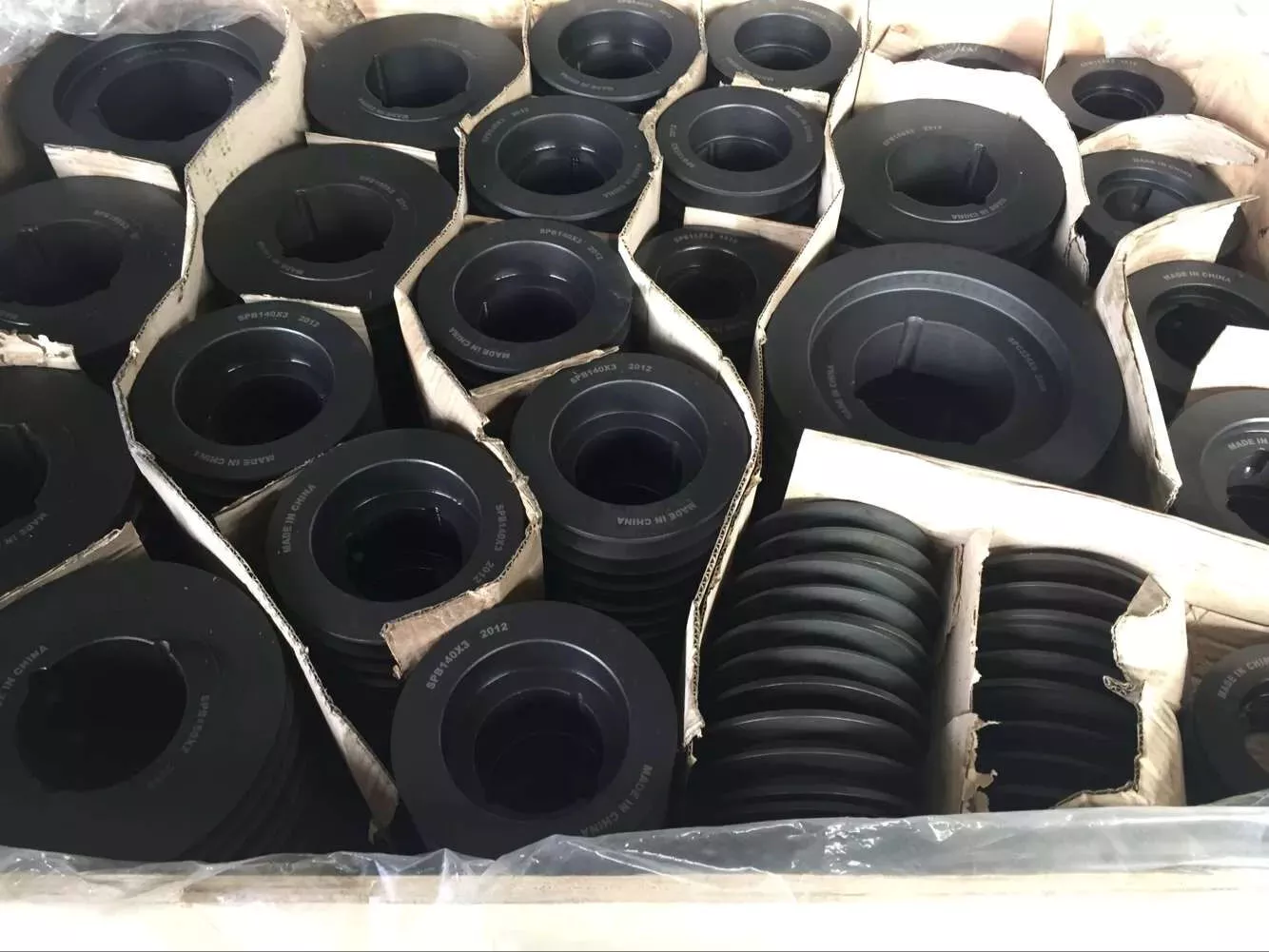
pulley

pulley pulley system

A pulley pulley system is a great way to move heavy objects. These systems have been around for centuries, dating back to the ancient Greeks. This simple mechanism enables a person to lift heavy objects. These blocks are usually made of rope, and the number of turns varies for different types of rope. Some blocks have more cords than others, which creates friction and interferes with the easy movement of the lifting system.
When using a pulley pulley, the first thing to decide is which direction to pull. Unfavorable rigging means pulling in the opposite direction. In theory, this method is less efficient, but sometimes requires a certain amount of work space. The benefit is that you will increase the mechanical advantage of the pulley by pulling in the opposite direction. So the interception and tackle system will give you more of a mechanical advantage.
Pulley pulleys are an excellent choice for lifting heavy objects. The system is simple to install and users can easily lift objects without extensive training. Figure 3.40 shows a pulley in action. In this photo, the person on the left is pulling a rope and tying the end of the rope to a weight. When the rope is attached to the load, the rope will be pulled over the pulley and pulley.
The blocks on the blocks are attached to the ends of the rope. This creates unique lifting advantages compared to single-line systems. In Figure 3, the tension of each thread is equal to one-third of the unit weight. When the rope is pulled over the pulley, the force is divided equally between the 2 wires. The other pulley reverses the direction of the force, but that doesn’t add any advantage.
Use pulleys to reduce traction and load. The weight of the load has not changed, but the length of the rope has increased. Using this method, lifting the load by pulling the rope 4 times reduces the force required to lift 1 foot. Likewise, if the pulley system had 4 pulleys instead of three, the length of the rope would be tripled.
The system can transmit loads in any direction. Rope length is determined by multiplying the distance from the fixed block to the load by the mechanical advantage. If the mechanical advantage is 3:1, then passing the rope through the pulley 3 times will produce the required traction distance. Also, the length of the rope will depend on the mechanical advantage, so if the load is 3 times the length of the rope, it will be more than 3 times the required length.

China Good quality Aluminum 5 Axis CNC Machining Stainless Steel Parts     with Best SalesChina Good quality Aluminum 5 Axis CNC Machining Stainless Steel Parts     with Best Sales

China Good quality Customized CNC Aluminum Machining Parts of Motor Precision Tractor Valve Pump Vehicle Heavy Truck Support with Best Sales

Product Description

Factory Equipment:
Sample Exhibition:

Our Commitment:

  1. Advanced processing equipment
  2. All-round processing technology
  3. Timely delivery of precision machined parts
  4. Meet customer requirements
  5. To provide customers with defect-free parts

The custom machining services that we can offer:

  1. CNC Machining
  2. Casting
  3. Fabrication
  4. Turning
  5. Milling
  6. Stamping
  7. Forging
  8. Welding

We are committed to ensure to complete your custom projects as below:

  1. Within the timeframe
  2. Within the budget
  3. Meeting the quality standard

We can design and make precision parts according to customers’ samples, drawing and AutoCAD or Pro/E file.
Company Qualification:

Types of pulleys and their advantages and disadvantages

There are several types of pulleys. Learn the basic equations of the pulley system. Then learn about the different uses for pulleys. The disadvantages of using pulleys will be covered. Knowing these, you can buy the pulley that suits your needs. Here are some of the best pulley types and their pros and cons.
pulley

Basic equations of pulley systems

A pulley system is a mechanism that allows 2 blocks of a certain mass to be connected by a taut rope. The acceleration of each block is the same in magnitude and direction. The external force acting on each block is the weight of the block (10g) and the tension in the string. The tension between the 2 blocks is the total tension and the force acting on the pulley is the weight of the 2 blocks.
This simple mechanism uses 2 simple equations to explain how the system works. First, the mass of the weight on both sides of the pulley must be the same. When the weight is forced to move, the rope tightens and the second pulley descends. The weight is also attached to the second pulley and must be the same distance as the first pulley. This will result in a speed ratio of 2 times the distance covered by the first pulley.
Second, we have to calculate the force required to lift the object. The lower mass is supported by a wire configuration passing through all pulleys, while the uppermost pulley is used to apply the force. The lower block is used to support the weight. The applied force needs to travel a distance nx to move the weight. This distance, called MA, can be written as:
Once we have gathered the necessary information, we can apply the calculations to the pulley system. We can also use the Mechanical Advantage Calculator to calculate the force on the anchor. To do this, we must apply a force to the load as well as to the pulley itself. Using this equation, we can calculate the force required by the load to lift the load.
pulley

Types of pulleys

There are 3 basic types of pulleys: movable, fixed and compound. Both types of pulleys translate the force applied to them. The ideal mechanical advantage of pulleys is two. This is because a single movable pulley only doubles the force, whereas a compound pulley doubles or triples the force. This type of pulley is often used with other types of pulleys.
Movable pulls move with the weight of the load, and the force pulling them increases on the lift side. They are often found in utility elevators and construction cranes. These systems are very simple, inexpensive and quiet to use. The force required to lift the object depends on the mechanical advantage of the system. The 2 most common types of pulleys are listed below. Let’s take a closer look at each one.
V-shaped pulleys are used in vehicles and electric motors. These pulleys require a “V” belt to function properly. Some have multiple “V” grooves to avoid slipping. They are used in heavy duty applications to reduce the risk of power slip. These pulleys also have more than 1 “V” groove. V-belt pulleys are commonly used in vehicles and electric motors.
Composite pulleys are made from more than 1 type of cable or rope wrapped around the wheel. They can be fixed or hinged and are usually made of stainless steel or bronze. Composite pulleys have multiple layers and can be a single unit or many different components. There are 3 main types of pulleys: fixed pulleys and composite pulleys. These are the most common types. Almost every type of pulley is used for some type of application.
Fixed pulleys have 1 advantage over movable pulleys: they change direction as the weight of the load increases. They are typically used in heavy construction equipment. Gun tackles, patio tackles, and stationary tackles are examples of equipment that use a pulley mechanism. These devices are very common and can be found on most modern construction sites. They provide great convenience for lifting large loads.

application

What are the applications of pulleys? Simply put, a pulley is a mechanical device that transforms a difficult task into an easier one. It consists of ropes and pulleys. It is usually used to lift objects. Usually, people wrap a rope around a pulley and pull up to lift the object. One disadvantage of using pulleys is that they require the same force as lifting the object directly.
One of the most popular applications of pulleys is lifting heavy objects. They help people pull up heavy objects and blocks. The system can also be used in seeders, lifts, grinders, etc. Other applications include raising flags, loading cargo, pulling curtains and rock or mountain climbing. Students can learn about the various uses of pulleys and the physics behind them.
Pulleys can be made of many different materials, depending on the application. Some are movable, which means they move with the object they are used to lift. This pulley system can be made of nylon, wire rope or fiber material. The best part about these systems is that they are easy to install and maintain. For a better grasp, use the guide or video tutorial to learn more about the pulley system and how it works.
Tapered pulleys are common in paper mills. They are high-quality pulleys that transmit power to connected parts. They can be dynamic or static and have different balances. Because pulley systems are highly customized, most industrial applications require systems designed specifically for specific applications. In this way, the system is safe, simple and inexpensive. The benefits of this design are endless.
The most common use of pulleys is for motor drives. They are used to minimize noise by applying force to the shaft to reduce the workload. They are also less expensive than gears and do not require lubrication. Furthermore, they can change the direction of the applied force. They are also less expensive than gears and are often used with other components. A screw is a cylindrical member with helical ribs used to connect something.
pulley

shortcoming

Although the pulley system makes it easier to move heavy objects, it still has some drawbacks. When using a pulley system, you must remember that the force required to lift the weight increases with the number of cycles. In addition, the distance between the puller and the heavy object increases, which may lead to accidents. Also, moving heavy objects can be tricky if the rope slips. Pulley systems are not very expensive and can be easily assembled. However, it does require a lot of space.
First, it is not efficient. Besides being inefficient, pulleys produce different forces at different speeds. Fixed pulleys use more force than the load, while movable pulleys move with the load. A movable pulley requires less force than a fixed pulley, but the combined system travels a long distance. Therefore, this method is not as efficient as the fixed method.
Pulleys are not only used in industrial processes. You can see them in various places in your daily life. For example, large construction cranes use pulleys to lift heavy loads. Even flagpoles, blinds, clotheslines, ziplines, motors and climbing equipment use pulleys. Still, despite their advantages, the disadvantages are not too serious.
Another disadvantage of the pulley is its wear and tear. While a pulley’s housing is theoretically infinite, its bearings and locking components typically wear out over time. To overcome this problem, a new bearing and locking assembly can be installed. No need to replace the housing and shaft, the entire assembly can be re-bonded and painted to replicate the original look. Alternatively, the pulley can be replaced with a new housing and shaft.
Using pulleys can also reduce the advantage of pulleys. On the other hand, interception and tackle is a system in which 2 pulleys are connected to each other using ropes. Unlike pulleys, pulley pulley systems can be adjusted in the direction of travel and can move heavy loads up to 4 times their force when used in hydraulic lifts.

China Good quality Customized CNC Aluminum Machining Parts of Motor Precision Tractor Valve Pump Vehicle Heavy Truck Support     with Best SalesChina Good quality Customized CNC Aluminum Machining Parts of Motor Precision Tractor Valve Pump Vehicle Heavy Truck Support     with Best Sales

China high quality High Precision Manufacturing CNC Metal Machining Service Aluminium Mlling Tractor Spare Parts with Great quality

Product Description

High Precision Manufacturing CNC metal machining service Aluminium mlling Tractor Spare Parts

1.Product Parameter

Factory: Custom 3 4 5 Axis CNC Machining Milling Service CNC Machined Parts Aluninum Stainless Meatl Parts
Production Description High Precision Manufacturing CNC metal machining service Aluminium mlling Tractor Spare Parts
Processing Machining, Turning, Milling, Grinding, Wire-EDM,Fabrication service etc.
Material for CNC Machining processing 1) Aluminum – AL 6061-T6, 6063, 7075-T,5083,6063,6082,5052,2A12 etc.
2) Stainless steel – SS 201,SS301 SS303,SS304,SS316L, SS416L,17-4(SUS630),440C, 430 etc.
3) Steel – 4140,4340,Q235, Q345B,20#,Cr12MoV,D2,A2,4140,4150,P20,S136,M2,O2, SKD11,CRS, etc.
4) Titanium – TA1,TA2/GR2, TA4/GR5, TC4, TC18 etc.
5) Brass – C36000 (HPb62), C37700 (HPb59), C26800 (H68), C22000(H90) etc.
6) Copper – bronze,Phosphor Bronze, Magnesium alloy,  etc.
7) Plastic – Peek, Nylon, G-10, Acrylic,Anti-Static Acetal Tan (Tecaform SD) , PC,ABS, etc.
8) Food class ,Medical class- such as POM, Delrin, etc.
9) Aerospace class – PEI+30%GF,PEEK+30%GF,PC+30%GF,PU,PTFE,PE,PVC etc.
10) Rollyu Precision handles many other type of materials, please kindly contact us if your required material is not listed above.
Finish For Aluminum parts – Clear anodized, Color anodized, Hard anodized, Sandblasting, Chemical film, Brushing, Polishing, Painting, Silk screen printing,Etching,  Laser marking, etc.
For Stainless steel parts  – Polishing, Passivation,PVD, Sandblasting, Black oxide, Electrophoresis black, Painting, Silk screen printing,Etching,  Laser marking, etc.
For Steel parts – Polishing, Black oxide, Nickel /Zinc/Gold/ Chrome/Silver plating, Carburized, Powder coating,electrophoresis, QPQ(Quench-Polish-Quench), Heat treatment,
Painting, Silk screen printing,Etching,  Laser marking, etc. etc.
For Brass parts – Nickel /Zinc/Gold/ Chrome/Silver/Titanium plating, Electrophoresis black, Powder coating,Painting, Silk screen printing,Etching,  Laser marking, etc. 
For Plastic parts – Plating (ABS), Brushing (Acylic),Painting, Silk screen printing,Etching,  Laser marking, etc.
HangZhou Hongrunshuo Precision handles many other type of finish, please kindly contact us if your required finish is not listed above.
Tolerance Minimum tolerance +/- 0.05mm (+/- 0.0005″)
Surface roughness  Ra 0.1~3.2
Drawing format Pro-e/UG/PDF/DWG/DXF/Solidworks, etc.
Testing equipment CMM (Coordinate Measuring Machine),Height gauge, Caliper,  Hardness tester, Roughness tester, Projector machine, Pin/Angle/Block/Plug/Thickness/Thread/Radius  gauge,etc. 
MOQ 1 piece
Lead time 2 weeks after received order.
Certificate ISO9001, ISO13485.
Inspection processing IQC,IPQC, FQC, QA.
Capacity CNC turning work range: φ0.5mm-φ650mm*600mm.
CNC milling work range: 880mm*1300mm*600mm.
Application Automation, Medical device, Consumer Electronics, Security, IoT, Energy, etc. 

2. Who we are ?

3.  Our Equipments


4.  Strict  Quality Control Flow

5.  More Products


6.  Package & Shipment

7. FAQ

Q1: Are you a trading company or a factory ?
A1: We are a manufacturer specialized in precision parts OEM&ODM, Machining parts, Plastic parts, Silicone and rubber parts, Heat sink, sheet metal fabrication as well as Sub-assembly.

Q2: Do you accept to manufacture the customized products based on our design?
A2: Yes, we are a professional factory with an experienced engineering team, would like to provide the OEM service.

Q3: How can I get the quotation?
A3: We will offer you the quotation within 24 working hours after receiving your detailed information. In order to quote you faster and more accurate, please provide us the following information together with your inquiry:
1) CAD or 3D Drawings
2) Tolerance.
3) Material requirement
4) Surface treatment
5) Quantity (per order/per month/annual)
6) Any special demands or requirements, such as packing, labels, delivery,etc.

Q4: Will my drawings be safe after sending to you?
A4: Sure, we will keep them well and not release to others without your permission.

Q5: How long is the lead-time for a mold and plastic parts, machining parts, sheet metal fabrication?
A5: It all depends on the mold (parts) size and complexity.
Normally, the lead time is 18-20 days for molds, 15-20 days for plastic parts. If the molds are very simple and not big, we can work out within 15 days.
The lead time for machining parts is around 2-4 weeks.
For sheet metal fabrication the lead time is around 3-5 weeks.

Q6: I have no 3D drawing, how should I start the new project?
A6: You can supply us the sample or provide us the product sizes and let us know the detailed requirements, our engineers will help you to work out the 3D drawing.

Q7: If you make poor quality goods, will you refund our fund?
A7: As a matter of fact, we won’t take a chance to do poor quality products. Meanwhile, we manufacture good-quality products until your satisfaction.

Q8: Is it possible to know how are my products going on without visiting your factory?
A8: We will offer a detailed production schedule and send weekly reports with digital pictures and videos which show the machining or the plastic injection progress.


The benefits of rubber bushings and how they work

If you have experienced increased vibration while driving, you know the importance of replacing the control arm bushings. The resulting metal-to-metal contact can cause annoying driving problems and be a threat to your safety. Over time, the control arm bushings begin to wear out, a process that can be exacerbated by harsh driving conditions and environmental factors. Additionally, larger tires that are more susceptible to bushing wear are also prone to increased vibration transfer, especially for vehicles with shorter sidewalls. Additionally, these plus-sized tires, which are designed to fit on larger rims, have a higher risk of transmitting vibrations through the bushings.
bushing

rubber

Rubber bushings are rubber tubes that are glued into the inner or outer curve of a cylindrical metal part. The rubber is made of polyurethane and is usually prestressed to avoid breaking during installation. In some cases, the material is also elastic, so it can slide. These properties make rubber bushings an integral part of a vehicle’s suspension system. Here are some benefits of rubber bushings and how they work.
Rubber bushings are used to isolate and reduce vibration caused by the movement of the 2 pieces of equipment. They are usually placed between 2 pieces of machinery, such as gears or balls. By preventing vibrations, rubber bushings improve machine function and service life. In addition to improving the overall performance of the machine, the rubber bushing reduces noise and protects the operator from injury. The rubber on the shock absorber also acts as a vibration isolator. It suppresses the energy produced when the 2 parts of the machine interact. They allow a small amount of movement but minimize vibration.
Both rubber and polyurethane bushings have their advantages and disadvantages. The former is the cheapest, but not as durable as polyurethane. Compared to polyurethane, rubber bushings are a better choice for daily commutes, especially long commutes. Polyurethane bushings provide better steering control and road feel than rubber, but can be more expensive than the former. So how do you choose between polyurethane and rubber bushings?

Polyurethane

Unlike rubber, polyurethane bushings resist high stress environments and normal cycling. This makes them an excellent choice for performance builds. However, there are some disadvantages to using polyurethane bushings. Read on to learn about the advantages and disadvantages of polyurethane bushings in suspension applications. Also, see if a polyurethane bushing is suitable for your vehicle.
Choosing the right bushing for your needs depends entirely on your budget and application. Softer bushings have the lowest performance but may have the lowest NVH. Polyurethane bushings, on the other hand, may be more articulated, but less articulated. Depending on your needs, you can choose a combination of features and tradeoffs. While these are good options for everyday use, for racing and hardcore handling applications, a softer option may be a better choice.
The initial hardness of the polyurethane bushing is higher than that of the rubber bushing. The difference between the 2 materials is determined by durometer testing. Polyurethane has a higher hardness than rubber because it does not react to load in the same way. The harder the rubber, the less elastic, and the higher the tear. This makes it an excellent choice for bushings in a variety of applications.

hard

Solid bushings replace the standard bushings on the subframe, eliminating axle clutter. New bushings raise the subframe by 0.59″ (15mm), correcting the roll center. Plus, they don’t create cabin noise. So you can install these bushings even when your vehicle is lowered. But you should consider some facts when installing solid casing. Read on to learn more about these casings.
The stiffest bushing material currently available is solid aluminum. This material hardly absorbs vibrations, but it is not recommended for everyday use. Its stiffness makes it ideal for rail vehicles. The aluminum housing is prone to wear and tear and may not be suitable for street use. However, the solid aluminum bushings provide the stiffest feel and chassis feedback. However, if you want the best performance in everyday driving, you should choose a polyurethane bushing. They have lower friction properties and eliminate binding.
Sturdy subframe bushings will provide more driver feedback. Additionally, it will strengthen the rear body, eliminating any movement caused by the subframe. You can see this structural integration on the M3 and M4 models. The benefits of solid subframe bushings are numerous. They will improve rear-end handling without compromising drivability. So if you plan to install a solid subframe bushing, be sure to choose a solid bushing.
bushing

Capacitor classification

In the circuit, there is a high electric field on both sides of the capacitor grading bushing. This is due to their capacitor cores. The dielectric properties of the primary insulating layer have a great influence on the electric field distribution within the bushing. This article discusses the advantages and disadvantages of capacitor grade bushings. This article discusses the advantages and disadvantages of grading bushings for capacitors in DC power systems.
One disadvantage of capacitor grading bushings is that they are not suitable for higher voltages. Capacitor grading bushings are prone to serious heating problems. This may reduce their long-term reliability. The main disadvantage of capacitor grading bushings is that they increase the radial thermal gradient of the main insulation. This can lead to dielectric breakdown.
Capacitor grading bushing adopts cylindrical structure, which can suppress the influence of temperature on electric field distribution. This reduces the coefficient of inhomogeneity of the electric field in the confinement layer. Capacitor grading bushings have a uniform electric field distribution across their primary insulation. Capacitive graded bushings are also more reliable than nonlinear bushings.
Electric field variation is the most important cause of failure. The electrode extension layer can be patterned to control the electric field to avoid flashover or partial discharge of the primary insulating material. This design can be incorporated into capacitor grading bushings to provide better electric fields in high voltage applications. This type of bushing is suitable for a wide range of applications. This article discusses the advantages and disadvantages of capacitor grade bushings.

Metal

When choosing between plastic and metal sleeves, it is important to choose a product that can handle the required load. Plastic bushings tend to deteriorate and often crack under heavy loads, reducing their mechanical strength and service life. Metal bushings, on the other hand, conduct heat more efficiently, preventing any damage to the mating surfaces. Plastic bushings can also be made with lubricating fillers added to a resin matrix.
Plastic bushings have many advantages over metal bushings, including being cheap and versatile. Plastic bushings are now used in many industries because they are inexpensive and quick to install. These plastic products are also self-lubricating and require less maintenance than metals. They are often used in applications where maintenance costs are high or parts are difficult to access. Also, if they are prone to wear and tear, they are easy to replace.
Metal bushings can be made of PTFE, plastic or bronze and are self-lubricating. Graphite plugs are also available for some metal bushings. Their high load capacity and excellent fatigue resistance make them a popular choice for automotive applications. The bi-metallic sintered bronze layer in these products provides excellent load-carrying capacity and good friction properties. The steel backing also helps reduce processing time and avoids the need for additional pre-lubrication.
bushing

plastic

A plastic bushing is a small ball of material that is screwed onto a nut or locknut on a mechanical assembly. Plastic bushings are very durable and have a low coefficient of friction, making them a better choice for durable parts. Since they do not require lubrication, they last longer and cost less than their metal counterparts. Unlike metal bushings, plastic bushings also don’t scratch or attract dirt.
One type of acetal sleeve is called SF-2. It is made of metal alloy, cold rolled steel and bronze spherical powder. A small amount of surface plastic penetrated into the voids of the copper spherical powder. Plastic bushings are available in a variety of colors, depending on the intended application. SF-2 is available in black or grey RAL 7040. Its d1 diameter is sufficient for most applications.
Another acetal sleeve is UHMW-PE. This material is used in the production of bearings and in low load applications. This material can withstand pressures from 500 to 800 PSI and is widely available. It is also self-lubricating and readily available. Due to its high resistance to temperature and chemical agents, it is an excellent choice for low-load industrial applications. If you’re in the market for an alternative to nylon, consider acetal.
Positional tolerances in many automotive components can cause misalignment. Misaligned plastic bushings can negatively impact the driver’s experience. For example, the cross tubes used to mount the seat to the frame are made by a stamping process. The result is a misalignment that can increase torque. Also, the plastic bushing is pushed to 1 side of the shaft. The increased pressure results in higher friction, which ultimately results in a poor driving experience.
v
China high quality High Precision Manufacturing CNC Metal Machining Service Aluminium Mlling Tractor Spare Parts     with Great qualityChina high quality High Precision Manufacturing CNC Metal Machining Service Aluminium Mlling Tractor Spare Parts     with Great quality

China Professional CNC Machining Orange RC Racing Clutch Parts near me manufacturer

Product Description

CNC Machining Orange RC Racing Clutch Parts

About Us:
HangZhou CZPT Hardware products Co., Ltd. is located in HangZhou City, ZheJiang Province of China. We has extremely convenient transportation conditions. 

Established in 2014, our company now covers an area of more than8000 square meters, and have over 100 full time employees. 
We are a professional manufacturer and have 7 years experience in precisely manufacturing and processing machinery parts and components, especially precision CNC machined items. 
We has over 120 units of manufacturing equipments, including CNC lathes, machine centers, grinding machines, etc. We can provide precision machining services, such as CNC milling, turning, drilling, tapping, stamping, anodizing, knurling, die casting, sand casting, and forging. 
We can machine many kinds of materials, including carbon steel, stainless steel, aluminum, brass, bronze, Iron, plastic, etc. 
With advanced technology support and management concepts, CZPT has developed steadily and quickly. Since establishment, we have been cooperating with many domestic and overseas enterprises. Most of our products are shipped to international clients. At present, we have long-term clients from USA, Europe, Middle East, Africa, Japan and Korea. With first-class technology, competitive pricing, superior quality, dependable on-time delivery, and outstanding customer service, we have won the full recognition and high appreciation from our clients. 

*How to receive an online quotation?
Please send us your 3D drawing/2D drawing for us to check all dimension

  1. Specify the required material, finish, quantity information in the email, we will handle it for you once receiving it soon!

Note: Workable 3D Drawing Formats: STEP/IGS/X_T/STL/SOLIDWORKS etc, 2D Drawing with PDF will do.

*Product Description:

Advantages »Reliable CNC service
»Good machining quality
»Reasonable Pricing provided
»Competitive shipping cost service
»MOQ 1PCS and small quantity order accepted
»Professional engineering service when any modification required
»Any turnkey assembly or customized package requirements, we’ll meet your demands!
Equipment

»80 sets of CNC turning machines;

»30 sets of the most technologically advanced machining CNC milling machines;

»30 sets of Multi-Spindle Japan Precision Swiss CNC lathes

RFQ Customer Inquiry →Engineering Communication →Cost Analysis →Sales Analysis →Quote to Customer
» 1-3 Work Days Only
» Submit RFQ with complete commercial terms
Sample Making Sample Order → Engineering Review → Sample Plan to Customer → Sample Status Tracking → Submit Samples with Doc.
» Tooling L/T: 2-4 weeks, Sample L/T: 1 week
» Continuous Sample Status Tracking
» Complete Documents for sample approval
Order Management CRM System → Open Order Confirm → Logistic Arrangement.
» Production L/T: 2-4 wks
» Weekly Open Order Confirm
» Preferred 3PL Service to Customers
Quality Control Certificates: RoHS, ISO9001:2008, SGS.
IQC → IPQC → OQC/FQC → Quality Complain Feedback → Audit & Training.
» Plant Audit and Qualified by world famous company
» Strict Quality Management Procedure with Traceability
Application »Aerospace
»Marine
»Motorbike
»Automotive
»PhotoGear
»EDC Tools
» lighting fittings
»Office equipment
»Home appliance
»Medical equipment
»Telecommunication
»Electrical & Electronics
»Fire detection system, etc.


*What we can offer: 

1).Material capabilities: 
 

Stainless Steel SS201, SS301, SS303, SS304, SS316, SS416 etc.
Steel Mild steel, Carbon steel, 4140, 4340, Q235, Q345B, 20#, 45#, etc. 
Brass HPb63, HPb62, HPb61, HPb59, H59, H62, H68, H80 etc.
Copper C11000, C12000, C12000 C36000 etc.
Aluminum AL6061, Al6063, AL6082, AL7075, AL5052, A380 etc.
Iron A36, 45#, 1213, 12L14, 1215 etc.
Plastic ABS, PC, PE, POM, Delrin, Nylon, Teflon, PP, PEI, Peek etc.

2).Quality control: 
*We have specialized QC testers to check the quality of the products according to different customers’ requirement. Usually, it’s random inspection, and we also offer 100% inspection at a reasonable price if required.
*We have IQC to check the dimensions and surface of the incoming material
*We have PQC to inspect full-course during the manufacturing processing
*We have FQC to inspect all the anodizing/plating and other finishes’ products from our supplier and proceed with the professional quality and appearance inspection before shipping.

3).Surface Finish:anodized finish/ coating/polish/ Passivation/ PVD finish/Plating/brush/heat treatment/fine glass beads/grounding/tumbled finish , etc.

4). Payment terms: T/T payment. The Sample order paid by full payment; Mass production with order amount exceeding can be paid a 50% deposit before production, and balance paid before shipping.

5).Production time: Usually it takes 5~10 working days for sample production; 15~20 working days for mass production days, it depends on your design, simple parts can be produced quickly, the complicated design parts would take us more machining time.

6).Machining capability: 80 sets of the most technologically advanced machining CNC milling machines, 30 sets of CNC turning machines, 30 sets of Multi-Spindle Japan Precision Swiss CNC lathes, and 4 sets of 2D &3D CMM (image measuring instrument) quality control equipment 3 QC staff, enabling CNC Manufacturing to deliver precise parts within the tightest of tolerances, ensuring the highest quality results to meet different customers’ requirements. 

7). Tolerance: +/- 0.02mm (for Metal shaft), +/-0.03mm ( for plastic), for special tolerance requirements, please point them out in the email, we will check if it’s feasible to make it after studying it.

8).Shipping way: 
1) 0-100kg: express&air freight priority, 
2) >100kg: sea freight priority, 
3) As per customized specifications

9). Packing & Delivery: 

1.Packing Detail: Each product packed with plastic preservative, EPE, foam plastic bag, Carton outside, wood case or iron case or as per the customer’s special requirement. Besides, the custom package takes a week to prepare in advance.

2.Delivery Detail: the fast International Shipping time takes 3 ~5 working days by DHL/UPS/FedEx, slow shipping time takes 7~ 8 working days by DHL/UPS/FedEx/TNT, etc

Remark: The products and pictures showed above are only to present the scope of our manufacturing types. We‘re happy to evaluate if we could custom the parts according to your drawings or samples after receiving them.

Send us an email now if any inquiry!


The 5 components of an axle, their function and installation

If you’re considering replacing an axle in your vehicle, you should first understand what it is. It is the component that transmits electricity from 1 part to another. Unlike a fixed steering wheel, the axles are movable. The following article will discuss the 5 components of the half shaft, their function and installation. Hopefully you were able to identify the correct axle for your vehicle. Here are some common problems you may encounter along the way.
Driveshaft

five components

The 5 components of the shaft are flange, bearing surface, spline teeth, spline pitch and pressure angle. The higher the number of splines, the stronger the shaft. The maximum stress that the shaft can withstand increases with the number of spline teeth and spline pitch. The diameter of the shaft times the cube of the pressure angle and spline pitch determines the maximum stress the shaft can withstand. For extreme load applications, use axles made from SAE 4340 and SAE 1550 materials. In addition to these 2 criteria, spline rolling produces a finer grain structure in the material. Cutting the splines reduces the strength of the shaft by 30% and increases stress.
The asymmetric length of the shaft implies different torsional stiffness. A longer shaft, usually the driver’s side, can handle more twist angles before breaking. When the long axis is intact, the short axis usually fails, but this does not always happen. Some vehicles have short axles that permanently break, causing the same failure rate for both. It would be ideal if both shafts were the same length, they would share the same load.
In addition to the spline pitch, the diameter of the shaft spline is another important factor. The small diameter of a spline is the radius at which it resists twisting. Therefore, the splines must be able to absorb shock loads and shocks while returning to their original shape. To achieve these goals, the spline pitch should be 30 teeth or less, which is standard on Chrysler 8.75-inch and GM 12-bolt axles. However, a Ford 8.8-inch axle may have 28 or 31 tooth splines.
In addition to the CV joints, the axles also include CV joints, which are located on each end of the axle. ACV joints, also known as CV joints, use a special type of bearing called a pinion. This is a nut that meshes with the side gear to ensure proper shaft alignment. If you notice a discrepancy, take your car to a shop and have it repaired immediately.

Function

Axles play several important roles in a vehicle. It transfers power from the transmission to the rear differential gearbox and the wheels. The shaft is usually made of steel with cardan joints at both ends. Shaft Shafts can be stationary or rotating. They are all creatures that can transmit electricity and loads. Here are some of their functions. Read on to learn more about axles. Some of their most important features are listed below.
The rear axle supports the weight of the vehicle and is connected to the front axle through the axle. The rear axle is suspended from the body, frame and axle housing, usually spring loaded, to cushion the vehicle. The driveshaft, also called the propshaft, is located between the rear wheels and the differential. It transfers power from the differential to the drive wheels.
The shaft is made of mild steel or alloy steel. The latter is stronger, more corrosion-resistant and suitable for special environments. Forged for large diameter shafts. The cross section of the shaft is circular. While they don’t transmit torque, they do transmit bending moment. This allows the drive train to rotate. If you’re looking for new axles, it’s worth learning more about how they work.
The shaft consists of 3 distinct parts: the main shaft and the hub. The front axle assembly has a main shaft, while the rear axle is fully floating. Axles are usually made of chrome molybdenum steel. The alloy’s chromium content helps the axle maintain its tensile strength even under extreme conditions. These parts are welded into the axle housing.
Driveshaft

Material

The material used to make the axle depends on the purpose of the vehicle. For example, overload shafts are usually made of SAE 4340 or 1550 steel. These steels are high strength low alloy alloys that are resistant to bending and buckling. Chromium alloys, for example, are made from steel and have chromium and molybdenum added to increase their toughness and durability.
The major diameter of the shaft is measured at the tip of the spline teeth, while the minor diameter is measured at the bottom of the groove between the teeth. These 2 diameters must match, otherwise the half shaft will not work properly. It is important to understand that the brittleness of the material should not exceed what is required to withstand normal torque and twisting, otherwise it will become unstable. The material used to make the axles should be strong enough to carry the weight of a heavy truck, but must also be able to withstand torque while still being malleable.
Typically, the shaft is case hardened using an induction process. Heat is applied to the surface of the steel to form martensite and austenite. The shell-core interface transitions from compression to tension, and the peak stress level depends on the process variables used, including heating time, residence time, and hardenability of the steel. Some common materials used for axles are listed below. If you’re not sure which material is best for your axle, consider the following guide.
The axle is the main component of the axle and transmits the transmission motion to the wheels. In addition, they regulate the drive between the rear hub and the differential sun gear. The axle is supported by axle bearings and guided to the path the wheels need to follow. Therefore, they require proper materials, processing techniques and thorough inspection methods to ensure lasting performance. You can start by selecting the material for the shaft.
Choosing the right alloy for the axle is critical. You will want to find an alloy with a low carbon content so it can harden to the desired level. This is an important consideration because the hardenability of the alloy is important to the durability and fatigue life of the axle. By choosing the right alloy, you will be able to minimize these problems and improve the performance of your axle. If you have no other choice, you can always choose an alloy with a higher carbon content, but it will cost you more money.
Driveshaft

Install

The process of installing a new shaft is simple. Just loosen the axle nut and remove the set bolt. You may need to tap a few times to get a good seal. After installation, check the shaft at the points marked “A” and “D” to make sure it is in the correct position. Then, press the “F” points on the shaft flange until the points are within 0.002″ of the runout.
Before attempting to install the shaft, check the bearings to make sure they are aligned. Some bearings may have backlash. To determine the amount of differential clearance, use a screwdriver or clamp lever to check. Unless it’s caused by a loose differential case hub, there shouldn’t be any play in the axle bearings. You may need to replace the differential case if the axles are not mounted tightly. Thread adjusters are an option for adjusting drive gear runout. Make sure the dial indicator is mounted on the lead stud and loaded so that the plunger is at right angles to the drive gear.
To install the axle, lift the vehicle with a jack or crane. The safety bracket should be installed under the frame rails. If the vehicle is on a jack, the rear axle should be in the rebound position to ensure working clearance. Label the drive shaft assemblies and reinstall them in their original positions. Once everything is back in place, use a 2-jaw puller to pry the yoke and flange off the shaft.
If you’ve never installed a half shaft before, be sure to read these simple steps to get it right. First, check the bearing surfaces to make sure they are clean and undamaged. Replace them if they look battered or dented. Next, remove the seal attached to the bushing hole. Make sure the shaft is installed correctly and the bearing surfaces are level. After completing the installation process, you may need to replace the bearing seals.

China Professional CNC Machining Orange RC Racing Clutch Parts     near me manufacturer China Professional CNC Machining Orange RC Racing Clutch Parts     near me manufacturer

China OEM OEM Precision Machining CNC Machinery Turning Tractor Part, Customized Stainless Steel CNC Machining Lathing Tractor Part near me supplier

Product Description

Product Description


Product  Name  Custom Precision CNC Turning Machining Aluminum Parts CNC Milling Parts from Factory Directly
Applicabe Material Stainless steel, carbon steel, alloy steel, titanium, titanium alloy, aluminum, copper, brass, bronze, plastic, peek,Teflon (PTFE, F4), PPSU,PSU,PEI,POM, etc(according to customer’s requirements).
Surface finish Machine finish/anodized/ beadblasting/Plating/Polish/brush/heat treatment/Brushed/Zinc plating/Nickel Plating/PVD etc.
Processing CNC machining, CNC milling and turning, drilling, grinding, cutting, stamping, tapping and other related equipment.
Application Medical treatment, electronics, communication security, petroleum, chemical industry, automation, light industrial machinery and other industries
File Format PDF/JPEG/AI/PSD/CAD/Dwg/Step/LGS
Payment Terms 50% deposit before production and 50% balance before arranging to ship.
Tolerance 0.01-0.02mm or accoriding to your requirment
Quality control 100%Inspection,Checking is during production process, after surface and before packing
Lead time 10-15 days for sample,15-25 days for bulk order depends on your design.
Package Standard package/ Pallet or container/ as per customized specifications
Shipment Express & air freight is preferred / sea freight/ as per customized specifications
Origin HangZhou China


Our Advantages

1) 10 years experiences in Precision CNC machining industry
2)  Advanced production and testing equipment 
3) Strict implementation of international quality standards and management system
4) Mature supplier chain to create value for customers 
5) Fast delivery and reasionable price 

Company Profile

       HangZhou Xihu (West Lake) Dis. ruijiadi hardware products factory is mainly engaged in the design and processing of precision fastening, connection and high-speed moving parts with corrosion resistance, high temperature resistance, high-voltage conductivity or insulation requirements in medical, electronic, communication and security, petroleum, chemical industry, automation light industrial machinery and other industries. It has CNC machining center, CNC walking machine, CNC lathe, CNC milling machine, automatic lathe and other related equipment.    

       Technical support and the best production scheme will be our greatest sincerity, and we are willing to cooperate with you for CZPT results.

Our Business:


FAQ

Q: Are you trading company or manufacturer?
A: We are 100 % factory, we warmly welcome you to pay us a visit and see our machining capabilities here in person.

Q: How long is your delivery time?
A: Generally it is 5-10 days if the design is simple to get machined. or it is 15-20 days if the goods are very complicated in machining structure, surely, it is according to machining difficulty and quantity.

Q: Do you provide samples ? is it free or extra?
A: Yes, we could offer the sample production before moving to mass production to test its quality. It takes the little cost of CNC Programme setting-up and surface finish, we ain’t making money from sample sometime we pay part of them for our customer since it’s the first time to work projects together .

Q:What kind of files do you accept?
A:PDF, DXF, ISG, STEP, X-T, High Resolution IPJ.

Q:What are your terms of delivery?
A:We accept EXW, FOB, CNF, etc. You can choose the most convenient one. Regarding to the shipping cost, if you have your own express account that will be welcome.

Q: What are your terms of payment?
A: 50% T/T in advance, balance before shipment.


Applications of Spline Couplings

A spline coupling is a highly effective means of connecting 2 or more components. These types of couplings are very efficient, as they combine linear motion with rotation, and their efficiency makes them a desirable choice in numerous applications. Read on to learn more about the main characteristics and applications of spline couplings. You will also be able to determine the predicted operation and wear. You can easily design your own couplings by following the steps outlined below.
splineshaft

Optimal design

The spline coupling plays an important role in transmitting torque. It consists of a hub and a shaft with splines that are in surface contact without relative motion. Because they are connected, their angular velocity is the same. The splines can be designed with any profile that minimizes friction. Because they are in contact with each other, the load is not evenly distributed, concentrating on a small area, which can deform the hub surface.
Optimal spline coupling design takes into account several factors, including weight, material characteristics, and performance requirements. In the aeronautics industry, weight is an important design factor. S.A.E. and ANSI tables do not account for weight when calculating the performance requirements of spline couplings. Another critical factor is space. Spline couplings may need to fit in tight spaces, or they may be subject to other configuration constraints.
Optimal design of spline couplers may be characterized by an odd number of teeth. However, this is not always the case. If the external spline’s outer diameter exceeds a certain threshold, the optimal spline coupling model may not be an optimal choice for this application. To optimize a spline coupling for a specific application, the user may need to consider the sizing method that is most appropriate for their application.
Once a design is generated, the next step is to test the resulting spline coupling. The system must check for any design constraints and validate that it can be produced using modern manufacturing techniques. The resulting spline coupling model is then exported to an optimisation tool for further analysis. The method enables a designer to easily manipulate the design of a spline coupling and reduce its weight.
The spline coupling model 20 includes the major structural features of a spline coupling. A product model software program 10 stores default values for each of the spline coupling’s specifications. The resulting spline model is then calculated in accordance with the algorithm used in the present invention. The software allows the designer to enter the spline coupling’s radii, thickness, and orientation.
splineshaft

Characteristics

An important aspect of aero-engine splines is the load distribution among the teeth. The researchers have performed experimental tests and have analyzed the effect of lubrication conditions on the coupling behavior. Then, they devised a theoretical model using a Ruiz parameter to simulate the actual working conditions of spline couplings. This model explains the wear damage caused by the spline couplings by considering the influence of friction, misalignment, and other conditions that are relevant to the splines’ performance.
In order to design a spline coupling, the user first inputs the design criteria for sizing load carrying sections, including the external spline 40 of the spline coupling model 30. Then, the user specifies torque margin performance requirement specifications, such as the yield limit, plastic buckling, and creep buckling. The software program then automatically calculates the size and configuration of the load carrying sections and the shaft. These specifications are then entered into the model software program 10 as specification values.
Various spline coupling configuration specifications are input on the GUI screen 80. The software program 10 then generates a spline coupling model by storing default values for the various specifications. The user then can manipulate the spline coupling model by modifying its various specifications. The final result will be a computer-aided design that enables designers to optimize spline couplings based on their performance and design specifications.
The spline coupling model software program continually evaluates the validity of spline coupling models for a particular application. For example, if a user enters a data value signal corresponding to a parameter signal, the software compares the value of the signal entered to the corresponding value in the knowledge base. If the values are outside the specifications, a warning message is displayed. Once this comparison is completed, the spline coupling model software program outputs a report with the results.
Various spline coupling design factors include weight, material properties, and performance requirements. Weight is 1 of the most important design factors, particularly in the aeronautics field. ANSI and S.A.E. tables do not consider these factors when calculating the load characteristics of spline couplings. Other design requirements may also restrict the configuration of a spline coupling.

Applications

Spline couplings are a type of mechanical joint that connects 2 rotating shafts. Its 2 parts engage teeth that transfer load. Although splines are commonly over-dimensioned, they are still prone to fatigue and static behavior. These properties also make them prone to wear and tear. Therefore, proper design and selection are vital to minimize wear and tear on splines. There are many applications of spline couplings.
A key design is based on the size of the shaft being joined. This allows for the proper spacing of the keys. A novel method of hobbing allows for the formation of tapered bases without interference, and the root of the keys is concentric with the axis. These features enable for high production rates. Various applications of spline couplings can be found in various industries. To learn more, read on.
FE based methodology can predict the wear rate of spline couplings by including the evolution of the coefficient of friction. This method can predict fretting wear from simple round-on-flat geometry, and has been calibrated with experimental data. The predicted wear rate is reasonable compared to the experimental data. Friction evolution in spline couplings depends on the spline geometry. It is also crucial to consider the lubrication condition of the splines.
Using a spline coupling reduces backlash and ensures proper alignment of mated components. The shaft’s splined tooth form transfers rotation from the splined shaft to the internal splined member, which may be a gear or other rotary device. A spline coupling’s root strength and torque requirements determine the type of spline coupling that should be used.
The spline root is usually flat and has a crown on 1 side. The crowned spline has a symmetrical crown at the centerline of the face-width of the spline. As the spline length decreases toward the ends, the teeth are becoming thinner. The tooth diameter is measured in pitch. This means that the male spline has a flat root and a crowned spline.
splineshaft

Predictability

Spindle couplings are used in rotating machinery to connect 2 shafts. They are composed of 2 parts with teeth that engage each other and transfer load. Spline couplings are commonly over-dimensioned and are prone to static and fatigue behavior. Wear phenomena are also a common problem with splines. To address these issues, it is essential to understand the behavior and predictability of these couplings.
Dynamic behavior of spline-rotor couplings is often unclear, particularly if the system is not integrated with the rotor. For example, when a misalignment is not present, the main response frequency is 1 X-rotating speed. As the misalignment increases, the system starts to vibrate in complex ways. Furthermore, as the shaft orbits depart from the origin, the magnitudes of all the frequencies increase. Thus, research results are useful in determining proper design and troubleshooting of rotor systems.
The model of misaligned spline couplings can be obtained by analyzing the stress-compression relationships between 2 spline pairs. The meshing force model of splines is a function of the system mass, transmitting torque, and dynamic vibration displacement. This model holds when the dynamic vibration displacement is small. Besides, the CZPT stepping integration method is stable and has high efficiency.
The slip distributions are a function of the state of lubrication, coefficient of friction, and loading cycles. The predicted wear depths are well within the range of measured values. These predictions are based on the slip distributions. The methodology predicts increased wear under lightly lubricated conditions, but not under added lubrication. The lubrication condition and coefficient of friction are the key factors determining the wear behavior of splines.

China OEM OEM Precision Machining CNC Machinery Turning Tractor Part, Customized Stainless Steel CNC Machining Lathing Tractor Part     near me supplier China OEM OEM Precision Machining CNC Machinery Turning Tractor Part, Customized Stainless Steel CNC Machining Lathing Tractor Part     near me supplier

China high quality OEM CNC Sand Casting and Machining Tractor Parts near me factory

Product Description

About us

HangZhou CZPT Precision Machinery Co., Ltd. specializes in machining all sorts of high precision machinery components, precision CNC metal and non-metal machining parts with various surface treatments, which apply to packaging machines, printing machines, assembly machinery, electronic packing facilities, metal processing facilities, food machinery and pharmaceutical industry, etc. We have been in CNC precision machining industry for over 10 years. We can manufacture all kinds of high precision machine parts with good quality and favorable prices.  

Features of CNC parts
1. Precision CNC parts strictly according to customers’ drawing,packing and quality request
2. Tolerance: Can be kept in +/-0.005mm
3. 100% inspection during production to ensure the quality
4. Experienced technology engineers and well trained workers
5. Fast and timely delivery. Speedy & professional service
6. Provide customer professional suggestion while in the process of customer designing to save cost.
7. Quality assurance in accordance with ISO9001
 

Material Stainless Steel SS201,SS303,SS304,SS316,SS416,SS420,17-4PH,SUS440C
Steel  Q235,C20,C45(K1045),1214,1215
Brass C36000(C26800),C37700(HPb59),C38500(HPb58),C27200(CuZn37),C28000(CuZn40/H62),C3604
Bronze C51000, C52100, C54400,CuSn8
Aluminum AL2571,AL5754(Almg3),AL5083,AL6061,AL6063,AL5052,AL7075
Alloy Steel SCM435,10B21
Plastic PA6,PA66,PP,PC,POM,FR4,ABS,Acrylic
Others According to customers’ requirements


Processing CNC machining, CNC milling and turning, drilling, grinding, stamping, tapping,bending
Finish Anodizing ,Heat treatment, polishing, powder coating, galvanized, electroplating, spraying, and painting
Dimensions According to customer’s drawing
Tolerance ±0.005mm
Drawing Format PDF/JPEG/AI/PSD/CAD/Dwg/Step/LGS
MOQ Negotiable
QC Policy 100% inspection and random inspection before shipment, with QC passed label
Stardard Materials and surface treatment comply with RoHS/Reach Directives
Processing Equipments CNC machining center, CNC milling machine, Drilling machine,grinding machine, CNC machining Puncher,
Milling machine,CNC wire-cut machine,Charmfering machine;
Testing Equipments CMM, Projector, Pull Tester, Automatic Optical Inspector, Salt Spray Tester, Durometer, Tensile Machine
Calipers, 
Application  Automation machine, medical device, industrial machine, automobile, electric appliance, robot, computers, tele-communication,and other industries
Packaging PE bags or bubble bags, boxes, cartons, pallet or as per customers’ requirements
Trade Terms EXW, FOB, CIF, As per customers’ request
Payment Terms Paypal or Western Union for sample orders; Larger amount by T/T with 30% as deposit,70% before shipment
Delivery Time Within 15-20 working days after deposit or payment received
Shipping Ports FOB HangZhou

FAQ

1: Are you a manufacturer?
We are a manufacturer.
 

2.When can I get the price?

Quotation will be provided within 24 hours after inquiry is received with full product information. 

3: How long is your delivery time?
Normally, the samples delivery is 10-15 days and the lead time for the official order is 30-45 days.
 
4: Do you provide samples ? 
Yes, we could offer the sample for free charge but do not pay the cost of express shipping fee 

We sincerely hope to cooperate with you in the future. If you have any questions or need more information about our products, please feel free to contact us.
 

Screw Shaft Types

If you’re looking for a screw shaft, but aren’t sure which type to buy, you’re in luck. In this article, we’ll talk about the different types, including Threaded shank, Round head, and Machined. Once you’ve read it, you’ll know which type to buy. Then, you can decide whether you want a ball screw nut or a threaded shank.

Machined screw shafts

Besides the standard stainless steel shaft, manufacturers also provide a variety of other materials, such as titanium, bronze, and brass. In addition to stainless steel, manufacturers also provide a variety of top-coating options, including zinc, brass, and chromium. Aluminum screws are not particularly durable and are easily affected by weather. Most screw shafts feature self-locking mechanisms. They are especially useful in C-clamps, vises, and screw-top container lids.
For applications where accuracy is vital, a ball screw shaft needs to be annealed. A heat treatment can be performed on the ball screw shaft to ensure that both ends are heated evenly. In this process, the shaft will be more durable, while maintaining its high-precision properties. These screw shafts are a key component in computer-controlled motion-control systems, wire bonding, and other industries that require high-precision and high-quality performance.
Depending on the material used, screw shafts can be made of stainless steel or titanium. High-precision CNC machines and lathes are typically used to manufacture screw shafts. Various shapes and sizes are available, each with a specific application. Whether you need a small or large screw, you can find 1 to fit your needs. And since each size requires a different material, your choice of material is important as well.
In general, the materials used for machining screw shafts are steel, stainless steel, titanium, brass, bronze, and aluminum. Metals that resist corrosion are also commonly used. Other materials for screw shafts are Teflon, nylon, and nylon. You can also find threaded screw shafts in materials such as porcelain, glass, and ceramic. If you want to use your screws in a unique material, consider purchasing a customized one.
screwshaft

Ball screw nuts

If you have a screw shaft, the last thing you want to worry about is the ball nut slipping off. To prevent this, you can place a temporary stop in the shaft’s grooves to ensure that the ball nut does not slide off. When you remove the stop, you can then install the ball screw nut. But, before you can install the ball screw nut, you have to make sure that you have a good grip on the shaft.
When selecting ball screw nuts, it’s important to consider how much preload you need to apply to avoid excessive backlash. Preloading eliminates this problem by making the ball nut compact. It also prevents backlash, which is lost motion caused by clearance between the ball and nut. Backlash disrupts repeatability and accuracy. This is where spacer preloading comes in. You can insert a spacer between the 2 ball nuts to transmit the force to the nut. However, you should keep in mind that this method reduces the load capacity of the ball screw.
The critical speed of a screw is the maximum rotating speed before it whips. This critical speed is influenced by several factors, including the diameter of the screw shaft, the number of support elements, and the material. By adjusting these factors, you can reduce the number of components used and the amount of time it takes to assemble the screw shaft. In addition, you can also reduce the number of components and avoid stacking tolerances. However, the critical speed of plastic nuts is limited due to sliding friction.
The ball screw nut has several characteristics that make it unique. Its most prominent feature is the presence of ball bearings. These balls help reduce friction between the screw nut and the shaft. Without ball bearings, the friction would be too high to function properly. Another important characteristic is the groove profile of the nut and ball. These 2 features ensure that the ball and the nut meet at 2 points. You’ll be amazed by the results of the work of these ball screw nuts.
screwshaft

Threaded shank

Wood screws are usually not fully threaded because the shank has an unthreaded portion at the top. This shoulder part forces the screw to compress 2 pieces of wood, which prevents the screw from overheating and compromising the materials strength. As the screw is threaded partially up, it is not as difficult to remove as a fully threaded screw. However, it is important to note that a wood screw will not hold as tightly as 1 with a fully threaded shank.
In addition to being universal, screw threads can be of different sizes. For example, a M8 screw has a thread pitch of 1.25 mm. To avoid confusion, screw thread pitches are commonly given with a multiplication sign. For example, M8x1 means that the screw is 8 mm in diameter but has a thread pitch of 1 mm per 360-degree rotation. Those who are not familiar with these dimensions may find it confusing.
The OD of the threaded portion of a bolt is generally smaller than the OD of the nut. If the shank is too deep for the nut to fit, the threads may bottom out. This is why it’s important to use a thread-cutting bit with a small thread diameter. You can use a micrometer or caliper to measure the thread diameter. This tool will also allow you to easily identify which screw size fits where and how well.
The metric system is the most widely used. Fasteners with DIN numbers are generally metric in size. This makes them very useful for industrial settings. You can find metric-sized screws anywhere, as long as you buy them from a reputable manufacturer. These fasteners also come with a dog point, which is used for safety wire. If the screw needs to be replaced, the shank can be drilled with a hole for a safety wire or for a dog-point.

Round head

A round head screw is the most common type used for machine screws. Other common types include truss head, flat head, and hexed head. Each has a different profile and are used for different purposes. A round head screw is typically wider than a flat or a hexed head, and has a slightly rounded surface. These screws are useful for projects involving sheet metal or sheet-metal parts. Round heads are usually slightly wider than a hex head screw, and they may also be used as a substitute for washers in certain applications. However, truss heads are not necessary for every project.
A wood screw has a smooth shank that protrudes above the surface of the material it is attaching. A metal screw has a threaded shaft that is fully threaded from head to point, and a fully threaded shaft provides more bite. Two common head styles are round head and pan head. If the task requires the screw to be flush or countersunk, the round head will be the best choice.
Another type is the Reed & Prince screw drive. These are similar to Phillips screws but have a 75-degree V shape. They are commonly used in marine hardware and are also known as BNAE NFL22-070. This type is also used for steel plate hangers. In addition to round head and pan head screws, there are a variety of other screw types. You can even get a head with a slotted head if you know where to look.
Screw diameters are specified according to the ISO 261 or ISO 262 standards. An M8 screw has a diameter of 8.25 mm. The M8 screw has a pitch of 1.25 mm, which is equivalent to 1 mm per 360 degrees. There are several other standard screw sizes and thread diameters available. You can find them all by consulting the relevant standards. But remember, the metric system is the most popular.
screwshaft

Self-locking mechanism

A self-locking mechanism for a screw shaft is a device that secures the screw to its supporting member in a failure position. The locking mechanism provides a positive connection between the screw shaft and the control surface during normal operation, and locks the screw to its supporting member when the screw fails. Previous attempts to solve this problem have typically used secondary nuts with free play on the screw, which were intentionally designed to jam when loaded. However, such a device can be unreliable, which is why the present invention offers a more robust and reliable locking mechanism.
The self-locking function of a screw depends on several factors, including its pitch angle and the coefficient of friction of the threads. The angle of friction must be less than the tangent of the material pairing to prevent untightening of the screw. Screws with self-locking mechanisms have an efficiency e lower than 50%, which is less than half. Self-locking screws also have the benefit of being less efficient than a standard screw.
Unlike a normal screw, a self-locking screw can be turned in either direction. The nut 22 rotates with the screw shaft, and the member 23 is translated in an axial direction. Regardless of the direction of the rotation of the screw, this axial translation will result in the opposite moment to that input moment. While screw self-locking mechanisms are typically less expensive, they are more reliable and durable.
Another important feature of self-locking screws is that they are not susceptible to independent loosening. The screw cannot rotate without a certain amount of torque. In addition, a self-locking screw shaft must have a small wedge with a smaller half-angle than the arctangent of the static friction. This means that the torque applied by the driver must be greater than the torque needed to overcome the friction.

China high quality OEM CNC Sand Casting and Machining Tractor Parts     near me factory China high quality OEM CNC Sand Casting and Machining Tractor Parts     near me factory

China Hot selling OEM Custom Lost Wax Cast Steel Sand Castings Iron Diecast Aluminum Casting Parts with CNC Machining for Agricultural Machinery Baler Piston Roller with Hot selling

Product Description

 Product description 
 

Specification Precision casting,Lost wax casting, Investment casting
Material Stainless steel,Steel,Brass,Copper,Aluminum,Iron
Machining CNC machining center, CNC lathe
Casting tolerance IT5 – IT7,CT5-7
Machining tolerance +/- 0.005mm,ISO2768-f,ISO-mk
Heat treatment Solid solution annealed,quench and tempering
Weight range 0.1Kg-120Kg
Dimensions  ≤1200mm×800mm×400mm
Surface finishment Ra1.6-Ra3.2
Finish Polishing,Shoot blasting,Glass bead sand blasting,etc.

The Investment Casting Process:


Precision casting products:


Our advantage:

* One-Sotp service(from design to mass production)

* OEM /ODM Customized services

* Rapid prototyping & low-volume production

* High quality & low prices

* Highly skilled manufacturing process.

* Strict quality Control System.

Our promise:

* The delivery time and the package can be controled according to the customers’ requirement completely.

* we will produce the products seriously according to the drawings, and make sure all the products is suitable for the custoners.

* We will communicate with the customers all the time about the products, we will send the pictures to the customers, so that they can know the Processing process

Our Policy:

Innovation and developing in Technique

High level of expertise

Outstanding quality

On-time delivery to customer needs

SERVICE:
 

Types of Splines

There are 4 types of splines: Involute, Parallel key, helical, and ball. Learn about their characteristics. And, if you’re not sure what they are, you can always request a quotation. These splines are commonly used for building special machinery, repair jobs, and other applications. The CZPT Manufacturing Company manufactures these shafts. It is a specialty manufacturer and we welcome your business.
splineshaft

Involute splines

The involute spline provides a more rigid and durable structure, and is available in a variety of diameters and spline counts. Generally, steel, carbon steel, or titanium are used as raw materials. Other materials, such as carbon fiber, may be suitable. However, titanium can be difficult to produce, so some manufacturers make splines using other constituents.
When splines are used in shafts, they prevent parts from separating during operation. These features make them an ideal choice for securing mechanical assemblies. Splines with inward-curving grooves do not have sharp corners and are therefore less likely to break or separate while they are in operation. These properties help them to withstand high-speed operations, such as braking, accelerating, and reversing.
A male spline is fitted with an externally-oriented face, and a female spline is inserted through the center. The teeth of the male spline typically have chamfered tips to provide clearance with the transition area. The radii and width of the teeth of a male spline are typically larger than those of a female spline. These specifications are specified in ANSI or DIN design manuals.
The effective tooth thickness of a spline depends on the involute profile error and the lead error. Also, the spacing of the spline teeth and keyways can affect the effective tooth thickness. Involute splines in a splined shaft are designed so that at least 25 percent of the spline teeth engage during coupling, which results in a uniform distribution of load and wear on the spline.

Parallel key splines

A parallel splined shaft has a helix of equal-sized grooves around its circumference. These grooves are generally parallel or involute. Splines minimize stress concentrations in stationary joints and allow linear and rotary motion. Splines may be cut or cold-rolled. Cold-rolled splines have more strength than cut spines and are often used in applications that require high strength, accuracy, and a smooth surface.
A parallel key splined shaft features grooves and keys that are parallel to the axis of the shaft. This design is best suited for applications where load bearing is a primary concern and a smooth motion is needed. A parallel key splined shaft can be made from alloy steels, which are iron-based alloys that may also contain chromium, nickel, molybdenum, copper, or other alloying materials.
A splined shaft can be used to transmit torque and provide anti-rotation when operating as a linear guide. These shafts have square profiles that match up with grooves in a mating piece and transmit torque and rotation. They can also be easily changed in length, and are commonly used in aerospace. Its reliability and fatigue life make it an excellent choice for many applications.
The main difference between a parallel key splined shaft and a keyed shaft is that the former offers more flexibility. They lack slots, which reduce torque-transmitting capacity. Splines offer equal load distribution along the gear teeth, which translates into a longer fatigue life for the shaft. In agricultural applications, shaft life is essential. Agricultural equipment, for example, requires the ability to function at high speeds for extended periods of time.
splineshaft

Involute helical splines

Involute splines are a common design for splined shafts. They are the most commonly used type of splined shaft and feature equal spacing among their teeth. The teeth of this design are also shorter than those of the parallel spline shaft, reducing stress concentration. These splines can be used to transmit power to floating or permanently fixed gears, and reduce stress concentrations in the stationary joint. Involute splines are the most common type of splined shaft, and are widely used for a variety of applications in automotive, machine tools, and more.
Involute helical spline shafts are ideal for applications involving axial motion and rotation. They allow for face coupling engagement and disengagement. This design also allows for a larger diameter than a parallel spline shaft. The result is a highly efficient gearbox. Besides being durable, splines can also be used for other applications involving torque and energy transfer.
A new statistical model can be used to determine the number of teeth that engage for a given load. These splines are characterized by a tight fit at the major diameters, thereby transferring concentricity from the shaft to the female spline. A male spline has chamfered tips for clearance with the transition area. ANSI and DIN design manuals specify the different classes of fit.
The design of involute helical splines is similar to that of gears, and their ridges or teeth are matched with the corresponding grooves in a mating piece. It enables torque and rotation to be transferred to a mate piece while maintaining alignment of the 2 components. Different types of splines are used in different applications. Different splines can have different levels of tooth height.

Involute ball splines

When splines are used, they allow the shaft and hub to engage evenly over the shaft’s entire circumference. Because the teeth are evenly spaced, the load that they can transfer is uniform and their position is always the same regardless of shaft length. Whether the shaft is used to transmit torque or to transmit power, splines are a great choice. They provide maximum strength and allow for linear or rotary motion.
There are 3 basic types of splines: helical, crown, and ball. Crown splines feature equally spaced grooves. Crown splines feature involute sides and parallel sides. Helical splines use involute teeth and are often used in small diameter shafts. Ball splines contain a ball bearing inside the splined shaft to facilitate rotary motion and minimize stress concentration in stationary joints.
The 2 types of splines are classified under the ANSI classes of fit. Fillet root splines have teeth that mesh along the longitudinal axis of rotation. Flat root splines have similar teeth, but are intended to optimize strength for short-term use. Both types of splines are important for ensuring the shaft aligns properly and is not misaligned.
The friction coefficient of the hub is a complex process. When the hub is off-center, the center moves in predictable but irregular motion. Moreover, when the shaft is centered, the center may oscillate between being centered and being off-center. To compensate for this, the torque must be adequate to keep the shaft in its axis during all rotation angles. While straight-sided splines provide similar centering, they have lower misalignment load factors.
splineshaft

Keyed shafts

Essentially, splined shafts have teeth or ridges that fit together to transfer torque. Because splines are not as tall as involute gears, they offer uniform torque transfer. Additionally, they provide the opportunity for torque and rotational changes and improve wear resistance. In addition to their durability, splined shafts are popular in the aerospace industry and provide increased reliability and fatigue life.
Keyed shafts are available in different materials, lengths, and diameters. When used in high-power drive applications, they offer higher torque and rotational speeds. The higher torque they produce helps them deliver power to the gearbox. However, they are not as durable as splined shafts, which is why the latter is usually preferred in these applications. And while they’re more expensive, they’re equally effective when it comes to torque delivery.
Parallel keyed shafts have separate profiles and ridges and are used in applications requiring accuracy and precision. Keyed shafts with rolled splines are 35% stronger than cut splines and are used where precision is essential. These splines also have a smooth finish, which can make them a good choice for precision applications. They also work well with gears and other mechanical systems that require accurate torque transfer.
Carbon steel is another material used for splined shafts. Carbon steel is known for its malleability, and its shallow carbon content helps create reliable motion. However, if you’re looking for something more durable, consider ferrous steel. This type contains metals such as nickel, chromium, and molybdenum. And it’s important to remember that carbon steel is not the only material to consider.

China Hot selling OEM Custom Lost Wax Cast Steel Sand Castings Iron Diecast Aluminum Casting Parts with CNC Machining for Agricultural Machinery Baler Piston Roller     with Hot sellingChina Hot selling OEM Custom Lost Wax Cast Steel Sand Castings Iron Diecast Aluminum Casting Parts with CNC Machining for Agricultural Machinery Baler Piston Roller     with Hot selling

China wholesaler Custom CNC Machining Aluminum Parts with Anodizing Finish Custom CNC Machined Gold Violet Anodized Aluminum Parts Fabrication with Best Sales

Product Description


Product display

Product description:
1-material:
Stainless steel:SS201,SS301,SS303,SS304,SS316,SS416 etc.
Iron:A36,45#,1213,12L14,1215 etc.
Aluminun:AL6061,AL6063,AL6082,AL7075,AL5052 etc.
Copper:C11000,C12000,C36000 etc.
Brass:HPb63,HPb62,HPb61,HPb59,H59,H62,H68,H80 etc.
Steel:mild steel,carbon steel,4140,4340,Q235,Q345B,20#,45# etc.
Plastic:ABS,PP,PEI,Peek,PE,POM,Delrin,Nylon,Teflon etc.

2-Parameter
3/4/5-axis CNCmilling,CNC Turning,dilling etc.
Precision:CNC turning ±0.003mm,CNC Milling ±0.01mm
Test equipment:Project,CMM,Altimeter,Micrometer,Thread Gages,Calipers,Pin Gauge etc.
Drawing Format:IGS,STP,X-T,DXF,Pro/E,PDFA
Workable size: CNC turning :φ0.5-φ300*750mm,CNC milling:510*1571*500mm(max).

3-Finishing:Chrome plating,Nickle plating,Tin plating,Zinc plating,Polishing,Anodizing,Power-coating,Oxide black.electroless nickel etc.

4-OEM&ODM are welcome.welcome to  processing by drawing and sample.we have powerful equipment to support the processing of products.The main equipment:Machining Center,CNC,Lathe,Turning machine,Milling machine,Drilling machine,Internal and external grinding machine,Cylindrical grinding machine,Tapping drilling machine,Wire cutting machine etc.
 
5-Delivery time:5-25days after the confirmation of sample(according to order quatity.)
   The mode of transportation:Express,by sea or by air(according to customer needs)
   Parking:carton/wooden box/other

12 years more experienced  engineers team and well trained sales team to support every project.We need long-term customers,excellent products quality and competitive price are our basic to achieve it.
why choose us?because we are professional.Place your order and we’ll take care of the rest.
Thank you.

What You Need to Know About Ball Screws

A ball screw is a common industrial component used in various applications. Here’s a basic overview of their features, typical applications, and characteristics. You’ll also learn about their maintenance and repair options. Learn more about ball screws today. We’ve got the answers you’ve been looking for. Scroll down for more information. And be sure to check out our blog for future articles! Until then, enjoy browsing! And happy screwing!
air-compressor

Typical applications

Ball screws are threaded shafts with a ball nut attached to them. These screws operate similar to ball bearings in which hardened steel balls travel a channel. Ball screws are usually used in linear-motion applications because of their high efficiency, load capacity, and positioning accuracy. Although these screws are similar in design to conventional lead screws, ball screws offer some distinct advantages. For example, ball screws are often used in machine tools, step photolithography machines, and microscopic integrated circuits.
For example, the use of larger balls reduces backlash in ball screws by reducing friction between the balls and the grooves. Ball screws can be preloaded using a spring or spacer between 2 ball nuts or a lead with a spherical offset. However, this method requires higher torque and can lead to excessive heat generation. It’s important to consider the size of preload before using a ball screw in a particular application.
Although the ball screws are highly durable, they are not without their disadvantages. For example, their metal-on-metal nature makes them louder than lead screw nuts. For these reasons, proper preloading is vital. Ball screws also have a very low friction coefficient. Ball screws are ideal for applications where backlash is of critical importance, such as wire bonding. A ball screw is the perfect solution for many applications that require precise motion.
Although ball screws are used in a wide variety of applications, they often are exposed to various types of contaminants. Dust, chips, and liquids can interfere with proper lubrication and shorten the lifespan of the ball screw assembly. Ultimately, these contaminants can lead to catastrophic failure of the assembly. They are also prone to abrasive wear and tear. To combat this, it’s important to lubricate your ball screws frequently.

Characteristics

The accuracy of a ball screw is 1 of its primary characteristics, so choosing the correct grade is critical. A ball screw with a C5 accuracy grade is typically used in machining centers, while a C3 or even a C1 screw might be needed for image processing or inspection equipment. Ball screw hardness is also an important consideration, as differences in the Ct and C grades will affect their accuracy. Ultimately, the higher the quality of the ball, the longer its life expectancy.
Numerous studies have been conducted to understand the mechanics of ball screw mechanisms. Cuttino et al. studied the nonlinear torque characteristics of ball screws. Then, by calculating the distribution of loads in all balls, they analyzed the load on the screw shaft and the ball screw.
CZPT has decades of experience in the design and production of ball screws for industrial use. With close to 50 years of know-how, this company is able to respond to a highly-complex market and develop new solutions. Their ball screw ranges range from basic to high-precision. Moreover, they can provide dedicated solutions for specific applications, ensuring the highest quality under all circumstances. And they can meet specific customer needs and requirements thanks to their extensive research and development.
A ball screw must be properly mounted. Improper mounting results in noise and vibration, accelerated wear, and material failure. Also, installed auxiliary components must be checked for faults. And, since ball screw mechanisms are often multi-stage, there are different types of ball screw mechanisms. There are 2 basic types: internal and external recirculation systems. There are many differences between the 2 types, but these 2 types have some fundamental similarities.
air-compressor

Maintenance

Ball screw maintenance can be done easily if you know the symptoms of a deteriorating ball screw. Several signs of deterioration can be detected during regular inspections: excessive vibrations, discoloration, and misalignment of the screw. If the screw is accompanied by excessive noises, there could be a bent screw shaft or misaligned bearing housings. Excessive buildup can also cause clicking noises. If you notice excessive noises from the screw, the return tube has probably been damaged or is broken. Other common symptoms include loss of positioning accuracy due to endplay in support bearings and excessive power consumption.
Another sign of a malfunctioning ball screw is noise, but if you can identify the problem before it occurs, you can flush it. A proper flush can solve any noise or extend the life of the ball screw assembly. Moreover, flushing the assembly can also reveal if the bearings are damaged or galled. If the bearings are broken, you can replace them with new ones. You can also contact a professional to perform PM for ball screw assembly.
A ball screw manufacturer recommends periodic lubrication to maximize uptime. In fact, ball screws are pre-lubricated at the factory, but periodic attention to lubrication is advisable. In addition, the lubrication reservoir must be designed to minimize the loss of lubricant. Finally, the wiper system must be designed to maximize wear protection. It is important to have a wiper system that is capable of sealing the nut and the screw shaft.
To choose a company for your ball screw maintenance, it is important to check their qualifications. The company must have a long-term track record in the servicing of different types of ball screws. Their customer service should include free evaluation. Additionally, the company should offer 3 services: reload, recondition, and replacement. Reload requires cleaning and polishing, reconditioning requires regrinding the ball nut, and replacement means replacing the screw with a new one. If you need a ball screw repair, it is best to contact a professional.

Repair options

A damaged ball screw can shut down a manufacturing line unless the component is repaired quickly. Fortunately, there are several options for repair, including rebuilding, reconditioning, and replacement. Reconditioning and replacement involve remanufacturing the ball screw and ball nut, but both options require new parts. Choosing the best option for your ball screw will depend on how much damage it has suffered and the amount of money it will cost.
In most cases, ball screw repairs can be done on rolled and ground screw types. The process involves eutectic spraying and grinding the screw back to size. Among the 3 repair options, level 4 repair is the most expensive, but it can bring back the lifespan of the screw. Depending on the severity of damage, AB Linear may recommend level 3 repair to repair damaged ball screws. The following process will restore the screw to good working condition.
First, inspect the ball screw for signs of damage. If the ball screw is making unusual noises or vibrations, replace any worn seals or wipers. Discoloration of the ball nut or lead can indicate an inadequate lubrication. Damaged lube lines can also be the cause of a ball screw failure. Repairing these issues is often a cheaper option than purchasing new. By choosing to repair the component instead of replacing it, you will be saving up to 70% of the cost of a replacement ball screw.
If you do experience problems with your ball screw, the best option is to repair it. The cost of replacing a ball screw is prohibitively high, and it can be difficult to find a qualified repair company that specializes in repairing ball screws. A qualified company can repair the ball screw for a small fee. Regardless of the type of screw, it’s always a good idea to seek qualified assistance if it is experiencing any of these problems.
air-compressor

Application in steering systems

The conventional ball screw device is lacking a device to minimize noise and vibration. Both of these factors contribute to reduced performance and durability of a vehicle. The present invention overcomes these shortcomings. A ball screw device with a lower noise and vibration coefficient increases the durability and performance of a vehicle. In addition, it is easier to install and remove than the conventional version. Listed below are some advantages of ball screws in steering systems.
A ball screw is an important component of an automobile’s power steering system. This type of steering system requires a relatively low level of positional repeatability and precision. The screw is rotated by steering wheel motion and a ball nut engages with a Pitman arm. This arm is the primary linkage between the power steering box and the center link. By virtue of its low-cost and high-performance capabilities, ball screws are a desirable choice in many different automotive steering systems.
A ball screw device can be used in any electric power steering system. The shaft of the ball screw is threaded, and a ball nut is installed at its end. The screw includes a damper to reduce noise and vibration. The ball screw is often coupled with a power steering pump and electric motor to control the torque. In the present invention, the ball screw device incorporates a damper. This damper can increase the durability of the ball screw device.
As a leader in the manufacturing of ball screws, CZPT has been in the aerospace industry for decades. Its extensive experience and specialized expertise allows it to meet the diverse needs of the steering system market. Using this technology, CZPT offers a variety of solutions for this complex application. They can provide better positioning accuracy, higher durability and better control. So, if you’re in need of a ball screw in your steering system, contact CZPT today!

China wholesaler Custom CNC Machining Aluminum Parts with Anodizing Finish Custom CNC Machined Gold Violet Anodized Aluminum Parts Fabrication     with Best SalesChina wholesaler Custom CNC Machining Aluminum Parts with Anodizing Finish Custom CNC Machined Gold Violet Anodized Aluminum Parts Fabrication     with Best Sales

China Best Sales New Custom CNC Turning Milling Machine Component Metal Steel Aluminum CNC Precision Machining Part for Vehicle Auto Engine near me factory

Product Description

Basic Info
 

Surface treatment  polishing, chrome plating, zinc plating, nickel plating, clear/black anodizing, Black, Nitrogenation, sandblasting,  powder coating, etc.
Heat Treatment Nitride, Hardening etc.
Machining Equipment CNC Machining Center, CNC Turning Machine, CNC Milling Machine, Surface Grinders, Wire Cutting Machine,Electrical Discharge Machine,Drilling Machine, Rolling Machine
 
 
 Quality We have kind of measuring equipment like Coordinate Measuring Machine to check the pecision for the parts, and we will also make full protect for package for shipping. High Precision quality as drawing request will be provided.
 
Application Heavy industrial machinery, automation equipment, vehicles, package machines, food processing machines, agricultural machines, electronic machines, etc
Lead Time According to the quantity and drawings’ difficulties of clients
Trade Terms EXW, FOB, CIF, DAP.etc
Drawing Format . pdf / .dwg / .igs / .stp etc.

FAQ

Q1: Are you a trading company or a manufacturer? Location?
A1: We are a factory located in Bao’an, HangZhou, China.

Q2: Is there any MOQ required?
A2: No, there is no MOQ required, even 1 piece we can also process. 

Q3: How to ensure the quality of every process?
A3: The part will be checked when each process is finished, which makes sure there are no defects on the customers’ end.

Q4: How can I get the quotation?
A4: We will offer you the quotation within 12 working hours after receiving your detailed information. In order to quote you faster and more accurate, please provide us with the following information together with your inquiry:
1) CAD or 3D Drawings
2) Tolerance.
3) Material requirement
4) Surface treatment
5) Quantity (per order/per month/annual)
6) Any special demands or requirements, such as packing, labels, delivery, etc.

Q5: How do you make sure my drawings are confidential?
A5: we will keep them well and not release them to others without your permission. NDA can be also signed, if you needed.

Q6: Why choose HangZhou XYX Precision Co., Ltd?
A6:  1. Years of experience, which can offer you tailored solutions to your projects.
        2. Flexibility in lead time.
        3. Assurance in high-quality parts.


Helical, Straight-Cut, and Spiral-Bevel Gears

If you are planning to use bevel gears in your machine, you need to understand the differences between Helical, Straight-cut, and Spiral bevel gears. This article will introduce you to these gears, as well as their applications. The article will also discuss the benefits and disadvantages of each type of bevel gear. Once you know the differences, you can choose the right gear for your machine. It is easy to learn about spiral bevel gears.
gear

Spiral bevel gear

Spiral bevel gears play a critical role in the aeronautical transmission system. Their failure can cause devastating accidents. Therefore, accurate detection and fault analysis are necessary for maximizing gear system efficiency. This article will discuss the role of computer aided tooth contact analysis in fault detection and meshing pinion position errors. You can use this method to detect problems in spiral bevel gears. Further, you will learn about its application in other transmission systems.
Spiral bevel gears are designed to mesh the gear teeth more slowly and appropriately. Compared to straight bevel gears, spiral bevel gears are less expensive to manufacture with CNC machining. Spiral bevel gears have a wide range of applications and can even be used to reduce the size of drive shafts and bearings. There are many advantages to spiral bevel gears, but most of them are low-cost.
This type of bevel gear has 3 basic elements: the pinion-gear pair, the load machine, and the output shaft. Each of these is in torsion. Torsional stiffness accounts for the elasticity of the system. Spiral bevel gears are ideal for applications requiring tight backlash monitoring and high-speed operations. CZPT precision machining and adjustable locknuts reduce backlash and allow for precise adjustments. This reduces maintenance and maximizes drive lifespan.
Spiral bevel gears are useful for both high-speed and low-speed applications. High-speed applications require spiral bevel gears for maximum efficiency and speed. They are also ideal for high-speed and high torque, as they can reduce rpm without affecting the vehicle’s speed. They are also great for transferring power between 2 shafts. Spiral bevel gears are widely used in automotive gears, construction equipment, and a variety of industrial applications.

Hypoid bevel gear

The Hypoid bevel gear is similar to the spiral bevel gear but differs in the shape of the teeth and pinion. The smallest ratio would result in the lowest gear reduction. A Hypoid bevel gear is very durable and efficient. It can be used in confined spaces and weighs less than an equivalent cylindrical gear. It is also a popular choice for high-torque applications. The Hypoid bevel gear is a good choice for applications requiring a high level of speed and torque.
The Hypoid bevel gear has multiple teeth that mesh with each other at the same time. Because of this, the gear transmits torque with very little noise. This allows it to transfer a higher torque with less noise. However, it must be noted that a Hypoid bevel gear is usually more expensive than a spiral bevel gear. The cost of a Hypoid bevel gear is higher, but its benefits make it a popular choice for some applications.
A Hypoid bevel gear can be made of several types. They may differ in the number of teeth and their spiral angles. In general, the smaller hypoid gear has a larger pinion than its counterpart. This means that the hypoid gear is more efficient and stronger than its bevel cousin. It can even be nearly silent if it is well lubricated. Once you’ve made the decision to get a Hypoid bevel gear, be sure to read up on its benefits.
Another common application for a Hypoid bevel gear is in automobiles. These gears are commonly used in the differential in automobiles and trucks. The torque transfer characteristics of the Hypoid gear system make it an excellent choice for many applications. In addition to maximizing efficiency, Hypoid gears also provide smoothness and efficiency. While some people may argue that a spiral bevel gear set is better, this is not an ideal solution for most automobile assemblies.
gear

Helical bevel gear

Compared to helical worm gears, helical bevel gears have a small, compact housing and are structurally optimized. They can be mounted in various ways and feature double chamber shaft seals. In addition, the diameter of the shaft and flange of a helical bevel gear is comparable to that of a worm gear. The gear box of a helical bevel gear unit can be as small as 1.6 inches, or as large as 8 cubic feet.
The main characteristic of helical bevel gears is that the teeth on the driver gear are twisted to the left and the helical arc gears have a similar design. In addition to the backlash, the teeth of bevel gears are twisted in a clockwise and counterclockwise direction, depending on the number of helical bevels in the bevel. It is important to note that the tooth contact of a helical bevel gear will be reduced by about 10 to 20 percent if there is no offset between the 2 gears.
In order to create a helical bevel gear, you need to first define the gear and shaft geometry. Once the geometry has been defined, you can proceed to add bosses and perforations. Then, specify the X-Y plane for both the gear and the shaft. Then, the cross section of the gear will be the basis for the solid created after revolution around the X-axis. This way, you can make sure that your gear will be compatible with the pinion.
The development of CNC machines and additive manufacturing processes has greatly simplified the manufacturing process for helical bevel gears. Today, it is possible to design an unlimited number of bevel gear geometry using high-tech machinery. By utilizing the kinematics of a CNC machine center, you can create an unlimited number of gears with the perfect geometry. In the process, you can make both helical bevel gears and spiral bevel gears.

Straight-cut bevel gear

A straight-cut bevel gear is the easiest to manufacture. The first method of manufacturing a straight bevel gear was to use a planer with an indexing head. Later, more efficient methods of manufacturing straight bevel gears were introduced, such as the Revacycle system and the Coniflex system. The latter method is used by CZPT. Here are some of the main benefits of using a straight-cut bevel gear.
A straight-cut bevel gear is defined by its teeth that intersect at the axis of the gear when extended. Straight-cut bevel gears are usually tapered in thickness, with the outer part being larger than the inner portion. Straight-cut bevel gears exhibit instantaneous lines of contact, and are best suited for low-speed, static-load applications. A common application for straight-cut bevel gears is in the differential systems of automobiles.
After being machined, straight-cut bevel gears undergo heat treatment. Case carburizing produces gears with surfaces of 60-63 Rc. Using this method, the pinion is 3 Rc harder than the gear to equalize wear. Flare hardening, flame hardening, and induction hardening methods are rarely used. Finish machining includes turning the outer and inner diameters and special machining processes.
The teeth of a straight-cut bevel gear experience impact and shock loading. Because the teeth of both gears come into contact abruptly, this leads to excessive noise and vibration. The latter limits the speed and power transmission capacity of the gear. On the other hand, a spiral-cut bevel gear experiences gradual but less-destructive loading. It can be used for high-speed applications, but it should be noted that a spiral-cut bevel gear is more complicated to manufacture.
gear

Spur-cut bevel gear

CZPT stocks bevel gears in spiral and straight tooth configurations, in a range of ratios from 1.5 to five. They are also highly remachinable except for the teeth. Spiral bevel gears have a low helix angle and excellent precision properties. CZPT stock bevel gears are manufactured using state-of-the-art technologies and know-how. Compared with spur-cut gears, these have a longer life span.
To determine the strength and durability of a spur-cut bevel gear, you can calculate its MA (mechanical advantage), surface durability (SD), and tooth number (Nb). These values will vary depending on the design and application environment. You can consult the corresponding guides, white papers, and technical specifications to find the best gear for your needs. In addition, CZPT offers a Supplier Discovery Platform that allows you to discover more than 500,000 suppliers.
Another type of spur gear is the double helical gear. It has both left-hand and right-hand helical teeth. This design balances thrust forces and provides extra gear shear area. Helical gears, on the other hand, feature spiral-cut teeth. While both types of gears may generate significant noise and vibration, helical gears are more efficient for high-speed applications. Spur-cut bevel gears may also cause similar effects.
In addition to diametral pitch, the addendum and dedendum have other important properties. The dedendum is the depth of the teeth below the pitch circle. This diameter is the key to determining the center distance between 2 spur gears. The radius of each pitch circle is equal to the entire depth of the spur gear. Spur gears often use the addendum and dedendum angles to describe the teeth.

China Best Sales New Custom CNC Turning Milling Machine Component Metal Steel Aluminum CNC Precision Machining Part for Vehicle Auto Engine     near me factory China Best Sales New Custom CNC Turning Milling Machine Component Metal Steel Aluminum CNC Precision Machining Part for Vehicle Auto Engine     near me factory

China Hot selling OEM CNC Machining Tractor Engine Parts for wholesaler

Product Description

    The price of the production is just for reference,; it depends your drawing.; Any machine parts we can process  only if you send us designed drawing.; Welcome  friends from all over the word to inquiry,; we will give you a satisfing price.;
    HangZhou Xihu (West Lake) Dis. CZPT Machinery Manufacturing Co.;,; Ltd.; is industry and trade nature of business,; established in 1996,; covers  5,;000 square meters,; is located in Xihu (West Lake) Dis. District,; HangZhou.;We mainly offer the machining part,; forging part,; casting part,;stamping part.; One thing we can promise that our company will offer the professional products and professional servece to friends from all over the world.; 
   Our company’s website is nbkeming.;en.;made-in-china.;com.;Welcome to inquiry,; my dear friends! Following is our company is introduce.;

Material Iron; Grey Iron; steel bar; steel round bar.;
size 1.; To order (Various kinds);as customers’ request;
2.; Can be changed by design,; ideas and requirement
Surface treatment 1.; Sandblast;
2.; Antirust Oil Paint;
3.; Electro galvanized;
4.; Or as your demand
Feature 1.; Easy to be welded,; located and fixed;
2.; Durable surface treatment,; smooth and no burrs;
3.; High quality,; low price;
4.; Strong decorative effect and safety
Package 1.; Carton,; iron pallet,; crate
2.; Finish packing seal,; no rust at least 3 years
3.; Or according to your requirements.;
Certification Over 10 years Factory Export Quality Guarantee


Our Advantages:;
1,;We are the factory main in steel casting and iron casting,;We can give the real factory price to you .;
2,; We have 10 years experience in casting area,; We often cooperate with foreign company in our own country.; Now we start to search for our direct customers.;
3,;Our company owns 70 employees and covers an area of 3000 square meters.; It consists of foundry and machining factory with the annual production of 8000 tons.;
4,; We can give you fastest delivery about 30days the samples will come out
5,; The payment should be 30% deposit after order confirmed,;70% balance before shipment.; 
 

Contact Person:; Cary Wang
 
We appreciate you  sending your RFQ to above email address,; you will get our quicker response.;
Hope to cooperate with you !

How to Replace the Drive Shaft

Several different functions in a vehicle are critical to its functioning, but the driveshaft is probably the part that needs to be understood the most. A damaged or damaged driveshaft can damage many other auto parts. This article will explain how this component works and some of the signs that it may need repair. This article is for the average person who wants to fix their car on their own but may not be familiar with mechanical repairs or even driveshaft mechanics. You can click the link below for more information.
air-compressor

Repair damaged driveshafts

If you own a car, you should know that the driveshaft is an integral part of the vehicle’s driveline. They ensure efficient transmission of power from the engine to the wheels and drive. However, if your driveshaft is damaged or cracked, your vehicle will not function properly. To keep your car safe and running at peak efficiency, you should have it repaired as soon as possible. Here are some simple steps to replace the drive shaft.
First, diagnose the cause of the drive shaft damage. If your car is making unusual noises, the driveshaft may be damaged. This is because worn bushings and bearings support the drive shaft. Therefore, the rotation of the drive shaft is affected. The noise will be squeaks, dings or rattles. Once the problem has been diagnosed, it is time to repair the damaged drive shaft.
Professionals can repair your driveshaft at relatively low cost. Costs vary depending on the type of drive shaft and its condition. Axle repairs can range from $300 to $1,000. Labor is usually only around $200. A simple repair can cost between $150 and $1700. You’ll save hundreds of dollars if you’re able to fix the problem yourself. You may need to spend a few more hours educating yourself about the problem before handing it over to a professional for proper diagnosis and repair.
The cost of repairing a damaged driveshaft varies by model and manufacturer. It can cost as much as $2,000 depending on parts and labor. While labor costs can vary, parts and labor are typically around $70. On average, a damaged driveshaft repair costs between $400 and $600. However, these parts can be more expensive than that. If you don’t want to spend money on unnecessarily expensive repairs, you may need to pay a little more.
air-compressor

Learn how drive shafts work

While a car engine may be 1 of the most complex components in your vehicle, the driveshaft has an equally important job. The driveshaft transmits the power of the engine to the wheels, turning the wheels and making the vehicle move. Driveshaft torque refers to the force associated with rotational motion. Drive shafts must be able to withstand extreme conditions or they may break. Driveshafts are not designed to bend, so understanding how they work is critical to the proper functioning of the vehicle.
The drive shaft includes many components. The CV connector is 1 of them. This is the last stop before the wheels spin. CV joints are also known as “doughnut” joints. The CV joint helps balance the load on the driveshaft, the final stop between the engine and the final drive assembly. Finally, the axle is a single rotating shaft that transmits power from the final drive assembly to the wheels.
Different types of drive shafts have different numbers of joints. They transmit torque from the engine to the wheels and must accommodate differences in length and angle. The drive shaft of a front-wheel drive vehicle usually includes a connecting shaft, an inner constant velocity joint and an outer fixed joint. They also have anti-lock system rings and torsional dampers to help them run smoothly. This guide will help you understand the basics of driveshafts and keep your car in good shape.
The CV joint is the heart of the driveshaft, it enables the wheels of the car to move at a constant speed. The connector also helps transmit power efficiently. You can learn more about CV joint driveshafts by looking at the top 3 driveshaft questions
The U-joint on the intermediate shaft may be worn or damaged. Small deviations in these joints can cause slight vibrations and wobble. Over time, these vibrations can wear out drivetrain components, including U-joints and differential seals. Additional wear on the center support bearing is also expected. If your driveshaft is leaking oil, the next step is to check your transmission.
The drive shaft is an important part of the car. They transmit power from the engine to the transmission. They also connect the axles and CV joints. When these components are in good condition, they transmit power to the wheels. If you find them loose or stuck, it can cause the vehicle to bounce. To ensure proper torque transfer, your car needs to stay on the road. While rough roads are normal, bumps and bumps are common.
air-compressor

Common signs of damaged driveshafts

If your vehicle vibrates heavily underneath, you may be dealing with a faulty propshaft. This issue limits your overall control of the vehicle and cannot be ignored. If you hear this noise frequently, the problem may be the cause and should be diagnosed as soon as possible. Here are some common symptoms of a damaged driveshaft. If you experience this noise while driving, you should have your vehicle inspected by a mechanic.
A clanging sound can also be 1 of the signs of a damaged driveshaft. A ding may be a sign of a faulty U-joint or center bearing. This can also be a symptom of worn center bearings. To keep your vehicle safe and functioning properly, it is best to have your driveshaft inspected by a certified mechanic. This can prevent serious damage to your car.
A worn drive shaft can cause difficulty turning, which can be a major safety issue. Fortunately, there are many ways to tell if your driveshaft needs service. The first thing you can do is check the u-joint itself. If it moves too much or too little in any direction, it probably means your driveshaft is faulty. Also, rust on the bearing cap seals may indicate a faulty drive shaft.
The next time your car rattles, it might be time for a mechanic to check it out. Whether your vehicle has a manual or automatic transmission, the driveshaft plays an important role in your vehicle’s performance. When 1 or both driveshafts fail, it can make the vehicle unsafe or impossible to drive. Therefore, you should have your car inspected by a mechanic as soon as possible to prevent further problems.
Your vehicle should also be regularly lubricated with grease and chain to prevent corrosion. This will prevent grease from escaping and causing dirt and grease to build up. Another common sign is a dirty driveshaft. Make sure your phone is free of debris and in good condition. Finally, make sure the driveshaft chain and cover are in place. In most cases, if you notice any of these common symptoms, your vehicle’s driveshaft should be replaced.
Other signs of a damaged driveshaft include uneven wheel rotation, difficulty turning the car, and increased drag when trying to turn. A worn U-joint also inhibits the ability of the steering wheel to turn, making it more difficult to turn. Another sign of a faulty driveshaft is the shuddering noise the car makes when accelerating. Vehicles with damaged driveshafts should be inspected as soon as possible to avoid costly repairs.

China Hot selling OEM CNC Machining Tractor Engine Parts for     wholesaler China Hot selling OEM CNC Machining Tractor Engine Parts for     wholesaler