Tag Archives: parts tractor

China factory Farm Machinery, Tractor Parts, OEM Casting Parts Supplier Made in China Customized Professional Foundry wholesaler

Product Description

We are a foundry for casting processed products.
With more than 10 years of experience, our products have been exported to the United States, Germany, Italy, Spain, etc.
Our engineers have more than 10 years experience in quality control and can guarantee the highest quality of castings
A factory that integrates casting, heat treatment, and machining capabilities to achieve lower costs

Process Shell Model Casting,Heat treatment,CNC machining,
Equipment Semi automatic casting line.CNC centers, CNC turning, CNC lathes, line cutting, milling, drilling, grinding
Material ASTM (60-40-18,65-45-12,70-50-05,80-60-03,100-70-03).ect.
Surface Trimming, Deburring,Polishing, Shot blasting, Sand blasting,Tumbling, Powder coating, Anodizing, Chrome, Zinc, Electrophoresis, 
Software Assistance Pro-e/Solid work/UG/Auto CAD
Products Application Auto Parts, Agricultural Machinery Parts, Power Parts, Railway Machinery Parts, Construction Machinery Parts, Elevator Parts.ect.


The Mechanical Advantage of a Pulley

A pulley is an important tool for many tasks. The advantage that it offers over a hand-held mechanism is its mechanical advantage. In this article, we’ll discuss the types of pulleys and their applications. We’ll also look at the types of compound pulleys. And, of course, there’s a little bit about the mechanical advantage of a pulley. This article will help you decide whether this tool is right for your needs.
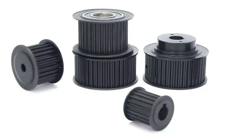
pulley

Mechanical advantage of a pulley

A pulley has a mechanical advantage over a lever because it is able to produce more force over longer distances. The mechanical advantage of a pulley sounds brilliant and could produce energy. But what exactly is this mechanical advantage? Let’s take a look. First, consider how a pulley works. A rope supports a 100kg mass, which requires 500 newtons of force to lift. If the rope supports a 100kg mass, 2 sections of rope can support that load. Using a pulley, you can lift the same weight with half the force.
A pulley’s ideal mechanical advantage is the ratio of the force applied to the total length of the rope. The larger the radius, the greater the mechanical advantage. A pulley made up of 4 rope segments has an ideal mechanical advantage of four. Therefore, a four-segment pulley would multiply the force applied by four. As the numbers on the rope segments are smaller than the total length of the rope, it would be better to use a compound pulley.
The mechanical advantage of a pulley can be calculated by using the T-method. The first step in calculating the mechanical advantage of a pulley is defining the force you need to lift. Then, divide that force by 2 to calculate the amount of force you need to lift the load. Once you know this amount, you can design a pulley to meet your needs. That way, you can achieve the perfect balance between the 2 types of pulleys.

Types of pulleys

The main function of the pulley is to change the direction of the force. The mechanical advantages of a single pulley are two. Ideally, 2 pulleys should have 2 or more mechanical advantages. The mechanical advantage of compound pulleys can be increased to 2 or more. The number of pulleys that make up the composite pulley will determine the mechanical advantage. Certain types of pulleys are combined in 1 housing.
A stepped pulley is a set of pulleys with stepped surfaces. Each face is anchored to the mid-axis in an ordered sequence. This design gives these pulleys their name. They are used to increase and decrease the speed of the driven pulley. Step pulleys are usually used in pairs. They can be straight or stepped, but usually come in pairs.
The 3 main types of pulleys are pulleys, rope pulleys, and chain pulleys. Pulley Pulley systems use mechanics to lift and lower heavy objects. The Greek historian Plutarch credits the invention of the pulley to Archimedes of ancient Sicily. The Mesopotamians used rope pulleys to lift water around 1500 BC, and Stonehenge is said to have been built using a rope pulley system.
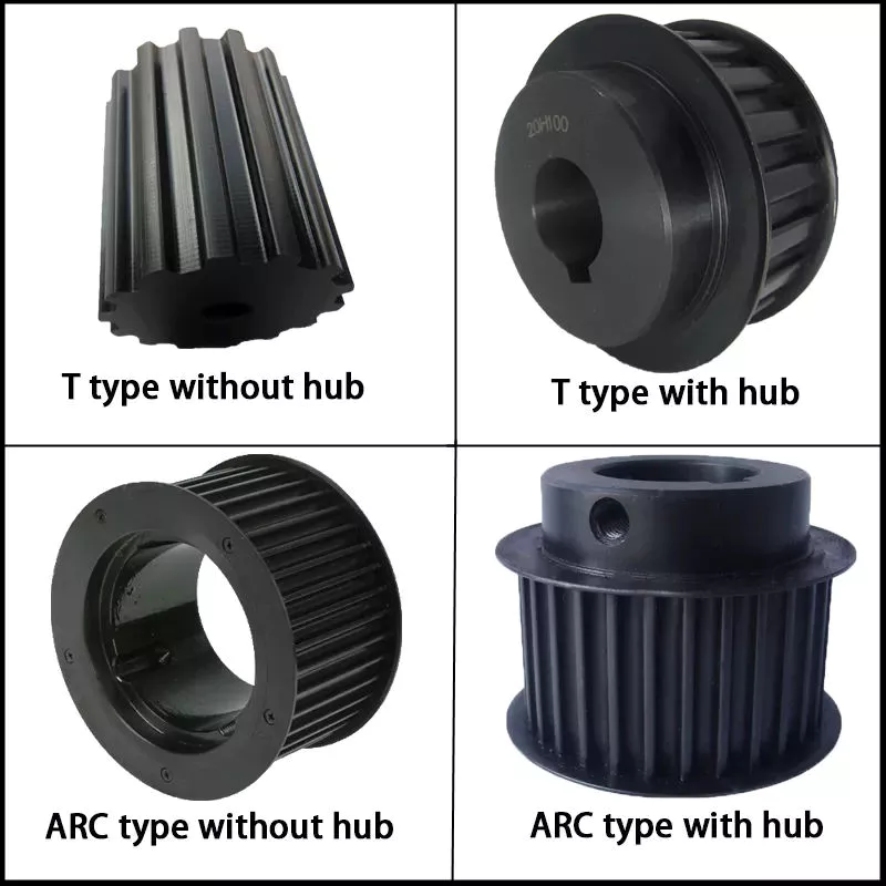
pulley

Application of pulley system

The advantages of using a pulley system are numerous. The ability to lift heavy objects is a good example. The pulley system makes it easy for people to lift blocks and other large objects. It can be used in many different applications, from utility elevators to construction cranes. In addition, it is widely used on sailing boats. If you want to learn more about the benefits of a pulley system, keep reading!
You can use the pulley system to water flowers or water plants. Some of them even lowered the pot to make cleaning easier. Pendant lights are another great place to install a pulley system. Climbing and fishing are just some of the activities that utilize the pulley. They are great for fishing and gardening. And since they are so versatile, you can use the pulley system anywhere.
To get the most out of your pulley system, you must choose a product that has all of the above attributes. A high-quality pulley must have a large pulley diameter and be made of sturdy materials. The cables must also be properly supported in the pulleys to ensure a long service life for your investment. A good cable should have minimal cracks and be lubricated. These factors are the most important considerations when choosing a pulley system for your needs.

composite pulley

Composite pulley systems combine 2 or more movable pulleys. These systems maximize the force to move the weight and can also change direction so they can be used to lift weights. Composite pulley systems can be as simple or as complex as your needs. For example, a pulley pulley system uses multiple pulleys on each axis. This method is often used for hoisting building materials.
A compound pulley system has 2 or more rope segments, each of which is pulled up on a load. It can increase lift by making objects move faster. These systems are common on large sailboats and construction sites. Composite pulleys are also available for larger boats. Due to their versatility, they are versatile tools for construction sites and large sailboats. If you have their app, you should consider buying one.
The main advantage of composite pulleys is their versatility. You can use them to lift weights or use them to save energy. Composite pulleys are especially useful for lifting heavy objects. For example, you can tie a paper clip to the end of the rope and pull it up. The flag is then lifted into the air with the help of compound pulleys. Composite pulleys are a great invention and they are often used in construction.

security considerations

There are several safety considerations to consider when using pulleys. The first is Secure Workload (SWL). This value is a general guideline for the maximum weight a pulley can safely handle. It varies according to the height and angle of the pulley. Besides SWL, there are some other factors to consider. Consider each 1 before deciding on the pulley that best suits your needs.
Another safety consideration is the weight of the load. Since the highs of the pulley are higher than the lows, it doubles in weight. The weight of the high point should not exceed 4 kN. The safety factor is calculated by multiplying the strength of the pulley by the weight of the load. Secondary COD has a safety factor of 10:1 and bulletproof primary anchors should be used with pulleys.
If using a chain hoist, you must be trained in the appropriate type of lifting. It is important not to hang on the top hooks of the structure, nor to overload or rig the hooks with multiple slings. You should also avoid corroded or damaged chains, as they can cause the crane to jam or overload. A worn chain can even cause the load to drop.
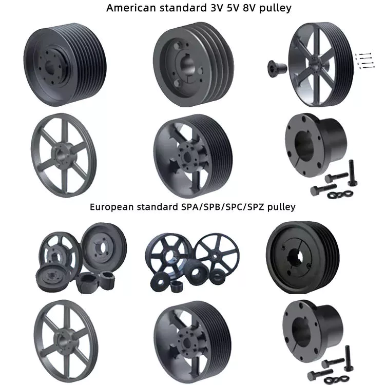
pulley

Components of a pulley system

Proper design of the pulley system can increase the life of the cables and pulleys. Larger diameter cables should be selected as they are more durable than smaller diameter cables. The cables should also be supported in the pulley grooves. The pulley must be designed to be compatible with the cable and its lubrication should be optimal. Proper lubrication of cables and pulleys will ensure maximum durability and longevity.
The first type of pulley is called a fast pulley. These pulleys are used for quick start and stop of the machine. These pulleys are usually mounted in pairs on the countershaft of the machine. One pulley is tightly mounted on the machine shaft, while the other pulley is fitted with a free-spinning mechanism. When the machine is running, the belt is mounted on the tensioner pulley, and when it is stopped, the belt slides on the independent pulley.
Composite pulley sets reduce the overall effort required by reducing the size of the pulley. These are usually attributed to Archimedes. Flat pulleys are often used in flat belt driven transmission systems. These are used in high-speed, low-power applications. Flat pulley idlers are also used on the back of traditional V-belts.

China factory Farm Machinery, Tractor Parts, OEM Casting Parts Supplier Made in China Customized Professional Foundry     wholesaler China factory Farm Machinery, Tractor Parts, OEM Casting Parts Supplier Made in China Customized Professional Foundry     wholesaler

China high quality CZPT Tractor Hydraulic Pump F0nn600bb Tractor Parts near me supplier

Product Description

FORD Tractor Hydraulic Pump F0NN6
Ford Tractor: 5610, 5640, 6610, 6640, 6810, 7610, 7740, 7840, 8240, 8340

We also support CASE IH, FIAT, FORD, JOHNDEERE, KUBOTA, MF Tractor OEM Pumps, Steering units.

1. OEM quality.
2. Advantage price.
3. Fast delivery.
4. Warranty quality.
5. Support retail and wholesale.
6. Diversified payment methods.
 

Foed Tractor OEM Paump

D0NN6

D8NN6

D8NN6

E1NN6

D0NN6

D8NN6

E6NN3K514AB, 83960261

E6NN3K514EA, 87559440

D5NN6

E6NN3K514PA

E9NN6

82988360

We insist: nobody has, we have; somebody has, we have better.
We embrace: user is priority, quality is priority, service is priority.
We expect: share the fruit of development, create brilliant career, and serve the community together.
Elephant Fluid Power Co.,Ltd Company is willing to start a new journey with you hand in hand!

We are looking for good long business partner and friendship.
If you are interested in our products, please contact me.I’ll give you a favorable quotation.


The benefits of rubber bushings and how they work

If you have experienced increased vibration while driving, you know the importance of replacing the control arm bushings. The resulting metal-to-metal contact can cause annoying driving problems and be a threat to your safety. Over time, the control arm bushings begin to wear out, a process that can be exacerbated by harsh driving conditions and environmental factors. Additionally, larger tires that are more susceptible to bushing wear are also prone to increased vibration transfer, especially for vehicles with shorter sidewalls. Additionally, these plus-sized tires, which are designed to fit on larger rims, have a higher risk of transmitting vibrations through the bushings.
bushing

rubber

Rubber bushings are rubber tubes that are glued into the inner or outer curve of a cylindrical metal part. The rubber is made of polyurethane and is usually prestressed to avoid breaking during installation. In some cases, the material is also elastic, so it can slide. These properties make rubber bushings an integral part of a vehicle’s suspension system. Here are some benefits of rubber bushings and how they work.
Rubber bushings are used to isolate and reduce vibration caused by the movement of the 2 pieces of equipment. They are usually placed between 2 pieces of machinery, such as gears or balls. By preventing vibrations, rubber bushings improve machine function and service life. In addition to improving the overall performance of the machine, the rubber bushing reduces noise and protects the operator from injury. The rubber on the shock absorber also acts as a vibration isolator. It suppresses the energy produced when the 2 parts of the machine interact. They allow a small amount of movement but minimize vibration.
Both rubber and polyurethane bushings have their advantages and disadvantages. The former is the cheapest, but not as durable as polyurethane. Compared to polyurethane, rubber bushings are a better choice for daily commutes, especially long commutes. Polyurethane bushings provide better steering control and road feel than rubber, but can be more expensive than the former. So how do you choose between polyurethane and rubber bushings?

Polyurethane

Unlike rubber, polyurethane bushings resist high stress environments and normal cycling. This makes them an excellent choice for performance builds. However, there are some disadvantages to using polyurethane bushings. Read on to learn about the advantages and disadvantages of polyurethane bushings in suspension applications. Also, see if a polyurethane bushing is suitable for your vehicle.
Choosing the right bushing for your needs depends entirely on your budget and application. Softer bushings have the lowest performance but may have the lowest NVH. Polyurethane bushings, on the other hand, may be more articulated, but less articulated. Depending on your needs, you can choose a combination of features and tradeoffs. While these are good options for everyday use, for racing and hardcore handling applications, a softer option may be a better choice.
The initial hardness of the polyurethane bushing is higher than that of the rubber bushing. The difference between the 2 materials is determined by durometer testing. Polyurethane has a higher hardness than rubber because it does not react to load in the same way. The harder the rubber, the less elastic, and the higher the tear. This makes it an excellent choice for bushings in a variety of applications.

hard

Solid bushings replace the standard bushings on the subframe, eliminating axle clutter. New bushings raise the subframe by 0.59″ (15mm), correcting the roll center. Plus, they don’t create cabin noise. So you can install these bushings even when your vehicle is lowered. But you should consider some facts when installing solid casing. Read on to learn more about these casings.
The stiffest bushing material currently available is solid aluminum. This material hardly absorbs vibrations, but it is not recommended for everyday use. Its stiffness makes it ideal for rail vehicles. The aluminum housing is prone to wear and tear and may not be suitable for street use. However, the solid aluminum bushings provide the stiffest feel and chassis feedback. However, if you want the best performance in everyday driving, you should choose a polyurethane bushing. They have lower friction properties and eliminate binding.
Sturdy subframe bushings will provide more driver feedback. Additionally, it will strengthen the rear body, eliminating any movement caused by the subframe. You can see this structural integration on the M3 and M4 models. The benefits of solid subframe bushings are numerous. They will improve rear-end handling without compromising drivability. So if you plan to install a solid subframe bushing, be sure to choose a solid bushing.
bushing

Capacitor classification

In the circuit, there is a high electric field on both sides of the capacitor grading bushing. This is due to their capacitor cores. The dielectric properties of the primary insulating layer have a great influence on the electric field distribution within the bushing. This article discusses the advantages and disadvantages of capacitor grade bushings. This article discusses the advantages and disadvantages of grading bushings for capacitors in DC power systems.
One disadvantage of capacitor grading bushings is that they are not suitable for higher voltages. Capacitor grading bushings are prone to serious heating problems. This may reduce their long-term reliability. The main disadvantage of capacitor grading bushings is that they increase the radial thermal gradient of the main insulation. This can lead to dielectric breakdown.
Capacitor grading bushing adopts cylindrical structure, which can suppress the influence of temperature on electric field distribution. This reduces the coefficient of inhomogeneity of the electric field in the confinement layer. Capacitor grading bushings have a uniform electric field distribution across their primary insulation. Capacitive graded bushings are also more reliable than nonlinear bushings.
Electric field variation is the most important cause of failure. The electrode extension layer can be patterned to control the electric field to avoid flashover or partial discharge of the primary insulating material. This design can be incorporated into capacitor grading bushings to provide better electric fields in high voltage applications. This type of bushing is suitable for a wide range of applications. This article discusses the advantages and disadvantages of capacitor grade bushings.

Metal

When choosing between plastic and metal sleeves, it is important to choose a product that can handle the required load. Plastic bushings tend to deteriorate and often crack under heavy loads, reducing their mechanical strength and service life. Metal bushings, on the other hand, conduct heat more efficiently, preventing any damage to the mating surfaces. Plastic bushings can also be made with lubricating fillers added to a resin matrix.
Plastic bushings have many advantages over metal bushings, including being cheap and versatile. Plastic bushings are now used in many industries because they are inexpensive and quick to install. These plastic products are also self-lubricating and require less maintenance than metals. They are often used in applications where maintenance costs are high or parts are difficult to access. Also, if they are prone to wear and tear, they are easy to replace.
Metal bushings can be made of PTFE, plastic or bronze and are self-lubricating. Graphite plugs are also available for some metal bushings. Their high load capacity and excellent fatigue resistance make them a popular choice for automotive applications. The bi-metallic sintered bronze layer in these products provides excellent load-carrying capacity and good friction properties. The steel backing also helps reduce processing time and avoids the need for additional pre-lubrication.
bushing

plastic

A plastic bushing is a small ball of material that is screwed onto a nut or locknut on a mechanical assembly. Plastic bushings are very durable and have a low coefficient of friction, making them a better choice for durable parts. Since they do not require lubrication, they last longer and cost less than their metal counterparts. Unlike metal bushings, plastic bushings also don’t scratch or attract dirt.
One type of acetal sleeve is called SF-2. It is made of metal alloy, cold rolled steel and bronze spherical powder. A small amount of surface plastic penetrated into the voids of the copper spherical powder. Plastic bushings are available in a variety of colors, depending on the intended application. SF-2 is available in black or grey RAL 7040. Its d1 diameter is sufficient for most applications.
Another acetal sleeve is UHMW-PE. This material is used in the production of bearings and in low load applications. This material can withstand pressures from 500 to 800 PSI and is widely available. It is also self-lubricating and readily available. Due to its high resistance to temperature and chemical agents, it is an excellent choice for low-load industrial applications. If you’re in the market for an alternative to nylon, consider acetal.
Positional tolerances in many automotive components can cause misalignment. Misaligned plastic bushings can negatively impact the driver’s experience. For example, the cross tubes used to mount the seat to the frame are made by a stamping process. The result is a misalignment that can increase torque. Also, the plastic bushing is pushed to 1 side of the shaft. The increased pressure results in higher friction, which ultimately results in a poor driving experience.
v
China high quality CZPT Tractor Hydraulic Pump F0nn600bb Tractor Parts     near me supplier China high quality CZPT Tractor Hydraulic Pump F0nn600bb Tractor Parts     near me supplier

China high quality Hydraulic Pump Re223233 Deere Tractor Parts with Free Design Custom

Product Description

Hydraulic pump RE223233 Deere Tractor Parts

Replaces Deere: RE223233
Deere : 5045D, 5045E, 5055E, 5065E, 5065M, 5075E, 5103, 5203, 5204, 5303, 5310, 5403, 5410, 5610

1. OEM quality.
2. Advantage price.
3. Fast delivery.
4. Warranty quality.
5. Support retail and wholesale.
6. Diversified payment methods.


Deere Tractor OEM Paump

RE68886 , RE57445

AZ19692,

RE223233

AR103033, AR103036

RE73947, RE72058

AL156335, AL117812

RE241577 ,RE241578

We also support CASE IH, FIAT, FORD, DEERE, KUBOTA, MF Tractor OEM Pumps, Steering units.

We insist: nobody has, we have; somebody has, we have better.
We embrace: user is priority, quality is priority, service is priority.
We expect: share the fruit of development, create brilliant career, and serve the community together.
Elephant Fluid Power Co.,Ltd Company is willing to start a new journey with you hand in hand!

We are looking for good long business partner and friendship.
If you are interested in our products, please contact me.I’ll give you a favorable quotation.


Types of pulleys and their advantages and disadvantages

There are several types of pulleys. Learn the basic equations of the pulley system. Then learn about the different uses for pulleys. The disadvantages of using pulleys will be covered. Knowing these, you can buy the pulley that suits your needs. Here are some of the best pulley types and their pros and cons.
pulley

Basic equations of pulley systems

A pulley system is a mechanism that allows 2 blocks of a certain mass to be connected by a taut rope. The acceleration of each block is the same in magnitude and direction. The external force acting on each block is the weight of the block (10g) and the tension in the string. The tension between the 2 blocks is the total tension and the force acting on the pulley is the weight of the 2 blocks.
This simple mechanism uses 2 simple equations to explain how the system works. First, the mass of the weight on both sides of the pulley must be the same. When the weight is forced to move, the rope tightens and the second pulley descends. The weight is also attached to the second pulley and must be the same distance as the first pulley. This will result in a speed ratio of 2 times the distance covered by the first pulley.
Second, we have to calculate the force required to lift the object. The lower mass is supported by a wire configuration passing through all pulleys, while the uppermost pulley is used to apply the force. The lower block is used to support the weight. The applied force needs to travel a distance nx to move the weight. This distance, called MA, can be written as:
Once we have gathered the necessary information, we can apply the calculations to the pulley system. We can also use the Mechanical Advantage Calculator to calculate the force on the anchor. To do this, we must apply a force to the load as well as to the pulley itself. Using this equation, we can calculate the force required by the load to lift the load.
pulley

Types of pulleys

There are 3 basic types of pulleys: movable, fixed and compound. Both types of pulleys translate the force applied to them. The ideal mechanical advantage of pulleys is two. This is because a single movable pulley only doubles the force, whereas a compound pulley doubles or triples the force. This type of pulley is often used with other types of pulleys.
Movable pulls move with the weight of the load, and the force pulling them increases on the lift side. They are often found in utility elevators and construction cranes. These systems are very simple, inexpensive and quiet to use. The force required to lift the object depends on the mechanical advantage of the system. The 2 most common types of pulleys are listed below. Let’s take a closer look at each one.
V-shaped pulleys are used in vehicles and electric motors. These pulleys require a “V” belt to function properly. Some have multiple “V” grooves to avoid slipping. They are used in heavy duty applications to reduce the risk of power slip. These pulleys also have more than 1 “V” groove. V-belt pulleys are commonly used in vehicles and electric motors.
Composite pulleys are made from more than 1 type of cable or rope wrapped around the wheel. They can be fixed or hinged and are usually made of stainless steel or bronze. Composite pulleys have multiple layers and can be a single unit or many different components. There are 3 main types of pulleys: fixed pulleys and composite pulleys. These are the most common types. Almost every type of pulley is used for some type of application.
Fixed pulleys have 1 advantage over movable pulleys: they change direction as the weight of the load increases. They are typically used in heavy construction equipment. Gun tackles, patio tackles, and stationary tackles are examples of equipment that use a pulley mechanism. These devices are very common and can be found on most modern construction sites. They provide great convenience for lifting large loads.

application

What are the applications of pulleys? Simply put, a pulley is a mechanical device that transforms a difficult task into an easier one. It consists of ropes and pulleys. It is usually used to lift objects. Usually, people wrap a rope around a pulley and pull up to lift the object. One disadvantage of using pulleys is that they require the same force as lifting the object directly.
One of the most popular applications of pulleys is lifting heavy objects. They help people pull up heavy objects and blocks. The system can also be used in seeders, lifts, grinders, etc. Other applications include raising flags, loading cargo, pulling curtains and rock or mountain climbing. Students can learn about the various uses of pulleys and the physics behind them.
Pulleys can be made of many different materials, depending on the application. Some are movable, which means they move with the object they are used to lift. This pulley system can be made of nylon, wire rope or fiber material. The best part about these systems is that they are easy to install and maintain. For a better grasp, use the guide or video tutorial to learn more about the pulley system and how it works.
Tapered pulleys are common in paper mills. They are high-quality pulleys that transmit power to connected parts. They can be dynamic or static and have different balances. Because pulley systems are highly customized, most industrial applications require systems designed specifically for specific applications. In this way, the system is safe, simple and inexpensive. The benefits of this design are endless.
The most common use of pulleys is for motor drives. They are used to minimize noise by applying force to the shaft to reduce the workload. They are also less expensive than gears and do not require lubrication. Furthermore, they can change the direction of the applied force. They are also less expensive than gears and are often used with other components. A screw is a cylindrical member with helical ribs used to connect something.
pulley

shortcoming

Although the pulley system makes it easier to move heavy objects, it still has some drawbacks. When using a pulley system, you must remember that the force required to lift the weight increases with the number of cycles. In addition, the distance between the puller and the heavy object increases, which may lead to accidents. Also, moving heavy objects can be tricky if the rope slips. Pulley systems are not very expensive and can be easily assembled. However, it does require a lot of space.
First, it is not efficient. Besides being inefficient, pulleys produce different forces at different speeds. Fixed pulleys use more force than the load, while movable pulleys move with the load. A movable pulley requires less force than a fixed pulley, but the combined system travels a long distance. Therefore, this method is not as efficient as the fixed method.
Pulleys are not only used in industrial processes. You can see them in various places in your daily life. For example, large construction cranes use pulleys to lift heavy loads. Even flagpoles, blinds, clotheslines, ziplines, motors and climbing equipment use pulleys. Still, despite their advantages, the disadvantages are not too serious.
Another disadvantage of the pulley is its wear and tear. While a pulley’s housing is theoretically infinite, its bearings and locking components typically wear out over time. To overcome this problem, a new bearing and locking assembly can be installed. No need to replace the housing and shaft, the entire assembly can be re-bonded and painted to replicate the original look. Alternatively, the pulley can be replaced with a new housing and shaft.
Using pulleys can also reduce the advantage of pulleys. On the other hand, interception and tackle is a system in which 2 pulleys are connected to each other using ropes. Unlike pulleys, pulley pulley systems can be adjusted in the direction of travel and can move heavy loads up to 4 times their force when used in hydraulic lifts.

China high quality Hydraulic Pump Re223233 Deere Tractor Parts     with Free Design CustomChina high quality Hydraulic Pump Re223233 Deere Tractor Parts     with Free Design Custom

China Standard Shenzhen OEM Customized CNC Aluminum Turned Forged Stamping Lathe Machined Tractor ATV/UTV Vehicle Valve Pump Trailer Hydraulic Agricultural Industrial Parts with Best Sales

Product Description

                                                                 A Letter to Our Future Partners
Dear,

Plz wait don’t scroll. No doubt, that partner is you! Thank you for visiting our Xielifeng CNC machining service at MIC now.

Xielifeng Tech is located in HangZhou, China, which focuses on CNC machining, including milling, turning, auto-lathe, die casting. Both metal and plastic material are within our capability. We provide one-stop service, from professional design analysis, to free quote, fast prototype, ISO standard manufacturing, to safe shipping and great after-sales services.

 During these years, we have win lots of trust in the global market, most of them come from North America and Europe. Now you may have steady suppliers, but still hope you can keep us in the archives to get more market news.

More interests, feel free to send us an inquiry via Contact now, or directly to our email, and then our professional sales manager will get back to you ASAP!

Warmly regards.
Peter Tu (Sales Manager)


Service Custom CNC Machining Parts of Most Materials
Quotation According to your drawing(size, material, thickness, processing content, and required technology, etc)
Tolerance & Surface Roughness +/-0.005 – 0.1mm & Ra0.2 – Ra3.2 (Customize available)
Materials Available Aluminum, Copper, Stainless steel, Iron, PE, PVC, ABS, etc.
Surface Treatment Polishing, general/hard/color oxidation, surface chamfering, tempering, etc.
Processing CNC Turning, Milling, Drilling, Auto Lathe, Tapping, Bushing, Surface Treatment, etc.
Payment method Our business face global. and support credit cards, T/T, L/C, Paypal, etc.
Drawing Formats PRO/E, Auto CAD, Solid Works , UG, CAD / CAM / CAE, PDF

FAQ: 

Q1: Where can I get product&price information?
A1: Send us an inquiry in this page or e-mail, we will contact you after upon receipt of your mail.

Q2: How soon can I get samples and how much the fee?
A2: Depending on your specific project, it usually takes 10 to 20 days. the fee depends on the product drawing, and the fee will be returned to your bulk order.

Q3: How to enjoy the OEM services?
A3: Usually, base on your design drawings or original samples, we give some technical proposals and a quotation to you, after your agreement, we produce for you.

Q4: Can you make machining parts based on our samples?
A4: Yes, we can make measurements based on your samples to make drawings for machining parts making.

Q5: Is it possible to know how are my products going on without visiting your company?
A5: We will offer a detailed production schedule and send weekly reports with digital pictures and videos which show the machining progress.

Q6: Will my drawing safe after you get it?
A6: Yes, we can sign the NDA before got your drawing.

Synthesis of Epicyclic Gear Trains for Automotive Automatic Transmissions

In this article, we will discuss the synthesis of epicyclic gear trains for automotive automatic transmissions, their applications, and cost. After you have finished reading, you may want to do some research on the technology yourself. Here are some links to further reading on this topic. They also include an application in hybrid vehicle transmissions. Let’s look at the basic concepts of epicyclic gear trains. They are highly efficient and are a promising alternative to conventional gearing systems.
Gear

Synthesis of epicyclic gear trains for automotive automatic transmissions

The main purpose of automotive automatic transmissions is to maintain engine-drive wheel balance. The kinematic structure of epicyclic gear trains (EGTs) is derived from graph representations of these gear trains. The synthesis process is based on an algorithm that generates admissible epicyclic gear trains with up to 10 links. This algorithm enables designers to design auto gear trains that have higher performance and better engine-drive wheel balance.
In this paper, we present a MATLAB optimization technique for determining the gear ratios of epicyclic transmission mechanisms. We also enumerate the number of teeth for all gears. Then, we estimate the overall velocity ratios of the obtained EGTs. Then, we analyze the feasibility of the proposed epicyclic gear trains for automotive automatic transmissions by comparing their structural characteristics.
A six-link epicyclic gear train is depicted in the following functional diagram. Each link is represented by a double-bicolor graph. The numbers on the graph represent the corresponding links. Each link has multiple joints. This makes it possible for a user to generate different configurations for each EGT. The numbers on the different graphs have different meanings, and the same applies to the double-bicolor figure.
In the next chapter of this article, we discuss the synthesis of epicyclic gear trains for automotive automatic transaxles. SAE International is an international organization of engineers and technical experts with core competencies in aerospace and automotive. Its charitable arm, the SAE Foundation, supports many programs and initiatives. These include the Collegiate Design Series and A World In Motion(r) and the SAE Foundation’s A World in Motion(r) award.
Gear

Applications

The epicyclic gear system is a type of planetary gear train. It can achieve a great speed reduction in a small space. In cars, epicyclic gear trains are often used for the automatic transmission. These gear trains are also useful in hoists and pulley blocks. They have many applications in both mechanical and electrical engineering. They can be used for high-speed transmission and require less space than other types of gear trains.
The advantages of an epicyclic gear train include its compact structure, low weight, and high power density. However, they are not without disadvantages. Gear losses in epicyclic gear trains are a result of friction between gear tooth surfaces, churning of lubricating oil, and the friction between shaft support bearings and sprockets. This loss of power is called latent power, and previous research has demonstrated that this loss is tremendous.
The epicyclic gear train is commonly used for high-speed transmissions, but it also has a small footprint and is suitable for a variety of applications. It is used as differential gears in speed frames, to drive bobbins, and for the Roper positive let-off in looms. In addition, it is easy to fabricate, making it an excellent choice for a variety of industrial settings.
Another example of an epicyclic gear train is the planetary gear train. It consists of 2 gears with a ring in the middle and the sun gear in the outer ring. Each gear is mounted so that its center rotates around the ring of the other gear. The planet gear and sun gear are designed so that their pitch circles do not slip and are in sync. The planet gear has a point on the pitch circle that traces the epicycloid curve.
This gear system also offers a lower MTTR than other types of planetary gears. The main disadvantage of these gear sets is the large number of bearings they need to run. Moreover, planetary gears are more maintenance-intensive than parallel shaft gears. This makes them more difficult to monitor and repair. The MTTR is also lower compared to parallel shaft gears. They can also be a little off on their axis, causing them to misalign or lose their efficiency.
Another example of an epicyclic gear train is the differential gear box of an automobile. These gears are used in wrist watches, lathe machines, and automotives to transmit power. In addition, they are used in many other applications, including in aircrafts. They are quiet and durable, making them an excellent choice for many applications. They are used in transmission, textile machines, and even aerospace. A pitch point is the path between 2 teeth in a gear set. The axial pitch of 1 gear can be increased by increasing its base circle.
An epicyclic gear is also known as an involute gear. The number of teeth in each gear determines its rate of rotation. A 24-tooth sun gear produces an N-tooth planet gear with a ratio of 3/2. A 24-tooth sun gear equals a -3/2 planet gear ratio. Consequently, the epicyclic gear system provides high torque for driving wheels. However, this gear train is not widely used in vehicles.
Gear

Cost

The cost of epicyclic gearing is lower when they are tooled rather than manufactured on a normal N/C milling machine. The epicyclic carriers should be manufactured in a casting and tooled using a single-purpose machine that has multiple cutters to cut the material simultaneously. This approach is widely used for industrial applications and is particularly useful in the automotive sector. The benefits of a well-made epicyclic gear transmission are numerous.
An example of this is the planetary arrangement where the planets orbit the sun while rotating on its shaft. The resulting speed of each gear depends on the number of teeth and the speed of the carrier. Epicyclic gears can be tricky to calculate relative speeds, as they must figure out the relative speed of the sun and the planet. The fixed sun is not at zero RPM at mesh, so the relative speed must be calculated.
In order to determine the mesh power transmission, epicyclic gears must be designed to be able to “float.” If the tangential load is too low, there will be less load sharing. An epicyclic gear must be able to allow “float.” It should also allow for some tangential load and pitch-line velocities. The higher these factors, the more efficient the gear set will be.
An epicyclic gear train consists of 2 or more spur gears placed circumferentially. These gears are arranged so that the planet gear rolls inside the pitch circle of the fixed outer gear ring. This curve is called a hypocycloid. An epicyclic gear train with a planet engaging a sun gear is called a planetary gear train. The sun gear is fixed, while the planet gear is driven.
An epicyclic gear train contains several meshes. Each gear has a different number of meshes, which translates into RPM. The epicyclic gear can increase the load application frequency by translating input torque into the meshes. The epicyclic gear train consists of 3 gears, the sun, planet, and ring. The sun gear is the center gear, while the planets orbit the sun. The ring gear has several teeth, which increases the gear speed.
Another type of epicyclic gear is the planetary gearbox. This gear box has multiple toothed wheels rotating around a central shaft. Its low-profile design makes it a popular choice for space-constrained applications. This gearbox type is used in automatic transmissions. In addition, it is used for many industrial uses involving electric gear motors. The type of gearbox you use will depend on the speed and torque of the input and output shafts.

China Standard Shenzhen OEM Customized CNC Aluminum Turned Forged Stamping Lathe Machined Tractor ATV/UTV Vehicle Valve Pump Trailer Hydraulic Agricultural Industrial Parts     with Best SalesChina Standard Shenzhen OEM Customized CNC Aluminum Turned Forged Stamping Lathe Machined Tractor ATV/UTV Vehicle Valve Pump Trailer Hydraulic Agricultural Industrial Parts     with Best Sales

China Standard Custom Manufacturing Galvanized Sheet Metal Fabrication Laser Cutting Stamping Steel Parts Used for Tractor with Great quality

Product Description

Surface treatment for CNC Machining part:  

1 Zinc/nickel/chrome plating
2 hot galvanized
3 painting
4 powder coating
5 Anodize Oxidation, or with colors: like silver, blue, red, etc. 
6  plating, silver-plated, Gold-plated, etc
7 polishing
8 electrolytic polishing
9 sank without electricity nickel
etc etc.    


One-stop Solution

From mold design, mold making, machining, fabrication, welding, surface treatment, assembly, packing to shipping

Quality Guarantee

We have a professional team to control the quality. Experienced engineers, precision machines, CMM and QC system

Customer Service

Every client is served by a specialized sales for timely technical support and after-sales service


ISO registered company, we specialized in CNC Machining and focusing on superior workmanship, absolute quality, cleanliness, and lead time. We’re a firmly united team of talented and experienced engineers, machinists and technical consultants, who commit to helping solve problems relative to manufacturing precision and complex machined parts, including design, product costing, quality, assembly service, etc.

Workshop equipment

Certifications


Packaging & Shipping

FAQ

Q1: Are you a factory or a trading company?

 A1: We are a professional manufacturer of CNC parts for over 14 years.
 
Q2: How can I get quotation?
 A2: Please help to send drawing (2D and 3D drawing) to us, so we can know the raw material, size and surface treatment, tolerance and other details of the product. And also inform us the quantity you need.
 
Q3: What kind of material you can process?
A3: Normally Aluminum alloy and stainless steel, but we also can do titanium alloy steel, copper alloy steel special alloy steel and non-metal material.
 
Q4: What is the minimum size tolerance you can do?
A4: The minimum size tolerance we can do is 0.001mm.
 
Q5: What is the biggest range you can do?
A5: The biggest range we can do is 1500mm.
 
Q6: Can you do precise and complicated CNC parts?
A6: Yes, we can do precise and complicated CNC parts by our 5/4/3 axis CNC machines
 
Q7: Can you accept sample order?
A7: Yes, we can do sample order per your requirement.
 
Q8:Can you accept custom packing?
A8: Yes, we can do custom packing as your requirement.

How to Determine the Quality of a Worm Shaft

There are many advantages of a worm shaft. It is easier to manufacture, as it does not require manual straightening. Among these benefits are ease of maintenance, reduced cost, and ease of installation. In addition, this type of shaft is much less prone to damage due to manual straightening. This article will discuss the different factors that determine the quality of a worm shaft. It also discusses the Dedendum, Root diameter, and Wear load capacity.
worm shaft

Root diameter

There are various options when choosing worm gearing. The selection depends on the transmission used and production possibilities. The basic profile parameters of worm gearing are described in the professional and firm literature and are used in geometry calculations. The selected variant is then transferred to the main calculation. However, you must take into account the strength parameters and the gear ratios for the calculation to be accurate. Here are some tips to choose the right worm gearing.
The root diameter of a worm gear is measured from the center of its pitch. Its pitch diameter is a standardized value that is determined from its pressure angle at the point of zero gearing correction. The worm gear pitch diameter is calculated by adding the worm’s dimension to the nominal center distance. When defining the worm gear pitch, you have to keep in mind that the root diameter of the worm shaft must be smaller than the pitch diameter.
Worm gearing requires teeth to evenly distribute the wear. For this, the tooth side of the worm must be convex in the normal and centre-line sections. The shape of the teeth, referred to as the evolvent profile, resembles a helical gear. Usually, the root diameter of a worm gear is more than a quarter inch. However, a half-inch difference is acceptable.
Another way to calculate the gearing efficiency of a worm shaft is by looking at the worm’s sacrificial wheel. A sacrificial wheel is softer than the worm, so most wear and tear will occur on the wheel. Oil analysis reports of worm gearing units almost always show a high copper and iron ratio, suggesting that the worm’s gearing is ineffective.

Dedendum

The dedendum of a worm shaft refers to the radial length of its tooth. The pitch diameter and the minor diameter determine the dedendum. In an imperial system, the pitch diameter is referred to as the diametral pitch. Other parameters include the face width and fillet radius. Face width describes the width of the gear wheel without hub projections. Fillet radius measures the radius on the tip of the cutter and forms a trochoidal curve.
The diameter of a hub is measured at its outer diameter, and its projection is the distance the hub extends beyond the gear face. There are 2 types of addendum teeth, 1 with short-addendum teeth and the other with long-addendum teeth. The gears themselves have a keyway (a groove machined into the shaft and bore). A key is fitted into the keyway, which fits into the shaft.
Worm gears transmit motion from 2 shafts that are not parallel, and have a line-toothed design. The pitch circle has 2 or more arcs, and the worm and sprocket are supported by anti-friction roller bearings. Worm gears have high friction and wear on the tooth teeth and restraining surfaces. If you’d like to know more about worm gears, take a look at the definitions below.
worm shaft

CZPT’s whirling process

Whirling process is a modern manufacturing method that is replacing thread milling and hobbing processes. It has been able to reduce manufacturing costs and lead times while producing precision gear worms. In addition, it has reduced the need for thread grinding and surface roughness. It also reduces thread rolling. Here’s more on how CZPT whirling process works.
The whirling process on the worm shaft can be used for producing a variety of screw types and worms. They can produce screw shafts with outer diameters of up to 2.5 inches. Unlike other whirling processes, the worm shaft is sacrificial, and the process does not require machining. A vortex tube is used to deliver chilled compressed air to the cutting point. If needed, oil is also added to the mix.
Another method for hardening a worm shaft is called induction hardening. The process is a high-frequency electrical process that induces eddy currents in metallic objects. The higher the frequency, the more surface heat it generates. With induction heating, you can program the heating process to harden only specific areas of the worm shaft. The length of the worm shaft is usually shortened.
Worm gears offer numerous advantages over standard gear sets. If used correctly, they are reliable and highly efficient. By following proper setup guidelines and lubrication guidelines, worm gears can deliver the same reliable service as any other type of gear set. The article by Ray Thibault, a mechanical engineer at the University of Virginia, is an excellent guide to lubrication on worm gears.

Wear load capacity

The wear load capacity of a worm shaft is a key parameter when determining the efficiency of a gearbox. Worms can be made with different gear ratios, and the design of the worm shaft should reflect this. To determine the wear load capacity of a worm, you can check its geometry. Worms are usually made with teeth ranging from 1 to 4 and up to twelve. Choosing the right number of teeth depends on several factors, including the optimisation requirements, such as efficiency, weight, and centre-line distance.
Worm gear tooth forces increase with increased power density, causing the worm shaft to deflect more. This reduces its wear load capacity, lowers efficiency, and increases NVH behavior. Advances in lubricants and bronze materials, combined with better manufacturing quality, have enabled the continuous increase in power density. Those 3 factors combined will determine the wear load capacity of your worm gear. It is critical to consider all 3 factors before choosing the right gear tooth profile.
The minimum number of gear teeth in a gear depends on the pressure angle at zero gearing correction. The worm diameter d1 is arbitrary and depends on a known module value, mx or mn. Worms and gears with different ratios can be interchanged. An involute helicoid ensures proper contact and shape, and provides higher accuracy and life. The involute helicoid worm is also a key component of a gear.
Worm gears are a form of ancient gear. A cylindrical worm engages with a toothed wheel to reduce rotational speed. Worm gears are also used as prime movers. If you’re looking for a gearbox, it may be a good option. If you’re considering a worm gear, be sure to check its load capacity and lubrication requirements.
worm shaft

NVH behavior

The NVH behavior of a worm shaft is determined using the finite element method. The simulation parameters are defined using the finite element method and experimental worm shafts are compared to the simulation results. The results show that a large deviation exists between the simulated and experimental values. In addition, the bending stiffness of the worm shaft is highly dependent on the geometry of the worm gear toothings. Hence, an adequate design for a worm gear toothing can help reduce the NVH (noise-vibration) behavior of the worm shaft.
To calculate the worm shaft’s NVH behavior, the main axes of moment of inertia are the diameter of the worm and the number of threads. This will influence the angle between the worm teeth and the effective distance of each tooth. The distance between the main axes of the worm shaft and the worm gear is the analytical equivalent bending diameter. The diameter of the worm gear is referred to as its effective diameter.
The increased power density of a worm gear results in increased forces acting on the corresponding worm gear tooth. This leads to a corresponding increase in deflection of the worm gear, which negatively affects its efficiency and wear load capacity. In addition, the increasing power density requires improved manufacturing quality. The continuous advancement in bronze materials and lubricants has also facilitated the continued increase in power density.
The toothing of the worm gears determines the worm shaft deflection. The bending stiffness of the worm gear toothing is also calculated by using a tooth-dependent bending stiffness. The deflection is then converted into a stiffness value by using the stiffness of the individual sections of the worm shaft. As shown in figure 5, a transverse section of a two-threaded worm is shown in the figure.

China Standard Custom Manufacturing Galvanized Sheet Metal Fabrication Laser Cutting Stamping Steel Parts Used for Tractor     with Great qualityChina Standard Custom Manufacturing Galvanized Sheet Metal Fabrication Laser Cutting Stamping Steel Parts Used for Tractor     with Great quality

China Standard Gearless Tractor Asia CZPT Parts for Elevator Funicular Car with Best Sales

Product Description

Asia CZPT Passenger Parts for Elevator 
Company Profile
Asia CZPT elevator Co., Ltd. is a professional elevator manufacturer integrating R&D,design,production,sales,installation and maintenance.Its main products include passenger elevator,cargo elevator,sightseeing elevator,sickbed elevator,villa elevator,car elevator,escalator,automatic pedestrian way,sundry elevator,three-dimentional garage and other products.

Factory Show

Product Description
Asia CZPT Elevator adopts 32-bit parallel central processing unit for high-speed processing. The most advanced double closed-loop system of Asian CZPT Elevator ensures high-precision and fast response control in the range of the highest speed and the lowest speed. 

 Asia CZPT Elevator  uses the latest permanent magnet gearless to replace the traditional worm and worm traction machine, realizing the super miniaturization of the traction machine, thin, light weight, small volume, eliminating the mechanical loss between the gears, saving more than 60% energy .

Q&A
Q: Why do you choose Asia CZPT Elevator?
1. “One-stop” service mode
2. high-quality elevator products
3. Perfect installation and after-sales service
Q: What advantages do you have?
1.Safety&Reliability Asia CZPT elevator put passengers safety at first,the elevator networking is incorporated into the Internet platform,all information of the elevator can be querried,maintained and managed.
2.Cost Reduction At present, most elevator manufacturers are generally uses the braking energy, the energy consumption on the resistance, CZPT elevator drive system adopts regenerative braking units, the elevator can run in 4 quadrant of the energy feedback to the power grid so brings 50% energy-saving than ordinary AC elevator,20% than the ordinary elevator, greatly reduces the operating costs of the lift.
3.Environmental-Friendly CZPT elevator  uses the latest permanent magnet gearless to
replace the traditional turbo worm tractor, realizing the miniaturization of the tractor, light weight, small size, eliminating the mechanical consumption between the gears, and achieving the environmental requirements of no oil, no maintenance, minimum noise, minimum engine room.
4.High Technology CZPT elevator adopts VVVF technology,and also uses IGBT,which is the most advanced transistor in the world,the noise of the motor is greatly reduced and the service life of the motor is prolonged.


Ball Screws – Dimensions, Applications, and Benefits

Ball screws are popular, lightweight, precision mechanical components. They are commonly used in machinery, gears, and knurled objects. These screw-like parts can be easily maintained and lubricated using oil. This article discusses their dimensions, applications, and benefits. The following sections provide additional information to help you select the right ball screw for your needs. We’ll discuss some of the important characteristics of ball screws and what makes them so useful.
air-compressor

Preloading

A key problem with nut-to-ball screw backlash is the ability of the nut to move freely on the threads of the ball screw. To solve this problem, a patented solution was developed. The patent, 4,557,156, describes an innovative method for preloading ball screws and nuts. By applying a preloading nut, the threads of the ball screw are prevented from moving back and forth with the nut.
A mechanical design that involves axial play involves a lot of mass, inertia, and complexity. These characteristics lead to wear and rust problems. Preloading ball screws using a dynamic system reduces mechanical complexity by allowing preload to be adjusted while the mechanism is running. This also reduces the number of mechanical parts and simplifies manufacturing. Thus, the preloading method of the present invention is advantageous.
The servo motors used in the system monitor the output torque and adjust the power to 1 motor in a dynamic way, thus creating a torque differential between the balls. This torque differential in turn creates a preload force between the ball nuts. The servo motors’ output torque is controlled in this manner, and the machine’s backlash clearance can be precisely controlled. Hence, the machine can perform multiple tasks with increased precision.
Several prior art methods for preloading ball screws are described in detail in FIG. 3. The helical thread grooves of the ball screw 26 and the nut 24 define a pathway for roller balls to travel along. The stylized broken line indicates the general position of the axis of the ball roller screw 26. The corresponding ball screws are used in a number of applications. This technique may be used to manufacture custom-sized screws.

Lubrication

Ball screws are mechanical elements that roll balls through a groove. Improper lubrication can reduce the life of these screw elements. Improper lubrication can lead to shaft damage, malfunction, and decreased performance. This article discusses the importance of proper lubrication and how to do it. You can learn how to properly lubricate ball screws in the following paragraphs. Here are some tips to ensure long-term performance and safety of ball screws.
The first thing you should do is determine the type of lubricant you’ll be using. Oils are preferred because they tend to remain inside the ball nut, and grease can build up in it. Oils also tend to have better anti-corrosion properties than grease. However, grease is more likely to be clogged with debris than oils. So, before you choose the lubricant that’s right for your screw, make sure you wash it off.
The oil used in ball screw lubrication must be applied at a controlled rate. It can prevent metal-on-metal contact and clean out contaminants as it passes through the ball nut. However, oil as a lubricant is expensive and can contaminate the process if it mixes with the cutting fluid. Grease, on the other hand, is inexpensive, requires fewer applications, and does not contaminate process fluids.
If you use a synthetic oil for lubrication, make sure to choose a viscosity that is appropriate for the operating temperature. Oil viscosity can increase the temperature of the ball screw assembly, and excessive oil can reduce its life. A correct amount of oil will reduce the temperature of the ball screw assembly, while too little will increase friction and wear. Use the following guidelines to determine the right amount of oil for your screw.
air-compressor

Dimensions

Dimensions of ball screws are a very important aspect to consider when determining the best type for your application. Technical acceptance conditions for ball screws specify the allowed deviations during acceptance tests. The tolerance class can also change, depending on the needs of a specific application. The following table lists the most important tolerance values for the full range of screw lengths. This table is a helpful guide when looking for a specific screw. The table below lists the dimensions of common ball screws.
The axial load applied to a ball screw is 0.5 x Fpr / 2Fpr. The minimum screw diameter is known as the root diameter. The axial load causes the screw shaft to deform in a certain way (DL1 and DL2). The elastic deflection induced by the load on a ball screw is called its rigidity. This rigidity is important for calculating sizing parameters for a ball screw.
The preload value of the ball screw affects the dynamic load capacity. A preload of 10 percent is considered adequate, while a value greater than this may compromise the screw’s durability. In general, a high preload value will result in a lower dynamic load capacity and greater wear. However, the preload value must be calculated with the relevant screw parameters. This is because a high preload value reduces the screw’s durability.
To ensure that your screw meets the specified parameters, the dynamic load capacity must be calculated. This is the amount of force a ball screw will withstand under a specified load. This calculation also includes strength checks. If you are using a ball screw for applications that need extra strength, it may require a safety factor. For example, if the screw is used for double-axial mounting, then the outer ball nut must be inserted into the nut, causing a secondary load.

Applications

The present invention provides a simple, yet highly effective way to mount a ball screw. Its absence of insert slots or through holes makes it simpler to assemble and provides a more uniform nut. The lack of mechanical features also reduces heat treatment issues, and the nut’s hardness can be uniformly hardened. As a result, the screw’s overall performance is improved. Here are some examples of applications for ball screws.
Preloading is the process of applying force to a ball screw. This increases the rigidity of the screw assembly and eliminates backlash, which is lost motion caused by clearance between the nut and ball. Backlash disrupts repeatability and accuracy. Spacer preloading involves inserting force between 2 ball nuts and transmitting it through the grooves. This method is ideal when preloading is needed in large quantities. In addition to increasing rigidity, preloading can improve accuracy.
Ball screws require careful care in their working surfaces to prevent contamination. Rubber or leather bellows can be used to protect their surfaces, while positive air pressure can be applied to the screw. Preloading eliminates backlash, a common problem among screw assemblies. In addition to the numerous applications for ball screws, they are also critical to computer-controlled motion-control systems and wire bonding. And there are many more examples. So what are the benefits of using these devices?
The spring preloading system uses a spring in between 2 ball nuts, applying tensional forces to the ball nuts. This spring creates grooves in the nut’s middle, which facilitates recirculation of the balls. The spring preloading mechanism is more compact than the double nut mechanism, but the lengthening of the lead reduces the ball screw’s load capacity. Its compact design makes it ideal for small clearance assemblies.
air-compressor

Maintenance

In addition to performing maintenance tasks yourself, the manufacturer of ball screws should offer reverse engineering services that will enable them to identify specific problems. The process of reverse engineering allows ball screw manufacturers to develop new ball screws and parts. In the event that a ball screw is beyond repair, a manufacturer can often save a significant amount of money by repairing it instead of replacing it. In addition to repairing a ball screw, the manufacturer should also offer free evaluation services for the component. Reconditioning and replacement involve the use of new parts, while reloading and replacement replace the screw.
Performing routine maintenance checks on ball screw assemblies is essential for maintaining optimal performance and extending their service life. Overtime, excessive wear can lead to a variety of problems, including backlash, vibration, and ball bearing noise. In addition, the increased friction increases the required torque for turning a screw, causing system failure and significant downtime. To ensure that a ball screw is fully functional, it must be checked for wear and maintain the proper lubrication system.
Discoloration or pitting on a ball screw indicates that it is in need of repair. The same is true if there are chatter marks in the ball groove. Oftentimes, a ball screw needs a new lubrication seal or wipers. Additionally, it may be missing or over-wearing, which could result in permanent failure. Finally, excessive power draw could be a sign of improper lubrication or improper installation.
Proper maintenance is essential for any machine tool. When performed properly, machine tools can last decades with continuous use. Proper care and maintenance is essential to ensure long life and optimal performance. In addition to improving machine tool uptime, proper maintenance affects the accuracy and repeatability of the end product. Therefore, premium machine tool manufacturers focus on the performance and durability of ball screws. They develop innovative designs and lubricants to optimize the lifespan of their products.

China Standard Gearless Tractor Asia CZPT Parts for Elevator Funicular Car     with Best SalesChina Standard Gearless Tractor Asia CZPT Parts for Elevator Funicular Car     with Best Sales

China OEM Aluminum Part Car Brake Shoe Machine Tractor CZPT Joint Machining Parts Hot Sale near me manufacturer

Product Description

HangZhou CZPT Hardware Machinery Co., Ltd. mainly provides intelligent manufacturing solutions for precision hardware parts for domestic and foreign customers. The company was established in 2008 and currently has more than 60 sets of various high-precision cutting-edge equipment and more than 80 employees in the production system, including There are more than 40 senior technical talents, and a talent directional transfer plan has been signed with a number of technical schools and training centers.
 
The company’s business involves precision parts and hardware processing in many industries such as auto parts, 3C automation equipment, aerospace, construction machinery, medical, food, new energy battery equipment, instrumentation, precision instruments, hardware tools, etc. At the same time, it also provides customers with precision parts. Design and manufacture of fixtures, jigs, mold accessories, processing of special material parts (such as ceramics, cemented carbide) and automation equipment design, installation, debugging, and production equipment maintenance, improvement and other related businesses.

In terms of production, according to the ISO9001:2015 quality management system, we strictly control each link of product production to ensure product performance and quality. At the same time, the company has also established a systematic, scientific and effective international information security management system, from professional And authoritative level to provide customers with information security, so that customers’ products will not have security risks of leakage, so that the delivery cycle is guaranteed.

The company adheres to the corporate tenet of “emphasis on quality, integrity, and responsibility”, with the business philosophy of “customer first, technology, efficiency, and service”. Under the guidance of the “Four Fines” business policy, the company has reached the forefront of the industry in the entire precision parts processing industry.

At present, the company has served nearly 100 customers, 80% of which are well-known enterprises in the industry. At the same time, we have a perfect after-sales service system in the industry, and continue to use a solid technical foundation and strict scientific management system to continuously improve and surpass Customer satisfaction, so that customers feel comfortable before cooperation and rest assured after cooperation.

Our advantage of cnc machining:

Business Type

Manufacturer


Advantage

1. Qida is factory providing CNC machining service for more than 10years, we focus on client’s demand and client’s satisfaction.

2. Provide 2D & 3D drawing for modifying

3. Competitive price with good quality

4. Small order is acceptable

5. Short delivery time (7-25days according to order Qty)

6. Customized size and specification /OEM available

7. Near HangZhou and HangZhou, convenient transportation


Application

.Automobile, motorcycle, medical machinery, electronics, fixtures, automation, etc

Materials Available of CNC Machining:


Materials Available


Stainless Steel

SS201, SS303, SS304, SS316 etc.

Steel

Q235, 20#, 45# etc.cr12mor, 


Brass

C36000 ( C26800), C37700 ( HPb59), C38500( HPb58), C27200(CuZn37) , C28000(CuZn40)

Iron:

1213, 12L14,1215 etc.

Bronze

C51000, C52100, C54400, etc.

Aluminum

Al6061, Al6063,AL7075,AL5052 etc

Better services of CNC machining:

(Payment Terms/Trade Term/Shipment Terms/ ):

Our Processing

CNC machining, CNC milling and turning, drilling, grinding, bending, stamping, tapping, injection
Wire cut

Surface finish

Zinc-plated, nickel-plated, chrome-plated, silver-plated, gold-plated, imitation gold-plated,

Tolerance

0.05mm~0.1mm

QC System

100% inspection before shipment

Drawing format

CAD / PDF/ DWG/ IGS/ STEP

Packaging

Standard package / Carton or Pallet / As per customized specifications

Payment Terms

30 -50%T/T in advance, 70-50% balance before delivery; Pay Pal or Western Union is acceptable.

Trade terms

EXW, FOB, CIF, As per customer’s request


Shipment Terms

1) 0-100kg: express & air freight priority

2) >100kg: sea freight priority

3) As per customized specifications


Note

All cnc machining parts are custom made according to customer’s drawings or samples, no stock.

If you have any cnc machining parts to be made, please feel free to send your kind drawings/samples to us

FAQ:
What is your product range?
1.CNC machining parts, precision parts, CNC parts, metal machining parts.
2.CNC turning parts, CNC turned parts,Lathe parts, turned parts.
3.CNC milling parts, CNC milled parts, metal milling parts.
4.CNC machined parts,CNC machine part, CNC machinery parts.
5.Metal parts, Auto parts, mechanical parts.spare parts,accessories,hardware.
6.Die casting parts,aluminum casting parts, Zinc casting parts.
7.Die stamping parts, metal stamping parts, press stamping tooling
8. Sheet metal fabrication, bending parts, laser cutting parts, welding parts.
 
Are you a manufacturer?
Yes, We are the manufacturer of all kinds of metal parts by CNC machining, turning, milling, stamping,
casting and bending with13 years’experince ,Warmly welcome to visit our factory at any time.
 
What is material you can process?
Stainless steel: SUS303, SUS304, SUS316, SUS316L, SUS430, SUS440, etc
Aluminum: 6061-T6, 6063-T5, 7075-T6, 2011, 2017, 2571, 5052, 5083, 6082 etc
Brass/copper: C11000, C15710, C12000, C26000, C36000, etc
Carbon steel:  Q235,S235JR,1571, 1015, 1571, 1571, 1030, 1035, 1040, 1045, etc
Plastic: PVC, POM, Telfon, Delrin, PEEK ,Nylon, ABS, PC, PP,PA6, PA66, etc
Free cutting steel: 1211, 12L13, 12L14, 1215, etc
Tool Steel: SKD61,SKD11,HSS M2,ASP23 ,H13,1.2344,D2,1.2379,etc
Alloy steel: 40Cr,15CrMo,4140,4340,35CrMo,16MnCr5
Titanium alloy
 
What benefit we can get from you?
1)Competitive price
2)High quality control : 100% full inspection before shipment
3)High precision, tolerance can be ± 0.005mm
4)Fast lead time (5-7days for samples, 12-15 days for mass production)
5)Non-standard//OEM//customized service provided
6)No MOQ, small QTY is acceptable.
7)ISO 9001:2015 certificated factory, ROHS material used
9)Professional export packing: separate Blister plastic box or Bubble Wrap/Pearl Wool +Carton+Wooded Case, keep no scratch and damage
 
How does the CZPT control the quality?
1)During processing, the operating machine worker inspect the each sizes by themselves.
2)After finished the first whole part, will show to QA for full inspection.
3)Before shipment, the QA will inspect according to ISO sampling inspection standard for mass production. Will do 100% full checking for small QTY.
4) when shipping the goods, we will attached the inspection report with the parts.
 
How to handle the complains?
1)During processing, if found any sizes defective, we will inform the clients and get clients approval.
2)If happen any complaints after got the goods, pls show us photos and detail complaints points, we will check with the production department and QC depart. Immediately and give solving solution with 6 hours.
3)If need re-make, we will arrange re-make urgently and ship you new replacement within 5 days. CZPT will bear all the cost ( include shipping cost).
 
What’s the payment term?
50% deposit, 50% balance by T/T before shipment when order amount over 5000USD.
100% T/T in advance when amount less than 5000USD
L/C payment term for big amount order is acceptable.
Paypal and Western Union for samples cost or very small order.
 
 
What’s the delivery time ?
Normal for samples, 5-7 working days;
For mass production, it takes about 12-15 working days.
If any urgent parts, we can provide preferential processing and control the delivery time as you required.
 
What is the standard of package?
Professional export packing:
1)Separate Blister plastic box or Bubble Wrap/Pearl Wool, keep no scratch and damage.
2)Under 100 KGS parts, use strong DHL export Carton .
3)Above 100 KGS, will customize Wooded case for packing.
 
How to ship the parts?
1)Normally, we shipped the goods by DHL,FEDEX,UPS,TNT express.
2-3 days can arrived the clients’ company directly.
2)For heavy parts, can shipped by air or by sea according to customers’indication.
 
Can we get some sample?
1.Free sample can be provided,but the clients will bear the shipping cost.
2.Samplemaking can be satisfied as customer’s demands,and the sample cost is about 50-100 USD for each part,it depends on the processing.
3. Sample charge is returnable after order the mass production.
 
What kind of certificate you have ?
We have ISO9001:2015
RoHS compliance for material and surface treatment
 
What information should i let you know once i want to make a inquiry?
1.The drawings ( PDF,CAD or 3D )?
2. The material for each drawings?
3. The surface treatment requirement.
4. How many pieces do you need?
 
How fast you can get quotation from CZPT ?
After get customer’s detail enquiry( Clear drawings, material, QTY, surface treatment).
Normally, we will provide offer within 6 hours.
If more than 100 drawings, will provide price within 24 hours.
 
What is your main market?
North America, South America, Western European,
Southeast Asia,Australia
 

Guide to Drive Shafts and U-Joints

If you’re concerned about the performance of your car’s driveshaft, you’re not alone. Many car owners are unaware of the warning signs of a failed driveshaft, but knowing what to look for can help you avoid costly repairs. Here is a brief guide on drive shafts, U-joints and maintenance intervals. Listed below are key points to consider before replacing a vehicle driveshaft.
air-compressor

Symptoms of Driveshaft Failure

Identifying a faulty driveshaft is easy if you’ve ever heard a strange noise from under your car. These sounds are caused by worn U-joints and bearings supporting the drive shaft. When they fail, the drive shafts stop rotating properly, creating a clanking or squeaking sound. When this happens, you may hear noise from the side of the steering wheel or floor.
In addition to noise, a faulty driveshaft can cause your car to swerve in tight corners. It can also lead to suspended bindings that limit overall control. Therefore, you should have these symptoms checked by a mechanic as soon as you notice them. If you notice any of the symptoms above, your next step should be to tow your vehicle to a mechanic. To avoid extra trouble, make sure you’ve taken precautions by checking your car’s oil level.
In addition to these symptoms, you should also look for any noise from the drive shaft. The first thing to look for is the squeak. This was caused by severe damage to the U-joint attached to the drive shaft. In addition to noise, you should also look for rust on the bearing cap seals. In extreme cases, your car can even shudder when accelerating.
Vibration while driving can be an early warning sign of a driveshaft failure. Vibration can be due to worn bushings, stuck sliding yokes, or even springs or bent yokes. Excessive torque can be caused by a worn center bearing or a damaged U-joint. The vehicle may make unusual noises in the chassis system.
If you notice these signs, it’s time to take your car to a mechanic. You should check regularly, especially heavy vehicles. If you’re not sure what’s causing the noise, check your car’s transmission, engine, and rear differential. If you suspect that a driveshaft needs to be replaced, a certified mechanic can replace the driveshaft in your car.
air-compressor

Drive shaft type

Driveshafts are used in many different types of vehicles. These include four-wheel drive, front-engine rear-wheel drive, motorcycles and boats. Each type of drive shaft has its own purpose. Below is an overview of the 3 most common types of drive shafts:
The driveshaft is a circular, elongated shaft that transmits torque from the engine to the wheels. Drive shafts often contain many joints to compensate for changes in length or angle. Some drive shafts also include connecting shafts and internal constant velocity joints. Some also include torsional dampers, spline joints, and even prismatic joints. The most important thing about the driveshaft is that it plays a vital role in transmitting torque from the engine to the wheels.
The drive shaft needs to be both light and strong to move torque. While steel is the most commonly used material for automotive driveshafts, other materials such as aluminum, composites, and carbon fiber are also commonly used. It all depends on the purpose and size of the vehicle. Precision Manufacturing is a good source for OEM products and OEM driveshafts. So when you’re looking for a new driveshaft, keep these factors in mind when buying.
Cardan joints are another common drive shaft. A universal joint, also known as a U-joint, is a flexible coupling that allows 1 shaft to drive the other at an angle. This type of drive shaft allows power to be transmitted while the angle of the other shaft is constantly changing. While a gimbal is a good option, it’s not a perfect solution for all applications.
CZPT, Inc. has state-of-the-art machinery to service all types of drive shafts, from small cars to race cars. They serve a variety of needs, including racing, industry and agriculture. Whether you need a new drive shaft or a simple adjustment, the staff at CZPT can meet all your needs. You’ll be back on the road soon!

U-joint

If your car yoke or u-joint shows signs of wear, it’s time to replace them. The easiest way to replace them is to follow the steps below. Use a large flathead screwdriver to test. If you feel any movement, the U-joint is faulty. Also, inspect the bearing caps for damage or rust. If you can’t find the u-joint wrench, try checking with a flashlight.
When inspecting U-joints, make sure they are properly lubricated and lubricated. If the joint is dry or poorly lubricated, it can quickly fail and cause your car to squeak while driving. Another sign that a joint is about to fail is a sudden, excessive whine. Check your u-joints every year or so to make sure they are in proper working order.
Whether your u-joint is sealed or lubricated will depend on the make and model of your vehicle. When your vehicle is off-road, you need to install lubricable U-joints for durability and longevity. A new driveshaft or derailleur will cost more than a U-joint. Also, if you don’t have a good understanding of how to replace them, you may need to do some transmission work on your vehicle.
When replacing the U-joint on the drive shaft, be sure to choose an OEM replacement whenever possible. While you can easily repair or replace the original head, if the u-joint is not lubricated, you may need to replace it. A damaged gimbal joint can cause problems with your car’s transmission or other critical components. Replacing your car’s U-joint early can ensure its long-term performance.
Another option is to use 2 CV joints on the drive shaft. Using multiple CV joints on the drive shaft helps you in situations where alignment is difficult or operating angles do not match. This type of driveshaft joint is more expensive and complex than a U-joint. The disadvantages of using multiple CV joints are additional length, weight, and reduced operating angle. There are many reasons to use a U-joint on a drive shaft.
air-compressor

maintenance interval

Checking U-joints and slip joints is a critical part of routine maintenance. Most vehicles are equipped with lube fittings on the driveshaft slip joint, which should be checked and lubricated at every oil change. CZPT technicians are well-versed in axles and can easily identify a bad U-joint based on the sound of acceleration or shifting. If not repaired properly, the drive shaft can fall off, requiring expensive repairs.
Oil filters and oil changes are other parts of a vehicle’s mechanical system. To prevent rust, the oil in these parts must be replaced. The same goes for transmission. Your vehicle’s driveshaft should be inspected at least every 60,000 miles. The vehicle’s transmission and clutch should also be checked for wear. Other components that should be checked include PCV valves, oil lines and connections, spark plugs, tire bearings, steering gearboxes and brakes.
If your vehicle has a manual transmission, it is best to have it serviced by CZPT’s East Lexington experts. These services should be performed every 2 to 4 years or every 24,000 miles. For best results, refer to the owner’s manual for recommended maintenance intervals. CZPT technicians are experienced in axles and differentials. Regular maintenance of your drivetrain will keep it in good working order.

China OEM Aluminum Part Car Brake Shoe Machine Tractor CZPT Joint Machining Parts Hot Sale     near me manufacturer China OEM Aluminum Part Car Brake Shoe Machine Tractor CZPT Joint Machining Parts Hot Sale     near me manufacturer

China Hot selling ODM CMC Machinig Aluminum Part Tractor CZPT Joint Lianhuashan Firecrackers Car Parts with high quality

Product Description

HangZhou CZPT hardware machinery co., LTD mainly for the domestic and foreign customers to provide precision metal parts of intelligent manufacturing solutions, the company was founded in 2008, currently has more than 60 units, all kinds of high precision sophisticated equipment manufacturing system more than 80 employees, including senior technical personnel more than 40 people, and signed with the several technical and training center, talent directional delivery plan.
  The company’s business involves the precision parts and hardware processing of auto parts, 3C automation equipment, aerospace, engineering machinery, medical, food, new energy battery equipment, instruments and meters, precision instruments, hardware tools and other industries.  At the same time, we also provide customers with precision fixture, fixture, mold parts design and manufacturing, special material parts processing (such as ceramics, hard alloy) and automation equipment design, installation, commissioning, and production equipment maintenance, improvement and other related business.  
In terms of production, we comply with ISO9001:  2015 quality management system, each link of production strictly control, to ensure product performance and quality, at the same time the company also set up the system perfect, the internationalization of scientific and effective information security management system, from the professional and authority level for the customer to provide information security, let the customer’s product won’t appear the leaks of security risks, make guaranteed delivery cycle.  

Companies adhering to the “heavy quality, honest, responsible” corporate purposes, with “customer first, in the victory in technology, efficiency and win in the service” business philosophy, in the “fine management, skilled, profound culture, team capable” of the “four” management policy guidance, the company has been in the precision parts processing industry has reached the industry leading level.  

At present, the company has served nearly 100 customers, 80% of the customers are well-known enterprises in the industry, at the same time, we have a perfect after-sales service system in the industry, continue to use a solid technical basis and strict scientific management system, continuous improvement, beyond customer satisfaction, so that customers feel comfortable before cooperation, after cooperation.  

    Service  service item
Product  Service CNC turning parts/ Machining 
CNC milling  parts machining 
 simple CNC turning-milling product
 4-Axis  turning-milling combined machining product
 high precision  5-Axis  turning-milling combined machining product
customzied Machine tools, metal machining – parts and accessories
Precison CNC PRECISION AUTOMATIC LATHE product
CNC Swiss screw machine parts
Centerless  grinding services
Product quality Inspection Service Inspection Report
First Article Inspection


A: We are a professional manufacturer of precision parts.

Q2. What are your payment terms?
A: T/T 50% is used as a deposit, and the remaining 50% is used as a copy of BL.

Q3. What are your delivery terms?
A: EXW, FOB, CFR, CIF, DDU.

Q4. How is your delivery time?
A: We can ship the order within 3-30 days, depending on the quantity.

Q5. Can you produce according to samples?
A: Yes, we can produce according to your samples or technical drawings. We can make new molds.

Q6. What is your sample policy?
A: If we have stock, we can provide samples, but the customer must pay the sample cost and
Courier fees.

Q7. Do you test all the goods before delivery?
A: Yes, we have testing machines and QC workers to do the testing.

Q8: How do you make our business a long-term good cooperative relationship?
Answer: 1. We maintain excellent quality and competitive prices to ensure that our customers benefit;
2. We respect every customer as our friend, we do business sincerely, make friends,
No matter where they are from.
 

Screw Shaft Types and Uses

Various uses for the screw shaft are numerous. Its major diameter is the most significant characteristic, while other aspects include material and function are important. Let us explore these topics in more detail. There are many different types of screw shafts, which include bronze, brass, titanium, and stainless steel. Read on to learn about the most common types. Listed below are some of the most common uses for a screw shaft. These include: C-clamps, screw jacks, vises, and more.
screwshaft

Major diameter of a screw shaft

A screw’s major diameter is measured in fractions of an inch. This measurement is commonly found on the screw label. A screw with a major diameter less than 1/4″ is labeled #0 to #14; those with a larger diameter are labeled fractions of an inch in a corresponding decimal scale. The length of a screw, also known as the shaft, is another measure used for the screw.
The major diameter of a screw shaft is the greater of its 2 outer diameters. When determining the major diameter of a screw, use a caliper, micrometer, or steel rule to make an accurate measurement. Generally, the first number in the thread designation refers to the major diameter. Therefore, if a screw has a thread of 1/2-10 Acme, the major diameter of the thread is.500 inches. The major diameter of the screw shaft will be smaller or larger than the original diameter, so it’s a good idea to measure the section of the screw that’s least used.
Another important measurement is the pitch. This measures the distance between 1 thread’s tip and the next thread’s corresponding point. Pitch is an important measurement because it refers to the distance a screw will advance in 1 turn. While lead and pitch are 2 separate concepts, they are often used interchangeably. As such, it’s important to know how to use them properly. This will make it easier to understand how to select the correct screw.
There are 3 different types of threads. The UTS and ISO metric threads are similar, but their common values for Dmaj and Pmaj are different. A screw’s major diameter is the largest diameter, while the minor diameter is the lowest. A nut’s major diameter, or the minor diameter, is also called the nut’s inside diameter. A bolt’s major diameter and minor diameter are measured with go/no-go gauges or by using an optical comparator.
The British Association and American Society of Mechanical Engineers standardized screw threads in the 1840s. A standard named “British Standard Whitworth” became a common standard for screw threads in the United States through the 1860s. In 1864, William Sellers proposed a new standard that simplified the Whitworth thread and had a 55 degree angle at the tip. Both standards were widely accepted. The major diameter of a screw shaft can vary from 1 manufacturer to another, so it’s important to know what size screw you’re looking for.
In addition to the thread angle, a screw’s major diameter determines the features it has and how it should be used. A screw’s point, or “thread”, is usually spiky and used to drill into an object. A flat tipped screw, on the other hand, is flat and requires a pre-drilled hole for installation. Finally, the diameter of a screw bolt is determined by the major and minor diameters.
screwshaft

Material of a screw shaft

A screw shaft is a piece of machine equipment used to move raw materials. The screw shaft typically comprises a raw material w. For a particular screw to function correctly, the raw material must be sized properly. In general, screw shafts should have an axial-direction length L equal to the moving amount k per 1/2 rotation of the screw. The screw shaft must also have a proper contact angle ph1 in order to prevent raw material from penetrating the screw shaft.
The material used for the shaft depends on its application. A screw with a ball bearing will work better with a steel shaft than 1 made of aluminum. Aluminum screw shafts are the most commonly used for this application. Other materials include titanium. Some manufacturers also prefer stainless steel. However, if you want a screw with a more modern appearance, a titanium shaft is the way to go. In addition to that, screws with a chromium finish have better wear resistance.
The material of a screw shaft is important for a variety of applications. It needs to have high precision threads and ridges to perform its function. Manufacturers often use high-precision CNC machines and lathes to create screw shafts. Different screw shafts can have varying sizes and shapes, and each 1 will have different applications. Listed below are the different materials used for screw shafts. If you’re looking for a high-quality screw shaft, you should shop around.
A lead screw has an inverse relationship between contact surface pressure and sliding velocity. For heavier axial loads, a reduced rotation speed is needed. This curve will vary depending on the material used for the screw shaft and its lubrication conditions. Another important factor is end fixity. The material of a screw shaft can be either fixed or free, so make sure to consider this factor when choosing the material of your screw. The latter can also influence the critical speed and rigidity of the screw.
A screw shaft’s major diameter is the distance between the outer edge of the thread and the inner smooth part. Screw shafts are typically between 2 and 16 millimeters in diameter. They feature a cylindrical shape, a pointy tip, and a wider head and drive than the former. There are 2 basic types of screw heads: threaded and non-threaded. These have different properties and purposes.
Lead screws are a cost-effective alternative to ball screws, and are used for low power and light to medium-duty applications. They offer some advantages, but are not recommended for continuous power transmission. But lead screws are often quieter and smaller, which make them useful for many applications. Besides, they are often used in a kinematic pair with a nut object. They are also used to position objects.
screwshaft

Function of a screw shaft

When choosing a screw for a linear motion system, there are many factors that should be considered, such as the position of the actuator and the screw and nut selection. Other considerations include the overall length of travel, the fastest move profile, the duty cycle, and the repeatability of the system. As a result, screw technology plays a critical role in the overall performance of a system. Here are the key factors to consider when choosing a screw.
Screws are designed with an external threading that digs out material from a surface or object. Not all screw shafts have complete threading, however. These are known as partially threaded screws. Fully threaded screws feature complete external threading on the shaft and a pointed tip. In addition to their use as fasteners, they can be used to secure and tighten many different types of objects and appliances.
Another factor to consider is axial force. The higher the force, the bigger the screw needs to be. Moreover, screws are similar to columns that are subject to both tension and compression loads. During the compression load, bowing or deflection is not desirable, so the integrity of the screw is important. So, consider the design considerations of your screw shaft and choose accordingly. You can also increase the torque by using different shaft sizes.
Shaft collars are also an important consideration. These are used to secure and position components on the shaft. They also act as stroke limiters and to retain sprocket hubs, bearings, and shaft protectors. They are available in several different styles. In addition to single and double split shaft collars, they can be threaded or set screw. To ensure that a screw collar will fit tightly to the shaft, the cap must not be overtightened.
Screws can be cylindrical or conical and vary in length and diameter. They feature a thread that mates with a complementary helix in the material being screwed into. A self-tapping screw will create a complementary helix during driving, creating a complementary helix that allows the screw to work with the material. A screw head is also an essential part of a screw, providing gripping power and compression to the screw.
A screw’s pitch and lead are also important parameters to consider. The pitch of the screw is the distance between the crests of the threads, which increases mechanical advantage. If the pitch is too small, vibrations will occur. If the pitch is too small, the screw may cause excessive wear and tear on the machine and void its intended purpose. The screw will be useless if it can’t be adjusted. And if it can’t fit a shaft with the required diameter, then it isn’t a good choice.
Despite being the most common type, there are various types of screws that differ in their functions. For example, a machine screw has a round head, while a truss head has a lower-profile dome. An oval-its point screw is a good choice for situations where the screw needs to be adjusted frequently. Another type is a soft nylon tip, which looks like a Half-dog point. It is used to grip textured or curved surfaces.

China Hot selling ODM CMC Machinig Aluminum Part Tractor CZPT Joint Lianhuashan Firecrackers Car Parts     with high qualityChina Hot selling ODM CMC Machinig Aluminum Part Tractor CZPT Joint Lianhuashan Firecrackers Car Parts     with high quality

China best Casting Stainless Steel Tractor Parts near me factory

Product Description

casting stainless steel tractor parts

    R&D

Softward: Solidworks, CAD,  Procast,  UG

Development cycle of samples: 25-35 days

Materials

Stainless steel: 304/304L, 316/316L, 410/416 etc
Duplex stainless steel: 2250, 2507, Zeron 100 etc
Carbon steel
Alloy steel

Technical Parameter

Part weight: 2g to 30kgs
Max dimension : 600mm for diameter or length
Min wall thickness : 1.5mm
Casting roughness: Ra3.2-6.4       Machining roughness: Ra1.6
Tolerance of casting: CT6
Inner core: ceramic core, urea core, water soluble wax core.

Heat treatment

Normalzing, Tempering, Quenching, Annealing,  Quenching & Tempering, Caburization,    Solution treatment.

Surface treatment

Polishing, bead blasting, zinc plating, hot dip galvanized, nickel plating, passivation,          

Electro-polising, mirror polishing, Brush polishing,  PE coating, Powder coating, etc

Inspection

Cleanliness inspection, X-Ray radiographic inspection, CMM inspection

Production capacity

More than 120 tons per month

Quality Certificates

ISO9001; ISO14001

Company profile:

HangZhou CZPT Foundry Co.,Ltd located in ZheJiang Province, China. 
We specialized in silica sol investment casting with more than 20 years and covers 100,000 square meters
with 500 employees.
Our production management and quality control system fully meet the request of ISO 9001:2015, certified by TUV Rheinland.

Hongsheng Produces a wide variety of high-grade precision casting and machined parts in stainless steel, carbon steel, alloy steel..the main fields including high-speed rail, automobile industry, marine equipment, medical instrument,
machinery parts, construction hardware, pump and valve parts…etc
 

Advantages of Stainless Steel Castings

Stainless steel investment castings are used across a wide range of industry sectors for the following reasons:

  • Excellent Corrosion Resistance: Chromium is used as an alloying element in stainless steel which helps improve its anti-corrosive properties. Unlike carbon and alloy steel, stainless steel castings require little or no additional surface finishing. This 1 reason why stainless steel investment cast parts are used in industrial components such as valves, pumps, and other parts where corrosion resistance is critical.
  • Exceptional Visual Quality: Grade A visual appearance is possible for investment cast parts that require high visual quality.
  • Surface Finishes: 120 RMS or better is easily achieve.
  •  
  • Near Net Shape Parts: Avoid long run time machine parts using near net investment cast parts.
  • Close Tolerances: ±.005 inch per inch tolerance levels can be achieved
  •  


Latest News!!

New wax injection machine set up finished. Max-pressure is 35 tons,wax pattern largest size is 800*600 mm.
It’s the biggest wax injection machine in China. 
With the help of this machine,we are CZPT to cast big steel parts for our customers by silical sol investment casting way.


Secondary Operations and Treatment of Investment Castings We Offer


Polished zinc plating, nickel plating, electroplating, Chrome plating

Anodizing, phosphating, acid treatment, polishing

High precision CNC machining

Broaching, milling, drilling, tapping

Surface grinding, sand blasting, powder coating

Heat treatment

FAQ: 

Q1: What is our payment term?

A:T/T, Paypal. 

Q2: How can we quote for you?

A: Please email us enquiry with all technical drawings you have, such as material grade, tolerance, mechanical

properties, heat treatment, requirements, etc. Our specialized engineers will check and quote for you within 24 hours. 

Q3: Which product are often processed by your company ?
A: Auto parts,machinery part, marine part, Kitchen parts, Agricultural parts.

Q4: Which material are often used ?
 A: Stainless steel. alloy steel, carbon steel, aluminum, copper.

Q5: Which finish you can provide ?
A:Sand blasting, Tumbling, Polishinh, Electro-polishing, Mirror Polishing, Powder coating, Electrophoresis, ETC.

Q6: What is the MOQ ?
 A: Based on the product, normal 100 pcs.

Q7: Can we make the samples?
 A: Is Available, 15-20days for sampling.

Q8: How about for the lead time?
A: Normally about 35 days for mass production, pls inform us if it is urgent order.


How to Calculate Stiffness, Centering Force, Wear and Fatigue Failure of Spline Couplings

There are various types of spline couplings. These couplings have several important properties. These properties are: Stiffness, Involute splines, Misalignment, Wear and fatigue failure. To understand how these characteristics relate to spline couplings, read this article. It will give you the necessary knowledge to determine which type of coupling best suits your needs. Keeping in mind that spline couplings are usually spherical in shape, they are made of steel.
splineshaft

Involute splines

An effective side interference condition minimizes gear misalignment. When 2 splines are coupled with no spline misalignment, the maximum tensile root stress shifts to the left by 5 mm. A linear lead variation, which results from multiple connections along the length of the spline contact, increases the effective clearance or interference by a given percentage. This type of misalignment is undesirable for coupling high-speed equipment.
Involute splines are often used in gearboxes. These splines transmit high torque, and are better able to distribute load among multiple teeth throughout the coupling circumference. The involute profile and lead errors are related to the spacing between spline teeth and keyways. For coupling applications, industry practices use splines with 25 to 50-percent of spline teeth engaged. This load distribution is more uniform than that of conventional single-key couplings.
To determine the optimal tooth engagement for an involved spline coupling, Xiangzhen Xue and colleagues used a computer model to simulate the stress applied to the splines. The results from this study showed that a “permissible” Ruiz parameter should be used in coupling. By predicting the amount of wear and tear on a crowned spline, the researchers could accurately predict how much damage the components will sustain during the coupling process.
There are several ways to determine the optimal pressure angle for an involute spline. Involute splines are commonly measured using a pressure angle of 30 degrees. Similar to gears, involute splines are typically tested through a measurement over pins. This involves inserting specific-sized wires between gear teeth and measuring the distance between them. This method can tell whether the gear has a proper tooth profile.
The spline system shown in Figure 1 illustrates a vibration model. This simulation allows the user to understand how involute splines are used in coupling. The vibration model shows 4 concentrated mass blocks that represent the prime mover, the internal spline, and the load. It is important to note that the meshing deformation function represents the forces acting on these 3 components.
splineshaft

Stiffness of coupling

The calculation of stiffness of a spline coupling involves the measurement of its tooth engagement. In the following, we analyze the stiffness of a spline coupling with various types of teeth using 2 different methods. Direct inversion and blockwise inversion both reduce CPU time for stiffness calculation. However, they require evaluation submatrices. Here, we discuss the differences between these 2 methods.
The analytical model for spline couplings is derived in the second section. In the third section, the calculation process is explained in detail. We then validate this model against the FE method. Finally, we discuss the influence of stiffness nonlinearity on the rotor dynamics. Finally, we discuss the advantages and disadvantages of each method. We present a simple yet effective method for estimating the lateral stiffness of spline couplings.
The numerical calculation of the spline coupling is based on the semi-analytical spline load distribution model. This method involves refined contact grids and updating the compliance matrix at each iteration. Hence, it consumes significant computational time. Further, it is difficult to apply this method to the dynamic analysis of a rotor. This method has its own limitations and should be used only when the spline coupling is fully investigated.
The meshing force is the force generated by a misaligned spline coupling. It is related to the spline thickness and the transmitting torque of the rotor. The meshing force is also related to the dynamic vibration displacement. The result obtained from the meshing force analysis is given in Figures 7, 8, and 9.
The analysis presented in this paper aims to investigate the stiffness of spline couplings with a misaligned spline. Although the results of previous studies were accurate, some issues remained. For example, the misalignment of the spline may cause contact damages. The aim of this article is to investigate the problems associated with misaligned spline couplings and propose an analytical approach for estimating the contact pressure in a spline connection. We also compare our results to those obtained by pure numerical approaches.

Misalignment

To determine the centering force, the effective pressure angle must be known. Using the effective pressure angle, the centering force is calculated based on the maximum axial and radial loads and updated Dudley misalignment factors. The centering force is the maximum axial force that can be transmitted by friction. Several published misalignment factors are also included in the calculation. A new method is presented in this paper that considers the cam effect in the normal force.
In this new method, the stiffness along the spline joint can be integrated to obtain a global stiffness that is applicable to torsional vibration analysis. The stiffness of bearings can also be calculated at given levels of misalignment, allowing for accurate estimation of bearing dimensions. It is advisable to check the stiffness of bearings at all times to ensure that they are properly sized and aligned.
A misalignment in a spline coupling can result in wear or even failure. This is caused by an incorrectly aligned pitch profile. This problem is often overlooked, as the teeth are in contact throughout the involute profile. This causes the load to not be evenly distributed along the contact line. Consequently, it is important to consider the effect of misalignment on the contact force on the teeth of the spline coupling.
The centre of the male spline in Figure 2 is superposed on the female spline. The alignment meshing distances are also identical. Hence, the meshing force curves will change according to the dynamic vibration displacement. It is necessary to know the parameters of a spline coupling before implementing it. In this paper, the model for misalignment is presented for spline couplings and the related parameters.
Using a self-made spline coupling test rig, the effects of misalignment on a spline coupling are studied. In contrast to the typical spline coupling, misalignment in a spline coupling causes fretting wear at a specific position on the tooth surface. This is a leading cause of failure in these types of couplings.
splineshaft

Wear and fatigue failure

The failure of a spline coupling due to wear and fatigue is determined by the first occurrence of tooth wear and shaft misalignment. Standard design methods do not account for wear damage and assess the fatigue life with big approximations. Experimental investigations have been conducted to assess wear and fatigue damage in spline couplings. The tests were conducted on a dedicated test rig and special device connected to a standard fatigue machine. The working parameters such as torque, misalignment angle, and axial distance have been varied in order to measure fatigue damage. Over dimensioning has also been assessed.
During fatigue and wear, mechanical sliding takes place between the external and internal splines and results in catastrophic failure. The lack of literature on the wear and fatigue of spline couplings in aero-engines may be due to the lack of data on the coupling’s application. Wear and fatigue failure in splines depends on a number of factors, including the material pair, geometry, and lubrication conditions.
The analysis of spline couplings shows that over-dimensioning is common and leads to different damages in the system. Some of the major damages are wear, fretting, corrosion, and teeth fatigue. Noise problems have also been observed in industrial settings. However, it is difficult to evaluate the contact behavior of spline couplings, and numerical simulations are often hampered by the use of specific codes and the boundary element method.
The failure of a spline gear coupling was caused by fatigue, and the fracture initiated at the bottom corner radius of the keyway. The keyway and splines had been overloaded beyond their yield strength, and significant yielding was observed in the spline gear teeth. A fracture ring of non-standard alloy steel exhibited a sharp corner radius, which was a significant stress raiser.
Several components were studied to determine their life span. These components include the spline shaft, the sealing bolt, and the graphite ring. Each of these components has its own set of design parameters. However, there are similarities in the distributions of these components. Wear and fatigue failure of spline couplings can be attributed to a combination of the 3 factors. A failure mode is often defined as a non-linear distribution of stresses and strains.

China best Casting Stainless Steel Tractor Parts     near me factory China best Casting Stainless Steel Tractor Parts     near me factory

China Best Sales Agricultural Machinery Tractor Tie Rod End OEM 826852m91 907729m1 969352m1 135 240 250 Tractor Spare Parts near me factory

Product Description

Product Description

Warranty  1 Year Certification TS16949
Color Natural color Application Massey Ferguson
OEM NO. 826852M91  MOQ 100 PCS
Engravement Customized Port HangZhou/ZheJiang

Specifications

1.Supply to USA,Europe,and so on
2.Matrial:Body C45 Ball Pin Cr40
3.Professional Perfomance Auto parts supplier

Detail Images

Other Products

Our Company

Packing & Delivery

Certification

Our Service

1. OEM Manufacturing welcome: Product, Package…
2. Sample order
3. We will reply you for your inquiry in 24 hours.
4. after sending, we will track the products for you once every 2 days, until you get the products. When you got the
goods, test them, and give me a feedback.If you have any questions about the problem, contact with us, we will offer
the solve way for you.

FAQ

Q1. What is your terms of packing?
A: Generally, we pack our goods in neutral white boxes and brown cartons. If you have legally registered patent,
we can pack the goods in your branded boxes after getting your authorization letters.

Q2. What is your terms of payment?
A: T/T 30% as deposit, and 70% before delivery. We’ll show you the photos of the products and packages
before you pay the balance.

Q3. What is your terms of delivery?
A: EXW, FOB, CFR, CIF, DDU.

Q4. How about your delivery time?
A: Generally, it will take 30 to 60 days after receiving your advance payment. The specific delivery time depends
on the items and the quantity of your order.

Q5. Can you produce according to the samples?
A: Yes, we can produce by your samples or technical drawings. We can build the molds and fixtures.

Q6. What is your sample policy?
A: We can supply the sample if we have ready parts in stock, but the customers have to pay the sample cost and
the courier cost.

Q7. Do you test all your goods before delivery?
A: Yes, we have 100% test before delivery

Q8: How do you make our business long-term and good relationship?
A:1. We keep good quality and competitive price to ensure our customers benefit ;
2. We respect every customer as our friend and we sincerely do business and make friends with them,
no matter where they come from.

Axle Spindle Types and Features

The axle spindle is an integral part of your vehicle’s suspension. There are several different types and features, including mounting methods, bearings, and functions. Read on for some basic information on axle spindles. The next part of the article will cover how to choose the correct axle spindle for your vehicle. This article will also discuss the different types of spindles available, including the differences between the rear and front bearings.
Driveshaft

Features

The improved axle spindle nut assembly is capable of providing additional performance benefits, including increased tire life and reduced seal failure. Its keyway features and radially inwardly extending teeth allow nut adjustment to be accomplished with precision. The invention further provides a unique, multi-piece locking mechanism that minimizes leakage and torque transfer. Its principles and features are detailed in the appended claims. For example, the improved axle spindle nut assembly is designed for use in vehicles that are equipped with a steering system.
The axle spindle nut assembly includes a nut 252 with threads 256 on its inner periphery. The axle spindle 50 also features threads 198 on its outer periphery. The nut is threaded onto the outboard end of the axle spindle 50 until it contacts the inboard surface of the axle spacer 26. In the assembled state, a bearing spacer 58 is also present on the axle spindle.
The axle spindle nut assembly can reduce axial end play between the wheel end assembly 52 and the axle spindle 50. It can be tightened to an extreme torque level, but if the thread faces separate, it will undercompress the bearing cone and spacer group. To minimize these disadvantages, the axle spindle nut assembly is a critical component of a wheel-end assembly. There are several types of axle spindle nuts.
The third embodiment of the axle spindle nut assembly 300 comprises an inner washer 202, an outer washer 310, and at least 1 screw 320. The axle spindle nut assembly 300 secures and preloads bearing cones 55, 57. Unlike the first embodiment, the axle spindle nut assembly 300 uses the inner washer 202, which is optional in the third embodiment. The inner washer 202 and outer washer 310 are similar to those of the first embodiment.

Functions

An axle spindle is 1 of the most important components of a vehicle’s suspension system. The spindle retains the position of bearings and a spacer in an axle by providing clamp force. The inner nut of an axle spindle should be properly torqued to ensure a secure fit. A spindle nut is also responsible for compressing bearings and spacers. If any of these components are missing, the spindle will not work properly.
An axle spindle is used in rear wheel drive cars. It carries the weight of the vehicle on the axle casing and transfers the torque from the differential to the wheels. The axle spindle and hub are secured on the spindle by large nuts. The axle spindle is a vital component of rear wheel drive vehicles. Hence, it is essential to understand the functions of axle spindle. These components are responsible for the smooth operation of a vehicle’s suspension system.
Axle spindles can be mounted in 3 ways: in the typical axle assembly, the spindles are bolted onto the ends of the tubular axle, and the axle is suspended by springs. Short stub-axle mounting uses a torsion beam that flexes to provide a smooth ride. A second washer is used to prevent excessive rotation of the axle spindle.
Apart from being a crucial component of the suspension system, the spindles of the wheels are responsible for guiding the vehicle in a straight line. They are connected to the steering axis and are used in different types of suspension systems. European cars use a MacPherson Strut suspension system in which the spindle is connected to the arms in the front and rear of the suspension frame. The MacPherson strut allows the shock absorber housing to turn the wheel.
Driveshaft

Methods of mounting

Various methods of mounting axle spindle are available. In general, these methods involve forming a tubular blank of uniform cross section and thickness, and receiving the bearing assembly against it. The spindle is then secured using a collar, which also serves as a bearing stop. In some cases, additional features are used to provide greater security. Some of these features may not be suitable for all applications. But they are generally suitable.
Axle spindle forming is usually done by progressive steps using hollow punches. The metallic body of the punch has an inner work surface, which receives the axle blank. A mandrel is fixed within the work opening of the punch. The punch body’s work surface forges the spindle about the mandrel. The punch has 2 ends, a closed and an open one.
A wheeled vehicle axle assembly (10) includes a cylindrical housing member (12 a) and a plurality of spindle mounting flanges (30) secured on the housing member. The spindles (16) are firmly attached to the housing member by means of coupling members. The coupling members are configured to distribute the bending loads imposed on the spindle by the axle. It is important to note that the coupling members can be either threaded or screwed.
Traditionally, axle spindles were made from tubular blanks of irregular thickness. This method allowed for a gradual reduction in diameter and eliminated the need for extra metal within the spindle. Similarly, axles made by cold forming eliminate the need for additional metal in the spindle. In this way, the overall cost of manufacture is also reduced. The material used for manufacturing axles also determines the size and shape of the final product.
Driveshaft

Bearings

A nut 16 is used to retain the wheel bearings on axle spindle 12. The nut comprises several parts. The first portion includes a plurality of threads and a deformable second portion. The nut may be disposed on the inboard or outboard end of the axle spindle. This type of nut is typically secured to the axle spindle by a retaining nut.
The bearings are installed in the spindle to allow the wheel hub to rotate. While bearings are greased, they can dry out over time. Consequently, you may hear a loud clicking sound when turning your vehicle. Alternatively, you may notice grease on the edges of your tires. Bearing failure can cause severe damage to your axle spindle. If you notice any of these symptoms, you may need to replace the bearings on your axle spindle. Fortunately, you can purchase the necessary bearing parts at O’Reilly Auto Parts.
There are 3 ways to mount an axle spindle. A typical axle assembly has the spindles bolted to the ends of the tubular axle. A torsion beam is also used to mount the spindles on the axle. This torsion beam acts like a spring to help make the ride smooth and bump-free. Lastly, the axle spindle is sometimes mounted as a bolt-on component.

Cost

If your axle spindle has been damaged, you may need to have it replaced. This part of the axle is relatively easy to replace, but you need to know how to do it correctly. To replace your axle spindle, you must first remove the damaged one. To do this, a technician will cut the weld. They will then thread the new 1 into the axle tube and torque it to specification. After that, they will weld the new axle spindle into place.
When you are thinking about the cost of an axle spindle replacement, you must first determine if it is worth it for your vehicle. It is generally a good idea to replace the spindle only if it is causing damage to your vehicle. You can also replace your axle housing if it is deteriorating. If you do not replace the spindle, you can risk damaging the axle housing. To save money, you can consider using a repair kit.
You can also purchase an axle nut socket set. Most wrenches have an adjusting socket for this purpose. The socket set should be suitable for most vehicle types. Axle spindle replacement costs around $500 to $600 before tax. However, you should be aware that these costs vary widely based on the type of vehicle you have. The parts can cost between $430 and $480, and the labor can cost anywhere from $50 to 70.

China Best Sales Agricultural Machinery Tractor Tie Rod End OEM 826852m91 907729m1 969352m1 135 240 250 Tractor Spare Parts     near me factory China Best Sales Agricultural Machinery Tractor Tie Rod End OEM 826852m91 907729m1 969352m1 135 240 250 Tractor Spare Parts     near me factory