Tag Archives: tractor china

China Good quality Agricultural Walking Tractor Chains wholesaler

Agricultural Walking Tractor Chains

Chain No. Pitch Roller diameter Width
between inner plates
Pin
diameter
Pin
length
Inner
plate depth
 

Plate
thickness


Transverse
pitch


Ultimate
tensile strength


Average
tensile strength


Weight
per meter

P d1 max b1 min d2 max L

max

Lc max h2 max T

max

Pt Q

min

Q0 q
mm mm mm mm mm mm mm mm mm kN/lbf kN kg/m
08B-2 12.70 8.51 7.75 4.45 31.2 32.2 11.8 1.60 13.92 32.0/7273 38.7 1.34
12A-2 19.05 11.91 12.57 5.94 48.8 50.5 18.0 2.42 22.78 63.6/14455 82.1 2.92
60H-2 19.05 11.91 12.57 5.94 55.3 57.1 18.0 3.25 26.11 63.6/14455 84.5 3.71

Our Services

Pre-sales:
1. OEM &ODM service
2. Any of your kind inquiry would be replied within 24 hours.
3. Complete product information will be offered
4. Free sample will be sent if you need .
5. Any other reasonable requirements as per requested

During production ,we provide:
1. Schedule of production
2. Mass production picture will offered
3. Any other reasonable requirements as per requested

Finish production:
1. Courier tracking number
2. Documents you need
3. Protection of your sales area, ideas of design and all your private information.

1)Type roller chain
2)Materials A class carbon steel
3)Chain No. 08B/12A
4)Process Sand blasting,
heat treatment,
High speed impact,
Four sides riveting,
Pre-stretching and running,
Lubricate with grease.
5)Function tillage chain
6)MOQ 1000Pcs
7)Supply Ability 100000 Meter/Meters per year
8)Tensile Strength/Hardness standard or above
9)Delivery Time within 30 days after receiving your 30% deposits
10)Payment Terms L/C,T/T
11)Packing chains packing in standard export carton, also can packing as your requirement

Related Products

We specialize in the chains made to customers’ drawings and specification. Our advantage is reliable quality, competitive price, prompt delivery and good service. Standard products include various transmission and conveyor chains, like Roller Chain, double pitch Conveyor Chain, Hollow Pin Chain, Leaf Chain, Table Top Chain, Side Bow Chain, Lumber Chain, Agriculture Chain, Silent Chain, PIV Chain, Stainless Steel Chain, Nickel/ Zinc plated Chain, Dacromet Chain, Engineering Chain, Steel Pintle Chain, Welded steel chain, Forged chain, Malleable Iron chain, and many other types. Different kinds of attachment are available.

We also provide sprockets to match your roller chains:https://hzpt.com/sprockets/

Packaging Display of Roller Chains

Our chain is most commonly supplied in 10ft boxes including 1 connecting link per box, but we can also supply this chain at custom lengths as needed. We also offer a full line of good-quality sprockets for this chain. For pricing and availability please contact us at any time.

Production Workshop of Roller Chains

Why choose us?

1. HZPT established in 1991, we have 5 subsidiaries in China and also have 6 subsidiaries abroad;
2. We covering a production area of 200, 100 square meters, have more than 1, 800 sets of advanced equipment and over 3, 100 highly skilled employees, the annual production capacity has exceeded 20, 000, 000 meters;
3. We specialized in producing all kinds of standard chains and special chains, such as A or B series chains, driving chains, conveyor chains, dragging chains, agricultural chains and so on;
4. We have obtained ISO9001, ISO14001, ISO16969, AAA and API certificates.

The company is specialized in producing all kinds of standard chains and special chains, e. G. A or B series chains, automobile chains, stainless steel chains, combine harvester chains, heavy-duty cranked link transmission chains, stereo garage chains and maintenance-free chains etc. In recent years, it invests the capital and depends on the improvement of technology to accelerate the step of new product development and the step of technology reform. It intends to produce high strength and precision chains in order to meet requirements of the domestic and overseas markets.

We look forward to receiving your soon.

Edited by mmy

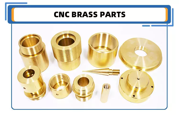
China Best Sales OEM Precision Custom Parts CNC Machining Tractor Stainless Aluminum Brass Parts near me manufacturer

Product Description

LCH(HangZhou WeiHangZhoug Precision Metal Co., Ltd.)was found in 2008,with a total investment of $1.5 million,over 4,500 square meters,equiped with the most advanced high precision CNC Milling machine(30sets), CNC  turning machine(32sets),CNC machining center,automatic lathe and various kinds of secondary processing equipment more than 80 sets.

Don’t hesitate to contact us,best Price best quality best service to you.

Customize various parts with CNC turning/CNC milling/CNC lathe/Casting parts( OEM & ODM)

Send us 3D drawing,we will help make it true!!!
 

1.Aluminum/Brass/ stainless steel Precision Product 2.Extrusion/ Profile
3.Hardware 4.Injection molding
5.Aluminum Frame 6.Furniture Part
7.Aluminum Office and Living Product 8.CNC Precision Milling Part
9.CNC Precision Turning Part 10.Punch& Stamping& Stretching& Riveting& Assembly
11.Die Casting& Welding& Forging& Bending Part 12.Medical Aluminum Part
13.Aluminum Pipe 14.Large Cross-section/ High Challenge Heat Sink
15.Mechanical Industrial product/ Auto Part 16.LED Aluminum Accessory
17.Mold Design and Manufacture 18.Surface treatment

1.We are True manufacture with competitive price and fast lead time.

2.we have 2 platform:alibaba & made in China,Rich export experience.

3.High quality and best services,Advanced equipment & Professional experience.

Product Description

High Precision! High-End Finish! Excellent Quality! Best Machining!

(1).Material:Brass/ aluminum/iron/Tin/ stainless steel
(2).Surface Finished: Anodize &Sandblasting
(3).Process: CNC Turning
(4).Tolerance:0.02mm

Parts Information:
(1). Applicable Material—Aluminum/zinc alloy, iron, steel alloy, plastic, brass, steel, and stainless steel
(2). Surface treatment—polishing, zinc plating, nickel plating, chrome plating, anodizing.
(3). Payment Terms: 40% deposit before production and 60% balance before arrange shipping                                                           
(4). Packaging: Standard package/ Pallet or container/ as per customized specifications.
(5). Shipment Terms: Express & air freight is preferred / sea freight/ as per customized specifications.

We have  professional engineers,advanced equipment.more than 5, 000sqm workshop and about 60 sets CNC turning and milling machine make us a modernized and standardized factory. Now we have more than 100 workers, and 5 engineers, as well as 26 professional technicians. Our well-equipped CNC machine workshop has a comprehensive range of precision machining center, milling and turning equipment, all using CNC technology, which enables us to meet the exacting demands of our customers

How we can keep the high quality parts always?

1.All our material will be tested by SGS before production

2. Full control of process:
(1).During the part production,our QC worker will inspect the part size every 1 hour,this will help us to keep the correct tolerance during production
(2). When the parts machining finished,they will be arranged to have surface finished(such as anodize or powder coated),after that,our QC worker will inspect the parts again,because after surface finished,part tolerance may be difference sometimes,if there is any defective parts we found,we will pick them out directly
(3). Before shipping,our package worker will check the part surface and see if there is any scrach or any other thing that affect the part looking,if yes,pick them out.

Customer comments

Conclusion
Thanks for your kind attention, looking forward to your inquiry and we ensure tip top quality products with the best lead-time being provided!any questions just feel free to ask me.Welcome to our factory,best wishes to you!


How to Compare Different Types of Spur Gears

When comparing different types of spur gears, there are several important considerations to take into account. The main considerations include the following: Common applications, Pitch diameter, and Addendum circle. Here we will look at each of these factors in more detail. This article will help you understand what each type of spur gear can do for you. Whether you’re looking to power an electric motor or a construction machine, the right gear for the job will make the job easier and save you money in the long run.
Gear

Common applications

Among its many applications, a spur gear is widely used in airplanes, trains, and bicycles. It is also used in ball mills and crushers. Its high speed-low torque capabilities make it ideal for a variety of applications, including industrial machines. The following are some of the common uses for spur gears. Listed below are some of the most common types. While spur gears are generally quiet, they do have their limitations.
A spur gear transmission can be external or auxiliary. These units are supported by front and rear casings. They transmit drive to the accessory units, which in turn move the machine. The drive speed is typically between 5000 and 6000 rpm or 20,000 rpm for centrifugal breathers. For this reason, spur gears are typically used in large machinery. To learn more about spur gears, watch the following video.
The pitch diameter and diametral pitch of spur gears are important parameters. A diametral pitch, or ratio of teeth to pitch diameter, is important in determining the center distance between 2 spur gears. The center distance between 2 spur gears is calculated by adding the radius of each pitch circle. The addendum, or tooth profile, is the height by which a tooth projects above the pitch circle. Besides pitch, the center distance between 2 spur gears is measured in terms of the distance between their centers.
Another important feature of a spur gear is its low speed capability. It can produce great power even at low speeds. However, if noise control is not a priority, a helical gear is preferable. Helical gears, on the other hand, have teeth arranged in the opposite direction of the axis, making them quieter. However, when considering the noise level, a helical gear will work better in low-speed situations.

Construction

The construction of spur gear begins with the cutting of the gear blank. The gear blank is made of a pie-shaped billet and can vary in size, shape, and weight. The cutting process requires the use of dies to create the correct gear geometry. The gear blank is then fed slowly into the screw machine until it has the desired shape and size. A steel gear blank, called a spur gear billet, is used in the manufacturing process.
A spur gear consists of 2 parts: a centre bore and a pilot hole. The addendum is the circle that runs along the outermost points of a spur gear’s teeth. The root diameter is the diameter at the base of the tooth space. The plane tangent to the pitch surface is called the pressure angle. The total diameter of a spur gear is equal to the addendum plus the dedendum.
The pitch circle is a circle formed by a series of teeth and a diametrical division of each tooth. The pitch circle defines the distance between 2 meshed gears. The center distance is the distance between the gears. The pitch circle diameter is a crucial factor in determining center distances between 2 mating spur gears. The center distance is calculated by adding the radius of each gear’s pitch circle. The dedendum is the height of a tooth above the pitch circle.
Other considerations in the design process include the material used for construction, surface treatments, and number of teeth. In some cases, a standard off-the-shelf gear is the most appropriate choice. It will meet your application needs and be a cheaper alternative. The gear will not last for long if it is not lubricated properly. There are a number of different ways to lubricate a spur gear, including hydrodynamic journal bearings and self-contained gears.
Gear

Addendum circle

The pitch diameter and addendum circle are 2 important dimensions of a spur gear. These diameters are the overall diameter of the gear and the pitch circle is the circle centered around the root of the gear’s tooth spaces. The addendum factor is a function of the pitch circle and the addendum value, which is the radial distance between the top of the gear tooth and the pitch circle of the mating gear.
The pitch surface is the right-hand side of the pitch circle, while the root circle defines the space between the 2 gear tooth sides. The dedendum is the distance between the top of the gear tooth and the pitch circle, and the pitch diameter and addendum circle are the 2 radial distances between these 2 circles. The difference between the pitch surface and the addendum circle is known as the clearance.
The number of teeth in the spur gear must not be less than 16 when the pressure angle is 20 degrees. However, a gear with 16 teeth can still be used if its strength and contact ratio are within design limits. In addition, undercutting can be prevented by profile shifting and addendum modification. However, it is also possible to reduce the addendum length through the use of a positive correction. However, it is important to note that undercutting can happen in spur gears with a negative addendum circle.
Another important aspect of a spur gear is its meshing. Because of this, a standard spur gear will have a meshing reference circle called a Pitch Circle. The center distance, on the other hand, is the distance between the center shafts of the 2 gears. It is important to understand the basic terminology involved with the gear system before beginning a calculation. Despite this, it is essential to remember that it is possible to make a spur gear mesh using the same reference circle.

Pitch diameter

To determine the pitch diameter of a spur gear, the type of drive, the type of driver, and the type of driven machine should be specified. The proposed diametral pitch value is also defined. The smaller the pitch diameter, the less contact stress on the pinion and the longer the service life. Spur gears are made using simpler processes than other types of gears. The pitch diameter of a spur gear is important because it determines its pressure angle, the working depth, and the whole depth.
The ratio of the pitch diameter and the number of teeth is called the DIAMETRAL PITCH. The teeth are measured in the axial plane. The FILLET RADIUS is the curve that forms at the base of the gear tooth. The FULL DEPTH TEETH are the ones with the working depth equal to 2.000 divided by the normal diametral pitch. The hub diameter is the outside diameter of the hub. The hub projection is the distance the hub extends beyond the gear face.
A metric spur gear is typically specified with a Diametral Pitch. This is the number of teeth per inch of the pitch circle diameter. It is generally measured in inverse inches. The normal plane intersects the tooth surface at the point where the pitch is specified. In a helical gear, this line is perpendicular to the pitch cylinder. In addition, the pitch cylinder is normally normal to the helix on the outside.
The pitch diameter of a spur gear is typically specified in millimeters or inches. A keyway is a machined groove on the shaft that fits the key into the shaft’s keyway. In the normal plane, the pitch is specified in inches. Involute pitch, or diametral pitch, is the ratio of teeth per inch of diameter. While this may seem complicated, it’s an important measurement to understand the pitch of a spur gear.
gear

Material

The main advantage of a spur gear is its ability to reduce the bending stress at the tooth no matter the load. A typical spur gear has a face width of 20 mm and will fail when subjected to 3000 N. This is far more than the yield strength of the material. Here is a look at the material properties of a spur gear. Its strength depends on its material properties. To find out what spur gear material best suits your machine, follow the following steps.
The most common material used for spur gears is steel. There are different kinds of steel, including ductile iron and stainless steel. S45C steel is the most common steel and has a 0.45% carbon content. This type of steel is easily obtainable and is used for the production of helical, spur, and worm gears. Its corrosion resistance makes it a popular material for spur gears. Here are some advantages and disadvantages of steel.
A spur gear is made of metal, plastic, or a combination of these materials. The main advantage of metal spur gears is their strength to weight ratio. It is about 1 third lighter than steel and resists corrosion. While aluminum is more expensive than steel and stainless steel, it is also easier to machine. Its design makes it easy to customize for the application. Its versatility allows it to be used in virtually every application. So, if you have a specific need, you can easily find a spur gear that fits your needs.
The design of a spur gear greatly influences its performance. Therefore, it is vital to choose the right material and measure the exact dimensions. Apart from being important for performance, dimensional measurements are also important for quality and reliability. Hence, it is essential for professionals in the industry to be familiar with the terms used to describe the materials and parts of a gear. In addition to these, it is essential to have a good understanding of the material and the dimensional measurements of a gear to ensure that production and purchase orders are accurate.

China Best Sales OEM Precision Custom Parts CNC Machining Tractor Stainless Aluminum Brass Parts     near me manufacturer China Best Sales OEM Precision Custom Parts CNC Machining Tractor Stainless Aluminum Brass Parts     near me manufacturer

China high quality Shagnhai CZPT Tractor Parts Engine Parts wholesaler

Product Description

Kubota Tractor parts

RELATED PRODUCTS

KUBOTA TRACTOR PARTS :M6040,M7040,M9540,L3408,L4508,L3608,L4708

KUBOTA HARVESTER PARTS:PRO688,PRO758,PRO988,DC60,DC68G,DC70,
                                                    DC70PLUS,DC95,DC105

KUBOTA ENGINE PARTS:V2203,V2403,V2603,V3000,V3600,V3800,D1105,D782,D1803

KUBOTA  RICE TRANSPLANTER PARTS:SVP-6CMD,SPV-8CMD,NSPU-68CMD

PACKAING AND SHIPPING

OUR SERVICES

Product: We can provide high quality products with competitive price.

Production Capacity: we have good production capacity and we have enough spare parts stock and
can start to pack at once when you confirm your order.

Online Service: We will reply you at once when we get your enquiry, 24hours online service for you.
Welcome to contact us by email, ,viber,IMO

COMPANY INFORMATION 

Our Company is a professional agricultural machinery spare parts Manufacturer in China,
We specializes in agricultural machinery and accessories, we have a wealth of experience
in parts development, processing, production, so we are well aware of market demand and
can provide good products for our customers.We have been export to many countries such
as Southeast Asia, Australia, American, South America and Africa. We have enough parts
stock and can send out goods soon when customer place order. Dear Friends, it is our
pleasure to know you and look forward to your cooperation.We have a warehouse of 5000 square meters.


Types of Ball Bearings

In their most basic form, Ball Bearings have 1 common feature – they are made of steel. The majority of these bearings are made of 52100 steel, which has 1 percent chromium and 1 percent carbon. The steel can be hardened by heat trea
tment. 440C stainless steel is used for rusting problems. A cage around the ball balls is traditionally made from thin steel. However, some bearings use molded plastic cages to save money and friction.
bearing

Single-row designs

Steel linear translation stages often use single-row designs for ball bearings. These types of bearings provide smooth linear travel and can withstand high loads. The material steel has a high modulus of elasticity and a high stiffness, as well as a lower thermal expansion than aluminum. For these reasons, steel is the material of choice for a ball bearing in a typical user environment. Single-row designs for ball bearings are also suitable for applications in humid or corrosive environments.
Single-row designs for ball bearings are available in a variety of sizes and are axially adjustable. They have a high radial capacity, but require relatively little space. Single-row deep groove ball bearings with snap rings are STN 02 4605 or R47, respectively. Bearings with snap rings are identified by a suffix such as NR. They may not have seals or shields installed.
These single-row angular contact ball bearings are capable of supporting axial and radial loads. In a two-raceway arrangement, the radial load on bearing A causes a radial load to act on bearing B. Both axial and radial forces are transmitted between single-row angular contact ball bearings, and the resulting internal force must be taken into account to calculate equivalent dynamic bearing loads P.
Single-row deep groove ball bearings are the most common type of ball bearings. These bearings are designed with only 1 row of rolling elements. The single-row design is simple and durable, which makes it ideal for high-speed applications. Single-row designs for ball bearings are also available in various bore sizes. They can also come in a variety of shapes and are non-separable. If you need a high-speed bearing, you may want to opt for a double-row design.
In addition to single-row designs for ball bearings, you can choose ceramic or steel ball bearings. Ceramic balls are considerably harder than steel balls, but they are not as hard as steel. Hence, ceramic bearings are stiffer than steel ball bearings, resulting in increased stress on the outer race groove and lower load capacity. This is a great benefit for those who need the bearings to be lightweight and strong.
The difference between single-row and double-row designs is in the way that the inner and outer ring are installed. A single-row design places the inner ring in an eccentric position relative to the outer ring. The 2 rings are in contact at 1 point, which causes a large gap in the bearing. The balls are then inserted through the gap. As a result, the balls are evenly distributed throughout the bearing, which forces the inner and outer rings to become concentric.
Deep-groove ball bearings are 1 of the most popular types of ball bearings. They are available in different designs, including snap-ring, seal and shield arrangements. The race diameter of a deep-groove ball bearing is close to the ball’s diameter. These types of bearings are suited for heavy loads, and their axial and radial support are excellent. Their main drawback is that the contact angle cannot be adjusted to accommodate a wide range of relative loads.
bearing

Ceramic hybrid ball bearings

Hybrid ball bearings with ceramic balls have numerous advantages. They feature improved kinematic behavior and require less lubrication. Consequently, they can reduce operating costs. Additionally, their low thermal expansion coefficient allows for smaller changes in contact angle and preload variations, and they can retain tolerances. Furthermore, ceramic hybrid ball bearings have significantly increased life spans compared to conventional steel-steel ball bearings, with up to 10 times the lifespan.
Although ceramic bearings can be used in automotive applications, many people believe that they’re a poor choice for bicycle hubs. They don’t reduce weight and only work well in high-rpm environments. As a result, many cyclists don’t even bother with ceramic-based bearings. However, both Paul Lew and Alan are of the opinion that ceramic bearings are best suited for industrial or medical equipment applications. Furthermore, Paul and Alan believe that they are ideal for high-altitude drone motors.
Another advantage of ceramic hybrid ball bearings is that they use less friction than conventional steel-based balls. They are also more durable, requiring less lubrication than steel-based bearings. Furthermore, the lower friction and rolling resistance associated with ceramic-based ball bearings means that they can last 10 times longer than steel-based bearings. A ceramic-based hybrid ball bearing can be used for applications where speed and lubrication are critical.
Ceramic hybrid ball bearings feature both steel and silicon nitride balls. Silicon nitride balls have 50% more modulus of elasticity than steel balls and can improve accuracy and precision. Ceramic balls also have a smoother surface finish than steel balls, which reduces vibration and spindle deflection. These benefits result in increased speed and improved production quality. In addition to this, ceramic balls can also reduce the operating temperature, enhancing the work environment.
Hybrid bearings are a popular alternative to steel bearings. They have some benefits over traditional steel bearings, and are becoming a popular choice for engineered applications. Hybrid bearings are ideal for high speed machines. The material used to manufacture ceramic balls is a high-quality alloy, and is comparatively inexpensive. But you must understand that lubrication is still necessary for hybrid bearings. If you are not careful, you may end up wasting money.
These ball bearings can be used in many industries and applications, and they are widely compatible with most metals. The main advantage of hybrid ball bearings is that they are very durable. While steel balls tend to corrode and wear out, ceramic ball bearings can withstand these conditions while minimizing maintenance and replacement costs. The benefits of hybrid ball bearings are clear. So, consider switching to these newer types of ball bearings.
bearing

Self-aligning ball bearings

Self-aligning ball bearings are a good choice for many applications. They are a great alternative to traditional ball bearings, and they are ideal for rotating applications in which the shaft must move in several directions. They are also ideal for use in rotating parts where a tight tolerance is necessary. You can choose between 2 types: plain and flex shaft. Read on to find out which 1 will suit your needs.
Self-aligning ball bearings are designed with a higher axial load carrying capacity than single-row radial deep groove ball bearings. The amount of axial load carrying capacity is dependent upon the pressure angle. These bearings have a hollow raceway in the outer ring that allows the inner ring to pivot without friction. They are often used for high-speed applications. Because of their design, they are highly accurate.
Self-aligning ball bearings are radial bearings that feature 2 rows of balls in a spherical outer ring. They also feature 2 deep uninterrupted raceway grooves in the inner ring. Their unique features make them an excellent choice for applications where shaft deflection is a significant factor. Despite their small size, they have a high level of precision and can withstand heavy loads.
Self-aligning ball bearings can compensate for misalignment in shaft applications. The inner ring and ball assembly are positioned inside an outer ring containing a curved raceway. This spherical design allows the balls and cage to deflect and re-align around the bearing center. These bearings are also ideal for applications where shaft deflection is significant, such as in simple woodworking machinery.
Another type of self-aligning ball bearing uses a common concave outer race. Both balls and outer races automatically compensate for angular misalignment caused by machining, assembly, and deflections. Compared to spherical rollers, they have lower frictional losses than their spherical counterparts. Self-alignment ball bearings also have lower vibration levels compared to other types of bearings.
Self-aligning ball bearings operate in misaligned applications because their spherical outer raceway can accommodate misalignment. This design allows them to work in applications where shaft deflection or housing deformation is common. They are therefore more suitable for low to medium-sized loads. The only real drawback to self-aligning ball bearings is their price. If you need to purchase a self-aligning ball bearing for your next project, you can expect to pay around $1500.

China high quality Shagnhai CZPT Tractor Parts Engine Parts     wholesaler China high quality Shagnhai CZPT Tractor Parts Engine Parts     wholesaler

China Standard China Belarus Mtz Tractor Spare Parts near me manufacturer

Product Description

China Belarus Mtz Tractor Spare Parts

Product Description

1. Precision CNC machining parts strictly follow customers’ drawing, packing, and quality requirements.
2. Tolerance: between+/-0.01mm;
3. The high-tech CMM inspector to ensure the quality;
4. Full-Experienced engineers and well professional trained workers;
5. Fast delivery time;
6. Professional advice for our customers; 

Detailed Photos


Product Parameters

Our advantage of cnc machining:

Business Type Beyond the Manufacturer and strong organized ability in the industrial
Benefits 1. Deeper industrial experience at CNC machining parts service for more than 10-years,our customer’s requirement is our 1st priority.
2. 2D or 3D files is available;
3. We trust the quality priority and we insist the good quality should be based on the customers’ satisfied;
4. Without any MOQ requirement;
5.Faster delivery time;
6. Customized size and specification /OEM available
7. Near ZheJiang Port

The material

 
 Materials Accept
 
Stainless Steel SS201, SS303, SS304, SS316 etc.
Steel Q235, 20#, 45#,
Brass C36000 ( C26800), C37700 ( HPb59), C38500( HPb58), C27200(CuZn37) , C28000(CuZn40)
Iron 1213, 12L14,1215 etc.
Bronze C51000, C52100, C54400, etc.
Aluminum Al6061, Al6063,AL7075,AL5052 etc
Plastic ABS,POM,PC(Poly-Carbonate),PC+GF,PA(nylon),PA+GF,
PMMA(acrylic)PEEK,PEI etc)

Packaging & Shipping


  1. We prefer DHL or TNT express or other air freight between 1kg-100kg.
  2. we prefer sea freight more than 100kg or more than 1CBM
  3. As per customized specifications.


Company Profile

About us
HangZhou Emitech Technology Co.,Ltd is located in HangZhou City, ZheJiang  Province, Which closed the ZheJiang .The Emitech Technology is mainly engaged in the CNC Machinery Industrial Service for 15 years. Our Parts are sold to Europe, America, Japan, South Korea and China in various kinds of industrial.At present, Our company has CNC Turning machines and CNC centers and equip with professional quality and testing instruments.We have full OEM Experience from worldwide, providing them with One-stop solutions for a broad range of applications.We look forward to cooperating with you!


Our Advantages

1. Precision CNC machining parts strictly follow customer’s drawing,packing and quality requirement.
2. Tolerance: between+/-0.01mm;
3. The high-tech CMM inspector to ensure the quality;
4. Full-Experienced engineers and well professional trained workers;
5. Fast delivery time;
6. Professional advice for our customers; 

After Sales Service

Precision Custom Aluminum Parts machining manufacturer
We usually provide 12 Months repair service. If our duty, we will respond to send the new parts.

Our Service


Our Processing CNC center, CNC milling, CNC turning, drilling, grinding, bending, stamping, tapping,
Surface finish Polishing, sandblasting, Zinc-plated, nickel-plated, chrome-plated, silver-plated, gold-plated, imitation gold-plated,
Tolerance 0.05mm~0.1mm
QC System 100% inspection before shipment
Drawing format CAD / PDF/ DWG/ IGS/ STEP
Packaging Plastic bag/Standard package / Carton or Pallet / As per customized specifications
Payment Terms 30 -50%T/T in advance, 70-50% balance before delivery; Pay Pal or Western Union is acceptable.
Trade terms EXW, FOB, CIF, As per the customer’s request
Shipment Terms

1)We prefer DHL or TNT express or other air freight between 1kg-100kg.

2) we prefer sea freight more than 100kg or more than 1CBM
3) As per customized specifications.

Note The CNC machining parts are usually custom-made based on the customer’s drawings and samples. So we need the Down Payment


Analytical Approaches to Estimating Contact Pressures in Spline Couplings

A spline coupling is a type of mechanical connection between 2 rotating shafts. It consists of 2 parts – a coupler and a coupling. Both parts have teeth which engage and transfer loads. However, spline couplings are typically over-dimensioned, which makes them susceptible to fatigue and static behavior. Wear phenomena can also cause the coupling to fail. For this reason, proper spline coupling design is essential for achieving optimum performance.
splineshaft

Modeling a spline coupling

Spline couplings are becoming increasingly popular in the aerospace industry, but they operate in a slightly misaligned state, causing both vibrations and damage to the contact surfaces. To solve this problem, this article offers analytical approaches for estimating the contact pressures in a spline coupling. Specifically, this article compares analytical approaches with pure numerical approaches to demonstrate the benefits of an analytical approach.
To model a spline coupling, first you create the knowledge base for the spline coupling. The knowledge base includes a large number of possible specification values, which are related to each other. If you modify 1 specification, it may lead to a warning for violating another. To make the design valid, you must create a spline coupling model that meets the specified specification values.
After you have modeled the geometry, you must enter the contact pressures of the 2 spline couplings. Then, you need to determine the position of the pitch circle of the spline. In Figure 2, the centre of the male coupling is superposed to that of the female spline. Then, you need to make sure that the alignment meshing distance of the 2 splines is the same.
Once you have the data you need to create a spline coupling model, you can begin by entering the specifications for the interface design. Once you have this data, you need to choose whether to optimize the internal spline or the external spline. You’ll also need to specify the tooth friction coefficient, which is used to determine the stresses in the spline coupling model 20. You should also enter the pilot clearance, which is the clearance between the tip 186 of a tooth 32 on 1 spline and the feature on the mating spline.
After you have entered the desired specifications for the external spline, you can enter the parameters for the internal spline. For example, you can enter the outer diameter limit 154 of the major snap 54 and the minor snap 56 of the internal spline. The values of these parameters are displayed in color-coded boxes on the Spline Inputs and Configuration GUI screen 80. Once the parameters are entered, you’ll be presented with a geometric representation of the spline coupling model 20.

Creating a spline coupling model 20

The spline coupling model 20 is created by a product model software program 10. The software validates the spline coupling model against a knowledge base of configuration-dependent specification constraints and relationships. This report is then input to the ANSYS stress analyzer program. It lists the spline coupling model 20’s geometric configurations and specification values for each feature. The spline coupling model 20 is automatically recreated every time the configuration or performance specifications of the spline coupling model 20 are modified.
The spline coupling model 20 can be configured using the product model software program 10. A user specifies the axial length of the spline stack, which may be zero, or a fixed length. The user also enters a radial mating face 148, if any, and selects a pilot clearance specification value of 14.5 degrees or 30 degrees.
A user can then use the mouse 110 to modify the spline coupling model 20. The spline coupling knowledge base contains a large number of possible specification values and the spline coupling design rule. If the user tries to change a spline coupling model, the model will show a warning about a violation of another specification. In some cases, the modification may invalidate the design.
In the spline coupling model 20, the user enters additional performance requirement specifications. The user chooses the locations where maximum torque is transferred for the internal and external splines 38 and 40. The maximum torque transfer location is determined by the attachment configuration of the hardware to the shafts. Once this is selected, the user can click “Next” to save the model. A preview of the spline coupling model 20 is displayed.
The model 20 is a representation of a spline coupling. The spline specifications are entered in the order and arrangement as specified on the spline coupling model 20 GUI screen. Once the spline coupling specifications are entered, the product model software program 10 will incorporate them into the spline coupling model 20. This is the last step in spline coupling model creation.
splineshaft

Analysing a spline coupling model 20

An analysis of a spline coupling model consists of inputting its configuration and performance specifications. These specifications may be generated from another computer program. The product model software program 10 then uses its internal knowledge base of configuration dependent specification relationships and constraints to create a valid three-dimensional parametric model 20. This model contains information describing the number and types of spline teeth 32, snaps 34, and shoulder 36.
When you are analysing a spline coupling, the software program 10 will include default values for various specifications. The spline coupling model 20 comprises an internal spline 38 and an external spline 40. Each of the splines includes its own set of parameters, such as its depth, width, length, and radii. The external spline 40 will also contain its own set of parameters, such as its orientation.
Upon selecting these parameters, the software program will perform various analyses on the spline coupling model 20. The software program 10 calculates the nominal and maximal tooth bearing stresses and fatigue life of a spline coupling. It will also determine the difference in torsional windup between an internal and an external spline. The output file from the analysis will be a report file containing model configuration and specification data. The output file may also be used by other computer programs for further analysis.
Once these parameters are set, the user enters the design criteria for the spline coupling model 20. In this step, the user specifies the locations of maximum torque transfer for both the external and internal spline 38. The maximum torque transfer location depends on the configuration of the hardware attached to the shafts. The user may enter up to 4 different performance requirement specifications for each spline.
The results of the analysis show that there are 2 phases of spline coupling. The first phase shows a large increase in stress and vibration. The second phase shows a decline in both stress and vibration levels. The third stage shows a constant meshing force between 300N and 320N. This behavior continues for a longer period of time, until the final stage engages with the surface.
splineshaft

Misalignment of a spline coupling

A study aimed to investigate the position of the resultant contact force in a spline coupling engaging teeth under a steady torque and rotating misalignment. The study used numerical methods based on Finite Element Method (FEM) models. It produced numerical results for nominal conditions and parallel offset misalignment. The study considered 2 levels of misalignment – 0.02 mm and 0.08 mm – with different loading levels.
The results showed that the misalignment between the splines and rotors causes a change in the meshing force of the spline-rotor coupling system. Its dynamics is governed by the meshing force of splines. The meshing force of a misaligned spline coupling is related to the rotor-spline coupling system parameters, the transmitting torque, and the dynamic vibration displacement.
Despite the lack of precise measurements, the misalignment of splines is a common problem. This problem is compounded by the fact that splines usually feature backlash. This backlash is the result of the misaligned spline. The authors analyzed several splines, varying pitch diameters, and length/diameter ratios.
A spline coupling is a two-dimensional mechanical system, which has positive backlash. The spline coupling is comprised of a hub and shaft, and has tip-to-root clearances that are larger than the backlash. A form-clearance is sufficient to prevent tip-to-root fillet contact. The torque on the splines is transmitted via friction.
When a spline coupling is misaligned, a torque-biased thrust force is generated. In such a situation, the force can exceed the torque, causing the component to lose its alignment. The two-way transmission of torque and thrust is modeled analytically in the present study. The analytical approach provides solutions that can be integrated into the design process. So, the next time you are faced with a misaligned spline coupling problem, make sure to use an analytical approach!
In this study, the spline coupling is analyzed under nominal conditions without a parallel offset misalignment. The stiffness values obtained are the percentage difference between the nominal pitch diameter and load application diameter. Moreover, the maximum percentage difference in the measured pitch diameter is 1.60% under a torque of 5000 N*m. The other parameter, the pitch angle, is taken into consideration in the calculation.

China Standard China Belarus Mtz Tractor Spare Parts     near me manufacturer China Standard China Belarus Mtz Tractor Spare Parts     near me manufacturer

China Best Sales Sino CZPT A7 Tractor Truck Steel Body Spare Parts with Great quality

Product Description


Sino CZPT A7 Tractor Truck Steel Body Spare Parts

  1. Detachable kingpin, easy to change;
  2.Strong mechanical ladder;
  3.China best brand CZPT axle and good brand Triangle brand tyre;
  4.Enforeced main and side beam, suitable for bad road condition;


Packaging & Shipping

Nude and waxed by bulk cargo ship or Ro-Ro ship.
Three units could be stacked up together to save unit sea freight cost.

Our Services

1. Reply your inquiry in 12 working hours;

2. Experienced staffs answer all your questions;

3. Customer’s design is available for certain products(OEM);

4. Spare parts for all types of engine machinery with reasonable price;

5. Different brand of trucks can be provided with competitive price.

After-Sales Service 
1.12months for 3 key parts (engine, transmission, axle). 
2.Tracking service time: lifelong. 
3.Third-party service for overseas client.  
4.Use the steps Description 
5.Parts supply on time

Othe types of semi trailers we can produce
1.Low bed semi-trailer : transport heavy duty machinery 
2.Fuel tank semi-trailer : transport oil,gasoline,diesel,fuel,etc. 
3.Flatbed container semi-trailer : carry 1x40ft/2x20ft/1x20ft container 
4.Van type semi-trailer  
5.Warehouse gate semi-trailer 
6.Bulk powder semi-trailer 
7.Dump trailer 
8.Side wall semi-trailer
Cutomized cement bulker trailer welcomed. 

FAQ

1. Q: Are you a manufacturer or trading company?    

    A: We are manufacturer.

2. Q: What about your product’s quality?                        

    A:”Quality is priority.” We always attach great importance to quality controlling from the very beginning. 

3.Q:What payment do you accept?                                  

   A: T/T, L/C; 

4.Q:What is the MOQ of your products?                          
   A: 1 set. 
 

Anne Jiang

Welcome you and your friends to visit our factory at any time !!!


The Difference Between Planetary Gears and Spur Gears

A spur gear is a type of mechanical drive that turns an external shaft. The angular velocity is proportional to the rpm and can be easily calculated from the gear ratio. However, to properly calculate angular velocity, it is necessary to know the number of teeth. Fortunately, there are several different types of spur gears. Here’s an overview of their main features. This article also discusses planetary gears, which are smaller, more robust, and more power-dense.
Planetary gears are a type of spur gear

One of the most significant differences between planetary gears and spurgears is the way that the 2 share the load. Planetary gears are much more efficient than spurgears, enabling high torque transfer in a small space. This is because planetary gears have multiple teeth instead of just one. They are also suitable for intermittent and constant operation. This article will cover some of the main benefits of planetary gears and their differences from spurgears.
While spur gears are more simple than planetary gears, they do have some key differences. In addition to being more basic, they do not require any special cuts or angles. Moreover, the tooth shape of spur gears is much more complex than those of planetary gears. The design determines where the teeth make contact and how much power is available. However, a planetary gear system will be more efficient if the teeth are lubricated internally.
In a planetary gear, there are 3 shafts: a sun gear, a planet carrier, and an external ring gear. A planetary gear is designed to allow the motion of 1 shaft to be arrested, while the other 2 work simultaneously. In addition to two-shaft operation, planetary gears can also be used in three-shaft operations, which are called temporary three-shaft operations. Temporary three-shaft operations are possible through frictional coupling.
Among the many benefits of planetary gears is their adaptability. As the load is shared between several planet gears, it is easier to switch gear ratios, so you do not need to purchase a new gearbox for every new application. Another major benefit of planetary gears is that they are highly resistant to high shock loads and demanding conditions. This means that they are used in many industries.
Gear

They are more robust

An epicyclic gear train is a type of transmission that uses concentric axes for input and output. This type of transmission is often used in vehicles with automatic transmissions, such as a Lamborghini Gallardo. It is also used in hybrid cars. These types of transmissions are also more robust than conventional planetary gears. However, they require more assembly time than a conventional parallel shaft gear.
An epicyclic gearing system has 3 basic components: an input, an output, and a carrier. The number of teeth in each gear determines the ratio of input rotation to output rotation. In some cases, an epicyclic gear system can be made with 2 planets. A third planet, known as the carrier, meshes with the second planet and the sun gear to provide reversibility. A ring gear is made of several components, and a planetary gear may contain many gears.
An epicyclic gear train can be built so that the planet gear rolls inside the pitch circle of an outer fixed gear ring, or “annular gear.” In such a case, the curve of the planet’s pitch circle is called a hypocycloid. When epicycle gear trains are used in combination with a sun gear, the planetary gear train is made up of both types. The sun gear is usually fixed, while the ring gear is driven.
Planetary gearing, also known as epicyclic gear, is more durable than other types of transmissions. Because planets are evenly distributed around the sun, they have an even distribution of gears. Because they are more robust, they can handle higher torques, reductions, and overhung loads. They are also more energy-dense and robust. In addition, planetary gearing is often able to be converted to various ratios.
Gear

They are more power dense

The planet gear and ring gear of a compound planetary transmission are epicyclic stages. One part of the planet gear meshes with the sun gear, while the other part of the gear drives the ring gear. Coast tooth flanks are used only when the gear drive works in reversed load direction. Asymmetry factor optimization equalizes the contact stress safety factors of a planetary gear. The permissible contact stress, sHPd, and the maximum operating contact stress (sHPc) are equalized by asymmetry factor optimization.
In addition, epicyclic gears are generally smaller and require fewer space than helical ones. They are commonly used as differential gears in speed frames and in looms, where they act as a Roper positive let off. They differ in the amount of overdrive and undergearing ratio they possess. The overdrive ratio varies from 15 percent to 40 percent. In contrast, the undergearing ratio ranges from 0.87:1 to 69%.
The TV7-117S turboprop engine gearbox is the first known application of epicyclic gears with asymmetric teeth. This gearbox was developed by the CZPT Corporation for the Ilyushin Il-114 turboprop plane. The TV7-117S’s gearbox arrangement consists of a first planetary-differential stage with 3 planet gears and a second solar-type coaxial stage with 5 planet gears. This arrangement gives epicyclic gears the highest power density.
Planetary gearing is more robust and power-dense than other types of gearing. They can withstand higher torques, reductions, and overhung loads. Their unique self-aligning properties also make them highly versatile in rugged applications. It is also more compact and lightweight. In addition to this, epicyclic gears are easier to manufacture than planetary gears. And as a bonus, they are much less expensive.

They are smaller

Epicyclic gears are small mechanical devices that have a central “sun” gear and 1 or more outer intermediate gears. These gears are held in a carrier or ring gear and have multiple mesh considerations. The system can be sized and speeded by dividing the required ratio by the number of teeth per gear. This process is known as gearing and is used in many types of gearing systems.
Planetary gears are also known as epicyclic gearing. They have input and output shafts that are coaxially arranged. Each planet contains a gear wheel that meshes with the sun gear. These gears are small and easy to manufacture. Another advantage of epicyclic gears is their robust design. They are easily converted into different ratios. They are also highly efficient. In addition, planetary gear trains can be designed to operate in multiple directions.
Another advantage of epicyclic gearing is their reduced size. They are often used for small-scale applications. The lower cost is associated with the reduced manufacturing time. Epicyclic gears should not be made on N/C milling machines. The epicyclic carrier should be cast and tooled on a single-purpose machine, which has several cutters cutting through material. The epicyclic carrier is smaller than the epicyclic gear.
Epicyclic gearing systems consist of 3 basic components: an input, an output, and a stationary component. The number of teeth in each gear determines the ratio of input rotation to output rotation. Typically, these gear sets are made of 3 separate pieces: the input gear, the output gear, and the stationary component. Depending on the size of the input and output gear, the ratio between the 2 components is greater than half.
Gear

They have higher gear ratios

The differences between epicyclic gears and regular, non-epicyclic gears are significant for many different applications. In particular, epicyclic gears have higher gear ratios. The reason behind this is that epicyclic gears require multiple mesh considerations. The epicyclic gears are designed to calculate the number of load application cycles per unit time. The sun gear, for example, is +1300 RPM. The planet gear, on the other hand, is +1700 RPM. The ring gear is also +1400 RPM, as determined by the number of teeth in each gear.
Torque is the twisting force of a gear, and the bigger the gear, the higher the torque. However, since the torque is also proportional to the size of the gear, bigger radii result in lower torque. In addition, smaller radii do not move cars faster, so the higher gear ratios do not move at highway speeds. The tradeoff between speed and torque is the gear ratio.
Planetary gears use multiple mechanisms to increase the gear ratio. Those using epicyclic gears have multiple gear sets, including a sun, a ring, and 2 planets. Moreover, the planetary gears are based on helical, bevel, and spur gears. In general, the higher gear ratios of epicyclic gears are superior to those of planetary gears.
Another example of planetary gears is the compound planet. This gear design has 2 different-sized gears on either end of a common casting. The large end engages the sun while the smaller end engages the annulus. The compound planets are sometimes necessary to achieve smaller steps in gear ratio. As with any gear, the correct alignment of planet pins is essential for proper operation. If the planets are not aligned properly, it may result in rough running or premature breakdown.

China Best Sales Sino CZPT A7 Tractor Truck Steel Body Spare Parts     with Great qualityChina Best Sales Sino CZPT A7 Tractor Truck Steel Body Spare Parts     with Great quality

China factory Farm Machinery, Tractor Parts, OEM Casting Parts Supplier Made in China Customized Professional Foundry wholesaler

Product Description

We are a foundry for casting processed products.
With more than 10 years of experience, our products have been exported to the United States, Germany, Italy, Spain, etc.
Our engineers have more than 10 years experience in quality control and can guarantee the highest quality of castings
A factory that integrates casting, heat treatment, and machining capabilities to achieve lower costs

Process Shell Model Casting,Heat treatment,CNC machining,
Equipment Semi automatic casting line.CNC centers, CNC turning, CNC lathes, line cutting, milling, drilling, grinding
Material ASTM (60-40-18,65-45-12,70-50-05,80-60-03,100-70-03).ect.
Surface Trimming, Deburring,Polishing, Shot blasting, Sand blasting,Tumbling, Powder coating, Anodizing, Chrome, Zinc, Electrophoresis, 
Software Assistance Pro-e/Solid work/UG/Auto CAD
Products Application Auto Parts, Agricultural Machinery Parts, Power Parts, Railway Machinery Parts, Construction Machinery Parts, Elevator Parts.ect.


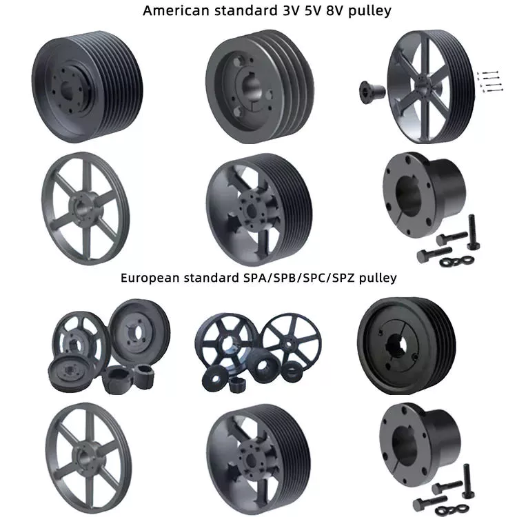
The Mechanical Advantage of a Pulley

A pulley is an important tool for many tasks. The advantage that it offers over a hand-held mechanism is its mechanical advantage. In this article, we’ll discuss the types of pulleys and their applications. We’ll also look at the types of compound pulleys. And, of course, there’s a little bit about the mechanical advantage of a pulley. This article will help you decide whether this tool is right for your needs.
pulley

Mechanical advantage of a pulley

A pulley has a mechanical advantage over a lever because it is able to produce more force over longer distances. The mechanical advantage of a pulley sounds brilliant and could produce energy. But what exactly is this mechanical advantage? Let’s take a look. First, consider how a pulley works. A rope supports a 100kg mass, which requires 500 newtons of force to lift. If the rope supports a 100kg mass, 2 sections of rope can support that load. Using a pulley, you can lift the same weight with half the force.
A pulley’s ideal mechanical advantage is the ratio of the force applied to the total length of the rope. The larger the radius, the greater the mechanical advantage. A pulley made up of 4 rope segments has an ideal mechanical advantage of four. Therefore, a four-segment pulley would multiply the force applied by four. As the numbers on the rope segments are smaller than the total length of the rope, it would be better to use a compound pulley.
The mechanical advantage of a pulley can be calculated by using the T-method. The first step in calculating the mechanical advantage of a pulley is defining the force you need to lift. Then, divide that force by 2 to calculate the amount of force you need to lift the load. Once you know this amount, you can design a pulley to meet your needs. That way, you can achieve the perfect balance between the 2 types of pulleys.

Types of pulleys

The main function of the pulley is to change the direction of the force. The mechanical advantages of a single pulley are two. Ideally, 2 pulleys should have 2 or more mechanical advantages. The mechanical advantage of compound pulleys can be increased to 2 or more. The number of pulleys that make up the composite pulley will determine the mechanical advantage. Certain types of pulleys are combined in 1 housing.
A stepped pulley is a set of pulleys with stepped surfaces. Each face is anchored to the mid-axis in an ordered sequence. This design gives these pulleys their name. They are used to increase and decrease the speed of the driven pulley. Step pulleys are usually used in pairs. They can be straight or stepped, but usually come in pairs.
The 3 main types of pulleys are pulleys, rope pulleys, and chain pulleys. Pulley Pulley systems use mechanics to lift and lower heavy objects. The Greek historian Plutarch credits the invention of the pulley to Archimedes of ancient Sicily. The Mesopotamians used rope pulleys to lift water around 1500 BC, and Stonehenge is said to have been built using a rope pulley system.
pulley

Application of pulley system

The advantages of using a pulley system are numerous. The ability to lift heavy objects is a good example. The pulley system makes it easy for people to lift blocks and other large objects. It can be used in many different applications, from utility elevators to construction cranes. In addition, it is widely used on sailing boats. If you want to learn more about the benefits of a pulley system, keep reading!
You can use the pulley system to water flowers or water plants. Some of them even lowered the pot to make cleaning easier. Pendant lights are another great place to install a pulley system. Climbing and fishing are just some of the activities that utilize the pulley. They are great for fishing and gardening. And since they are so versatile, you can use the pulley system anywhere.
To get the most out of your pulley system, you must choose a product that has all of the above attributes. A high-quality pulley must have a large pulley diameter and be made of sturdy materials. The cables must also be properly supported in the pulleys to ensure a long service life for your investment. A good cable should have minimal cracks and be lubricated. These factors are the most important considerations when choosing a pulley system for your needs.

composite pulley

Composite pulley systems combine 2 or more movable pulleys. These systems maximize the force to move the weight and can also change direction so they can be used to lift weights. Composite pulley systems can be as simple or as complex as your needs. For example, a pulley pulley system uses multiple pulleys on each axis. This method is often used for hoisting building materials.
A compound pulley system has 2 or more rope segments, each of which is pulled up on a load. It can increase lift by making objects move faster. These systems are common on large sailboats and construction sites. Composite pulleys are also available for larger boats. Due to their versatility, they are versatile tools for construction sites and large sailboats. If you have their app, you should consider buying one.
The main advantage of composite pulleys is their versatility. You can use them to lift weights or use them to save energy. Composite pulleys are especially useful for lifting heavy objects. For example, you can tie a paper clip to the end of the rope and pull it up. The flag is then lifted into the air with the help of compound pulleys. Composite pulleys are a great invention and they are often used in construction.

security considerations

There are several safety considerations to consider when using pulleys. The first is Secure Workload (SWL). This value is a general guideline for the maximum weight a pulley can safely handle. It varies according to the height and angle of the pulley. Besides SWL, there are some other factors to consider. Consider each 1 before deciding on the pulley that best suits your needs.
Another safety consideration is the weight of the load. Since the highs of the pulley are higher than the lows, it doubles in weight. The weight of the high point should not exceed 4 kN. The safety factor is calculated by multiplying the strength of the pulley by the weight of the load. Secondary COD has a safety factor of 10:1 and bulletproof primary anchors should be used with pulleys.
If using a chain hoist, you must be trained in the appropriate type of lifting. It is important not to hang on the top hooks of the structure, nor to overload or rig the hooks with multiple slings. You should also avoid corroded or damaged chains, as they can cause the crane to jam or overload. A worn chain can even cause the load to drop.
pulley

Components of a pulley system

Proper design of the pulley system can increase the life of the cables and pulleys. Larger diameter cables should be selected as they are more durable than smaller diameter cables. The cables should also be supported in the pulley grooves. The pulley must be designed to be compatible with the cable and its lubrication should be optimal. Proper lubrication of cables and pulleys will ensure maximum durability and longevity.
The first type of pulley is called a fast pulley. These pulleys are used for quick start and stop of the machine. These pulleys are usually mounted in pairs on the countershaft of the machine. One pulley is tightly mounted on the machine shaft, while the other pulley is fitted with a free-spinning mechanism. When the machine is running, the belt is mounted on the tensioner pulley, and when it is stopped, the belt slides on the independent pulley.
Composite pulley sets reduce the overall effort required by reducing the size of the pulley. These are usually attributed to Archimedes. Flat pulleys are often used in flat belt driven transmission systems. These are used in high-speed, low-power applications. Flat pulley idlers are also used on the back of traditional V-belts.

China factory Farm Machinery, Tractor Parts, OEM Casting Parts Supplier Made in China Customized Professional Foundry     wholesaler China factory Farm Machinery, Tractor Parts, OEM Casting Parts Supplier Made in China Customized Professional Foundry     wholesaler

China high quality CZPT Tractor Hydraulic Pump F0nn600bb Tractor Parts near me supplier

Product Description

FORD Tractor Hydraulic Pump F0NN6
Ford Tractor: 5610, 5640, 6610, 6640, 6810, 7610, 7740, 7840, 8240, 8340

We also support CASE IH, FIAT, FORD, JOHNDEERE, KUBOTA, MF Tractor OEM Pumps, Steering units.

1. OEM quality.
2. Advantage price.
3. Fast delivery.
4. Warranty quality.
5. Support retail and wholesale.
6. Diversified payment methods.
 

Foed Tractor OEM Paump

D0NN6

D8NN6

D8NN6

E1NN6

D0NN6

D8NN6

E6NN3K514AB, 83960261

E6NN3K514EA, 87559440

D5NN6

E6NN3K514PA

E9NN6

82988360

We insist: nobody has, we have; somebody has, we have better.
We embrace: user is priority, quality is priority, service is priority.
We expect: share the fruit of development, create brilliant career, and serve the community together.
Elephant Fluid Power Co.,Ltd Company is willing to start a new journey with you hand in hand!

We are looking for good long business partner and friendship.
If you are interested in our products, please contact me.I’ll give you a favorable quotation.


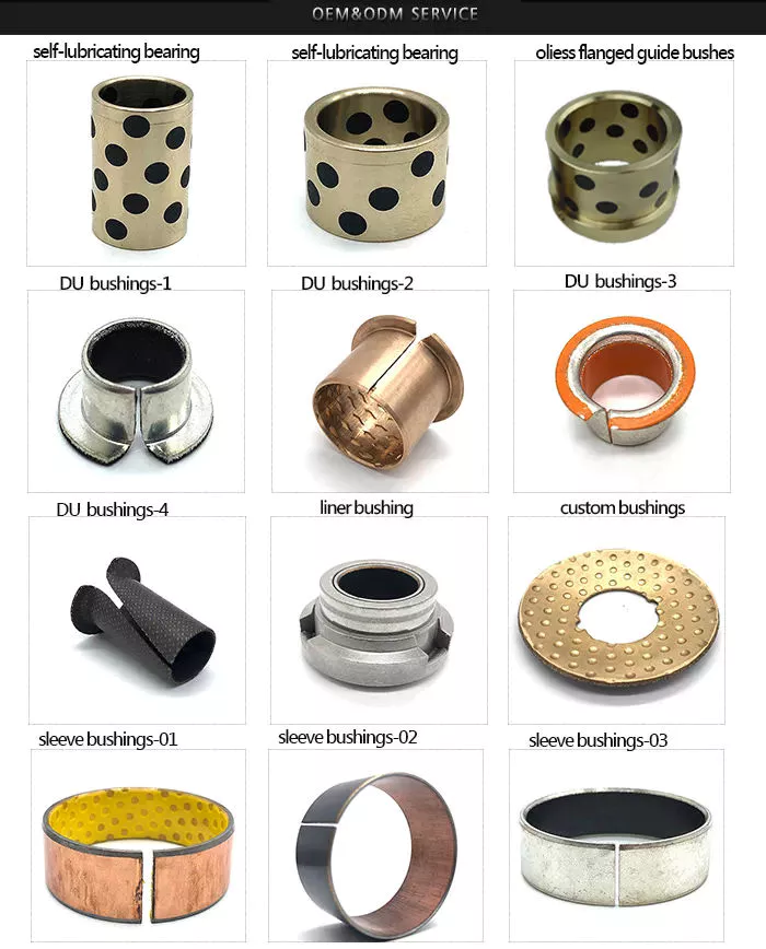
The benefits of rubber bushings and how they work

If you have experienced increased vibration while driving, you know the importance of replacing the control arm bushings. The resulting metal-to-metal contact can cause annoying driving problems and be a threat to your safety. Over time, the control arm bushings begin to wear out, a process that can be exacerbated by harsh driving conditions and environmental factors. Additionally, larger tires that are more susceptible to bushing wear are also prone to increased vibration transfer, especially for vehicles with shorter sidewalls. Additionally, these plus-sized tires, which are designed to fit on larger rims, have a higher risk of transmitting vibrations through the bushings.
bushing

rubber

Rubber bushings are rubber tubes that are glued into the inner or outer curve of a cylindrical metal part. The rubber is made of polyurethane and is usually prestressed to avoid breaking during installation. In some cases, the material is also elastic, so it can slide. These properties make rubber bushings an integral part of a vehicle’s suspension system. Here are some benefits of rubber bushings and how they work.
Rubber bushings are used to isolate and reduce vibration caused by the movement of the 2 pieces of equipment. They are usually placed between 2 pieces of machinery, such as gears or balls. By preventing vibrations, rubber bushings improve machine function and service life. In addition to improving the overall performance of the machine, the rubber bushing reduces noise and protects the operator from injury. The rubber on the shock absorber also acts as a vibration isolator. It suppresses the energy produced when the 2 parts of the machine interact. They allow a small amount of movement but minimize vibration.
Both rubber and polyurethane bushings have their advantages and disadvantages. The former is the cheapest, but not as durable as polyurethane. Compared to polyurethane, rubber bushings are a better choice for daily commutes, especially long commutes. Polyurethane bushings provide better steering control and road feel than rubber, but can be more expensive than the former. So how do you choose between polyurethane and rubber bushings?

Polyurethane

Unlike rubber, polyurethane bushings resist high stress environments and normal cycling. This makes them an excellent choice for performance builds. However, there are some disadvantages to using polyurethane bushings. Read on to learn about the advantages and disadvantages of polyurethane bushings in suspension applications. Also, see if a polyurethane bushing is suitable for your vehicle.
Choosing the right bushing for your needs depends entirely on your budget and application. Softer bushings have the lowest performance but may have the lowest NVH. Polyurethane bushings, on the other hand, may be more articulated, but less articulated. Depending on your needs, you can choose a combination of features and tradeoffs. While these are good options for everyday use, for racing and hardcore handling applications, a softer option may be a better choice.
The initial hardness of the polyurethane bushing is higher than that of the rubber bushing. The difference between the 2 materials is determined by durometer testing. Polyurethane has a higher hardness than rubber because it does not react to load in the same way. The harder the rubber, the less elastic, and the higher the tear. This makes it an excellent choice for bushings in a variety of applications.

hard

Solid bushings replace the standard bushings on the subframe, eliminating axle clutter. New bushings raise the subframe by 0.59″ (15mm), correcting the roll center. Plus, they don’t create cabin noise. So you can install these bushings even when your vehicle is lowered. But you should consider some facts when installing solid casing. Read on to learn more about these casings.
The stiffest bushing material currently available is solid aluminum. This material hardly absorbs vibrations, but it is not recommended for everyday use. Its stiffness makes it ideal for rail vehicles. The aluminum housing is prone to wear and tear and may not be suitable for street use. However, the solid aluminum bushings provide the stiffest feel and chassis feedback. However, if you want the best performance in everyday driving, you should choose a polyurethane bushing. They have lower friction properties and eliminate binding.
Sturdy subframe bushings will provide more driver feedback. Additionally, it will strengthen the rear body, eliminating any movement caused by the subframe. You can see this structural integration on the M3 and M4 models. The benefits of solid subframe bushings are numerous. They will improve rear-end handling without compromising drivability. So if you plan to install a solid subframe bushing, be sure to choose a solid bushing.
bushing

Capacitor classification

In the circuit, there is a high electric field on both sides of the capacitor grading bushing. This is due to their capacitor cores. The dielectric properties of the primary insulating layer have a great influence on the electric field distribution within the bushing. This article discusses the advantages and disadvantages of capacitor grade bushings. This article discusses the advantages and disadvantages of grading bushings for capacitors in DC power systems.
One disadvantage of capacitor grading bushings is that they are not suitable for higher voltages. Capacitor grading bushings are prone to serious heating problems. This may reduce their long-term reliability. The main disadvantage of capacitor grading bushings is that they increase the radial thermal gradient of the main insulation. This can lead to dielectric breakdown.
Capacitor grading bushing adopts cylindrical structure, which can suppress the influence of temperature on electric field distribution. This reduces the coefficient of inhomogeneity of the electric field in the confinement layer. Capacitor grading bushings have a uniform electric field distribution across their primary insulation. Capacitive graded bushings are also more reliable than nonlinear bushings.
Electric field variation is the most important cause of failure. The electrode extension layer can be patterned to control the electric field to avoid flashover or partial discharge of the primary insulating material. This design can be incorporated into capacitor grading bushings to provide better electric fields in high voltage applications. This type of bushing is suitable for a wide range of applications. This article discusses the advantages and disadvantages of capacitor grade bushings.

Metal

When choosing between plastic and metal sleeves, it is important to choose a product that can handle the required load. Plastic bushings tend to deteriorate and often crack under heavy loads, reducing their mechanical strength and service life. Metal bushings, on the other hand, conduct heat more efficiently, preventing any damage to the mating surfaces. Plastic bushings can also be made with lubricating fillers added to a resin matrix.
Plastic bushings have many advantages over metal bushings, including being cheap and versatile. Plastic bushings are now used in many industries because they are inexpensive and quick to install. These plastic products are also self-lubricating and require less maintenance than metals. They are often used in applications where maintenance costs are high or parts are difficult to access. Also, if they are prone to wear and tear, they are easy to replace.
Metal bushings can be made of PTFE, plastic or bronze and are self-lubricating. Graphite plugs are also available for some metal bushings. Their high load capacity and excellent fatigue resistance make them a popular choice for automotive applications. The bi-metallic sintered bronze layer in these products provides excellent load-carrying capacity and good friction properties. The steel backing also helps reduce processing time and avoids the need for additional pre-lubrication.
bushing

plastic

A plastic bushing is a small ball of material that is screwed onto a nut or locknut on a mechanical assembly. Plastic bushings are very durable and have a low coefficient of friction, making them a better choice for durable parts. Since they do not require lubrication, they last longer and cost less than their metal counterparts. Unlike metal bushings, plastic bushings also don’t scratch or attract dirt.
One type of acetal sleeve is called SF-2. It is made of metal alloy, cold rolled steel and bronze spherical powder. A small amount of surface plastic penetrated into the voids of the copper spherical powder. Plastic bushings are available in a variety of colors, depending on the intended application. SF-2 is available in black or grey RAL 7040. Its d1 diameter is sufficient for most applications.
Another acetal sleeve is UHMW-PE. This material is used in the production of bearings and in low load applications. This material can withstand pressures from 500 to 800 PSI and is widely available. It is also self-lubricating and readily available. Due to its high resistance to temperature and chemical agents, it is an excellent choice for low-load industrial applications. If you’re in the market for an alternative to nylon, consider acetal.
Positional tolerances in many automotive components can cause misalignment. Misaligned plastic bushings can negatively impact the driver’s experience. For example, the cross tubes used to mount the seat to the frame are made by a stamping process. The result is a misalignment that can increase torque. Also, the plastic bushing is pushed to 1 side of the shaft. The increased pressure results in higher friction, which ultimately results in a poor driving experience.
v
China high quality CZPT Tractor Hydraulic Pump F0nn600bb Tractor Parts     near me supplier China high quality CZPT Tractor Hydraulic Pump F0nn600bb Tractor Parts     near me supplier

China high quality Hydraulic Pump Re223233 Deere Tractor Parts with Free Design Custom

Product Description

Hydraulic pump RE223233 Deere Tractor Parts

Replaces Deere: RE223233
Deere : 5045D, 5045E, 5055E, 5065E, 5065M, 5075E, 5103, 5203, 5204, 5303, 5310, 5403, 5410, 5610

1. OEM quality.
2. Advantage price.
3. Fast delivery.
4. Warranty quality.
5. Support retail and wholesale.
6. Diversified payment methods.


Deere Tractor OEM Paump

RE68886 , RE57445

AZ19692,

RE223233

AR103033, AR103036

RE73947, RE72058

AL156335, AL117812

RE241577 ,RE241578

We also support CASE IH, FIAT, FORD, DEERE, KUBOTA, MF Tractor OEM Pumps, Steering units.

We insist: nobody has, we have; somebody has, we have better.
We embrace: user is priority, quality is priority, service is priority.
We expect: share the fruit of development, create brilliant career, and serve the community together.
Elephant Fluid Power Co.,Ltd Company is willing to start a new journey with you hand in hand!

We are looking for good long business partner and friendship.
If you are interested in our products, please contact me.I’ll give you a favorable quotation.


Types of pulleys and their advantages and disadvantages

There are several types of pulleys. Learn the basic equations of the pulley system. Then learn about the different uses for pulleys. The disadvantages of using pulleys will be covered. Knowing these, you can buy the pulley that suits your needs. Here are some of the best pulley types and their pros and cons.
pulley

Basic equations of pulley systems

A pulley system is a mechanism that allows 2 blocks of a certain mass to be connected by a taut rope. The acceleration of each block is the same in magnitude and direction. The external force acting on each block is the weight of the block (10g) and the tension in the string. The tension between the 2 blocks is the total tension and the force acting on the pulley is the weight of the 2 blocks.
This simple mechanism uses 2 simple equations to explain how the system works. First, the mass of the weight on both sides of the pulley must be the same. When the weight is forced to move, the rope tightens and the second pulley descends. The weight is also attached to the second pulley and must be the same distance as the first pulley. This will result in a speed ratio of 2 times the distance covered by the first pulley.
Second, we have to calculate the force required to lift the object. The lower mass is supported by a wire configuration passing through all pulleys, while the uppermost pulley is used to apply the force. The lower block is used to support the weight. The applied force needs to travel a distance nx to move the weight. This distance, called MA, can be written as:
Once we have gathered the necessary information, we can apply the calculations to the pulley system. We can also use the Mechanical Advantage Calculator to calculate the force on the anchor. To do this, we must apply a force to the load as well as to the pulley itself. Using this equation, we can calculate the force required by the load to lift the load.
pulley

Types of pulleys

There are 3 basic types of pulleys: movable, fixed and compound. Both types of pulleys translate the force applied to them. The ideal mechanical advantage of pulleys is two. This is because a single movable pulley only doubles the force, whereas a compound pulley doubles or triples the force. This type of pulley is often used with other types of pulleys.
Movable pulls move with the weight of the load, and the force pulling them increases on the lift side. They are often found in utility elevators and construction cranes. These systems are very simple, inexpensive and quiet to use. The force required to lift the object depends on the mechanical advantage of the system. The 2 most common types of pulleys are listed below. Let’s take a closer look at each one.
V-shaped pulleys are used in vehicles and electric motors. These pulleys require a “V” belt to function properly. Some have multiple “V” grooves to avoid slipping. They are used in heavy duty applications to reduce the risk of power slip. These pulleys also have more than 1 “V” groove. V-belt pulleys are commonly used in vehicles and electric motors.
Composite pulleys are made from more than 1 type of cable or rope wrapped around the wheel. They can be fixed or hinged and are usually made of stainless steel or bronze. Composite pulleys have multiple layers and can be a single unit or many different components. There are 3 main types of pulleys: fixed pulleys and composite pulleys. These are the most common types. Almost every type of pulley is used for some type of application.
Fixed pulleys have 1 advantage over movable pulleys: they change direction as the weight of the load increases. They are typically used in heavy construction equipment. Gun tackles, patio tackles, and stationary tackles are examples of equipment that use a pulley mechanism. These devices are very common and can be found on most modern construction sites. They provide great convenience for lifting large loads.

application

What are the applications of pulleys? Simply put, a pulley is a mechanical device that transforms a difficult task into an easier one. It consists of ropes and pulleys. It is usually used to lift objects. Usually, people wrap a rope around a pulley and pull up to lift the object. One disadvantage of using pulleys is that they require the same force as lifting the object directly.
One of the most popular applications of pulleys is lifting heavy objects. They help people pull up heavy objects and blocks. The system can also be used in seeders, lifts, grinders, etc. Other applications include raising flags, loading cargo, pulling curtains and rock or mountain climbing. Students can learn about the various uses of pulleys and the physics behind them.
Pulleys can be made of many different materials, depending on the application. Some are movable, which means they move with the object they are used to lift. This pulley system can be made of nylon, wire rope or fiber material. The best part about these systems is that they are easy to install and maintain. For a better grasp, use the guide or video tutorial to learn more about the pulley system and how it works.
Tapered pulleys are common in paper mills. They are high-quality pulleys that transmit power to connected parts. They can be dynamic or static and have different balances. Because pulley systems are highly customized, most industrial applications require systems designed specifically for specific applications. In this way, the system is safe, simple and inexpensive. The benefits of this design are endless.
The most common use of pulleys is for motor drives. They are used to minimize noise by applying force to the shaft to reduce the workload. They are also less expensive than gears and do not require lubrication. Furthermore, they can change the direction of the applied force. They are also less expensive than gears and are often used with other components. A screw is a cylindrical member with helical ribs used to connect something.
pulley

shortcoming

Although the pulley system makes it easier to move heavy objects, it still has some drawbacks. When using a pulley system, you must remember that the force required to lift the weight increases with the number of cycles. In addition, the distance between the puller and the heavy object increases, which may lead to accidents. Also, moving heavy objects can be tricky if the rope slips. Pulley systems are not very expensive and can be easily assembled. However, it does require a lot of space.
First, it is not efficient. Besides being inefficient, pulleys produce different forces at different speeds. Fixed pulleys use more force than the load, while movable pulleys move with the load. A movable pulley requires less force than a fixed pulley, but the combined system travels a long distance. Therefore, this method is not as efficient as the fixed method.
Pulleys are not only used in industrial processes. You can see them in various places in your daily life. For example, large construction cranes use pulleys to lift heavy loads. Even flagpoles, blinds, clotheslines, ziplines, motors and climbing equipment use pulleys. Still, despite their advantages, the disadvantages are not too serious.
Another disadvantage of the pulley is its wear and tear. While a pulley’s housing is theoretically infinite, its bearings and locking components typically wear out over time. To overcome this problem, a new bearing and locking assembly can be installed. No need to replace the housing and shaft, the entire assembly can be re-bonded and painted to replicate the original look. Alternatively, the pulley can be replaced with a new housing and shaft.
Using pulleys can also reduce the advantage of pulleys. On the other hand, interception and tackle is a system in which 2 pulleys are connected to each other using ropes. Unlike pulleys, pulley pulley systems can be adjusted in the direction of travel and can move heavy loads up to 4 times their force when used in hydraulic lifts.

China high quality Hydraulic Pump Re223233 Deere Tractor Parts     with Free Design CustomChina high quality Hydraulic Pump Re223233 Deere Tractor Parts     with Free Design Custom

China Standard Shenzhen OEM Customized CNC Aluminum Turned Forged Stamping Lathe Machined Tractor ATV/UTV Vehicle Valve Pump Trailer Hydraulic Agricultural Industrial Parts with Best Sales

Product Description

                                                                 A Letter to Our Future Partners
Dear,

Plz wait don’t scroll. No doubt, that partner is you! Thank you for visiting our Xielifeng CNC machining service at MIC now.

Xielifeng Tech is located in HangZhou, China, which focuses on CNC machining, including milling, turning, auto-lathe, die casting. Both metal and plastic material are within our capability. We provide one-stop service, from professional design analysis, to free quote, fast prototype, ISO standard manufacturing, to safe shipping and great after-sales services.

 During these years, we have win lots of trust in the global market, most of them come from North America and Europe. Now you may have steady suppliers, but still hope you can keep us in the archives to get more market news.

More interests, feel free to send us an inquiry via Contact now, or directly to our email, and then our professional sales manager will get back to you ASAP!

Warmly regards.
Peter Tu (Sales Manager)


Service Custom CNC Machining Parts of Most Materials
Quotation According to your drawing(size, material, thickness, processing content, and required technology, etc)
Tolerance & Surface Roughness +/-0.005 – 0.1mm & Ra0.2 – Ra3.2 (Customize available)
Materials Available Aluminum, Copper, Stainless steel, Iron, PE, PVC, ABS, etc.
Surface Treatment Polishing, general/hard/color oxidation, surface chamfering, tempering, etc.
Processing CNC Turning, Milling, Drilling, Auto Lathe, Tapping, Bushing, Surface Treatment, etc.
Payment method Our business face global. and support credit cards, T/T, L/C, Paypal, etc.
Drawing Formats PRO/E, Auto CAD, Solid Works , UG, CAD / CAM / CAE, PDF

FAQ: 

Q1: Where can I get product&price information?
A1: Send us an inquiry in this page or e-mail, we will contact you after upon receipt of your mail.

Q2: How soon can I get samples and how much the fee?
A2: Depending on your specific project, it usually takes 10 to 20 days. the fee depends on the product drawing, and the fee will be returned to your bulk order.

Q3: How to enjoy the OEM services?
A3: Usually, base on your design drawings or original samples, we give some technical proposals and a quotation to you, after your agreement, we produce for you.

Q4: Can you make machining parts based on our samples?
A4: Yes, we can make measurements based on your samples to make drawings for machining parts making.

Q5: Is it possible to know how are my products going on without visiting your company?
A5: We will offer a detailed production schedule and send weekly reports with digital pictures and videos which show the machining progress.

Q6: Will my drawing safe after you get it?
A6: Yes, we can sign the NDA before got your drawing.

Synthesis of Epicyclic Gear Trains for Automotive Automatic Transmissions

In this article, we will discuss the synthesis of epicyclic gear trains for automotive automatic transmissions, their applications, and cost. After you have finished reading, you may want to do some research on the technology yourself. Here are some links to further reading on this topic. They also include an application in hybrid vehicle transmissions. Let’s look at the basic concepts of epicyclic gear trains. They are highly efficient and are a promising alternative to conventional gearing systems.
Gear

Synthesis of epicyclic gear trains for automotive automatic transmissions

The main purpose of automotive automatic transmissions is to maintain engine-drive wheel balance. The kinematic structure of epicyclic gear trains (EGTs) is derived from graph representations of these gear trains. The synthesis process is based on an algorithm that generates admissible epicyclic gear trains with up to 10 links. This algorithm enables designers to design auto gear trains that have higher performance and better engine-drive wheel balance.
In this paper, we present a MATLAB optimization technique for determining the gear ratios of epicyclic transmission mechanisms. We also enumerate the number of teeth for all gears. Then, we estimate the overall velocity ratios of the obtained EGTs. Then, we analyze the feasibility of the proposed epicyclic gear trains for automotive automatic transmissions by comparing their structural characteristics.
A six-link epicyclic gear train is depicted in the following functional diagram. Each link is represented by a double-bicolor graph. The numbers on the graph represent the corresponding links. Each link has multiple joints. This makes it possible for a user to generate different configurations for each EGT. The numbers on the different graphs have different meanings, and the same applies to the double-bicolor figure.
In the next chapter of this article, we discuss the synthesis of epicyclic gear trains for automotive automatic transaxles. SAE International is an international organization of engineers and technical experts with core competencies in aerospace and automotive. Its charitable arm, the SAE Foundation, supports many programs and initiatives. These include the Collegiate Design Series and A World In Motion(r) and the SAE Foundation’s A World in Motion(r) award.
Gear

Applications

The epicyclic gear system is a type of planetary gear train. It can achieve a great speed reduction in a small space. In cars, epicyclic gear trains are often used for the automatic transmission. These gear trains are also useful in hoists and pulley blocks. They have many applications in both mechanical and electrical engineering. They can be used for high-speed transmission and require less space than other types of gear trains.
The advantages of an epicyclic gear train include its compact structure, low weight, and high power density. However, they are not without disadvantages. Gear losses in epicyclic gear trains are a result of friction between gear tooth surfaces, churning of lubricating oil, and the friction between shaft support bearings and sprockets. This loss of power is called latent power, and previous research has demonstrated that this loss is tremendous.
The epicyclic gear train is commonly used for high-speed transmissions, but it also has a small footprint and is suitable for a variety of applications. It is used as differential gears in speed frames, to drive bobbins, and for the Roper positive let-off in looms. In addition, it is easy to fabricate, making it an excellent choice for a variety of industrial settings.
Another example of an epicyclic gear train is the planetary gear train. It consists of 2 gears with a ring in the middle and the sun gear in the outer ring. Each gear is mounted so that its center rotates around the ring of the other gear. The planet gear and sun gear are designed so that their pitch circles do not slip and are in sync. The planet gear has a point on the pitch circle that traces the epicycloid curve.
This gear system also offers a lower MTTR than other types of planetary gears. The main disadvantage of these gear sets is the large number of bearings they need to run. Moreover, planetary gears are more maintenance-intensive than parallel shaft gears. This makes them more difficult to monitor and repair. The MTTR is also lower compared to parallel shaft gears. They can also be a little off on their axis, causing them to misalign or lose their efficiency.
Another example of an epicyclic gear train is the differential gear box of an automobile. These gears are used in wrist watches, lathe machines, and automotives to transmit power. In addition, they are used in many other applications, including in aircrafts. They are quiet and durable, making them an excellent choice for many applications. They are used in transmission, textile machines, and even aerospace. A pitch point is the path between 2 teeth in a gear set. The axial pitch of 1 gear can be increased by increasing its base circle.
An epicyclic gear is also known as an involute gear. The number of teeth in each gear determines its rate of rotation. A 24-tooth sun gear produces an N-tooth planet gear with a ratio of 3/2. A 24-tooth sun gear equals a -3/2 planet gear ratio. Consequently, the epicyclic gear system provides high torque for driving wheels. However, this gear train is not widely used in vehicles.
Gear

Cost

The cost of epicyclic gearing is lower when they are tooled rather than manufactured on a normal N/C milling machine. The epicyclic carriers should be manufactured in a casting and tooled using a single-purpose machine that has multiple cutters to cut the material simultaneously. This approach is widely used for industrial applications and is particularly useful in the automotive sector. The benefits of a well-made epicyclic gear transmission are numerous.
An example of this is the planetary arrangement where the planets orbit the sun while rotating on its shaft. The resulting speed of each gear depends on the number of teeth and the speed of the carrier. Epicyclic gears can be tricky to calculate relative speeds, as they must figure out the relative speed of the sun and the planet. The fixed sun is not at zero RPM at mesh, so the relative speed must be calculated.
In order to determine the mesh power transmission, epicyclic gears must be designed to be able to “float.” If the tangential load is too low, there will be less load sharing. An epicyclic gear must be able to allow “float.” It should also allow for some tangential load and pitch-line velocities. The higher these factors, the more efficient the gear set will be.
An epicyclic gear train consists of 2 or more spur gears placed circumferentially. These gears are arranged so that the planet gear rolls inside the pitch circle of the fixed outer gear ring. This curve is called a hypocycloid. An epicyclic gear train with a planet engaging a sun gear is called a planetary gear train. The sun gear is fixed, while the planet gear is driven.
An epicyclic gear train contains several meshes. Each gear has a different number of meshes, which translates into RPM. The epicyclic gear can increase the load application frequency by translating input torque into the meshes. The epicyclic gear train consists of 3 gears, the sun, planet, and ring. The sun gear is the center gear, while the planets orbit the sun. The ring gear has several teeth, which increases the gear speed.
Another type of epicyclic gear is the planetary gearbox. This gear box has multiple toothed wheels rotating around a central shaft. Its low-profile design makes it a popular choice for space-constrained applications. This gearbox type is used in automatic transmissions. In addition, it is used for many industrial uses involving electric gear motors. The type of gearbox you use will depend on the speed and torque of the input and output shafts.

China Standard Shenzhen OEM Customized CNC Aluminum Turned Forged Stamping Lathe Machined Tractor ATV/UTV Vehicle Valve Pump Trailer Hydraulic Agricultural Industrial Parts     with Best SalesChina Standard Shenzhen OEM Customized CNC Aluminum Turned Forged Stamping Lathe Machined Tractor ATV/UTV Vehicle Valve Pump Trailer Hydraulic Agricultural Industrial Parts     with Best Sales

China Best Sales Agricultural Tractor Farm Machinery Casting Partsprofessional Agricultural Tractor Spare Part with Good Quality Made by XP Casting wholesaler

Product Description

We are a foundry for casting processed products.
With more than 10 years of experience, our products have been exported to the United States, Germany, Italy, Spain, etc.
Our engineers have more than 10 years experience in quality control and can guarantee the highest quality of castings
A factory that integrates casting, heat treatment, and machining capabilities to achieve lower costs

Process Shell Model Casting,Heat treatment,CNC machining,
Equipment Semi automatic casting line.CNC centers, CNC turning, CNC lathes, line cutting, milling, drilling, grinding
Material ASTM (60-40-18,65-45-12,70-50-05,80-60-03,100-70-03).ect.
Surface Trimming, Deburring,Polishing, Shot blasting, Sand blasting,Tumbling, Powder coating, Anodizing, Chrome, Zinc, Electrophoresis, 
Software Assistance Pro-e/Solid work/UG/Auto CAD
Products Application Auto Parts, Agricultural Machinery Parts, Power Parts, Railway Machinery Parts, Construction Machinery Parts, Elevator Parts.ect.


What is a driveshaft and how much does it cost to replace one?

Your vehicle is made up of many moving parts. Knowing each part is important because a damaged driveshaft can seriously damage other parts of the car. You may not know how important your driveshaft is, but it’s important to know if you want to fix your car. In this article, we’ll discuss what a driveshaft is, what its symptoms are, and how much it costs to replace a driveshaft.
air-compressor

Repair damaged driveshafts

A damaged driveshaft does not allow you to turn the wheels freely. It also exposes your vehicle to higher repair costs due to damaged driveshafts. If the drive shaft breaks while the car is in motion, it may cause a crash. Also, it can significantly affect the performance of the car. If you don’t fix the problem right away, you could risk more expensive repairs. If you suspect that the drive shaft is damaged, do the following.
First, make sure the drive shaft is protected from dust, moisture, and dust. A proper driveshaft cover will prevent grease from accumulating in the driveshaft, reducing the chance of further damage. The grease will also cushion the metal-to-metal contact in the constant velocity joints. For example, hitting a soft material is better than hitting a metal wall. A damaged prop shaft can not only cause difficult cornering, but it can also cause the vehicle to vibrate, which can further damage the rest of the drivetrain.
If the driveshaft is damaged, you can choose to fix it yourself or take it to a mechanic. Typically, driveshaft repairs cost around $200 to $300. Parts and labor may vary based on your vehicle type and type of repair. These parts can cost up to $600. However, if you don’t have a mechanical background, it’s better to leave it to a professional.
If you notice that 1 of the 2 drive shafts is worn, it’s time to repair it. Worn bushings and bearings can cause the drive shaft to vibrate unnecessarily, causing it to break and cause further damage. You can also check the center bearing if there is any play in the bearing. If these symptoms occur, it is best to take your car to a mechanic as soon as possible.
air-compressor

Learn about U-joints

While most vehicles have at least 1 type of U-joint, there are other types available. CV joints (also known as hot rod joints) are used in a variety of applications. The minor axis is shorter than the major axis on which the U-joint is located. In both cases, the U-joints are lubricated at the factory. During servicing, the drive shaft slip joint should be lubricated.
There are 2 main styles of U-joints, including forged and press fit. They are usually held in place by C-clamps. Some of these U-joints have knurls or grooves. When selecting the correct fitting, be sure to measure the entire fitting. To make sure you get the correct size, you can use the size chart or check the manual for your specific model.
In addition to lubrication, the condition of the U-joint should be checked regularly. Lubricate them regularly to avoid premature failure. If you hear a clicking sound when shifting gears, the u-joint space may be misaligned. In this case, the bearing may need to be serviced. If there is insufficient grease in the bearings, the universal joint may need to be replaced.
U-joint is an important part of the automobile transmission shaft. Without them, your car would have no wheeled suspension. Without them, your vehicle will have a rickety front end and a wobbly rear end. Because cars can’t drive on ultra-flat surfaces, they need flexible driveshafts. The U-joint compensates for this by allowing it to move up and down with the suspension.
A proper inspection will determine if your u-joints are loose or worn. It should be easy to pull them out. Make sure not to pull them all the way out. Also, the bearing caps should not move. Any signs of roughness or wear would indicate a need for a new UJ. Also, it is important to note that worn UJs cannot be repaired.

Symptoms of Driveshaft Failure

One of the most common problems associated with a faulty driveshaft is difficulty turning the wheels. This severely limits your overall control over the vehicle. Fortunately, there are several symptoms that could indicate that your driveshaft is failing. You should take immediate steps to determine the cause of the problem. One of the most common causes of driveshaft failure is a weak or faulty reverse gear. Other common causes of driveshaft damage include driving too hard, getting stuck in reverse gear and differential lock.
Another sign of a failed driveshaft is unusual noise while driving. These noises are usually the result of wear on the bushings and bearings that support the drive shaft. They can also cause your car to screech or scratch when switching from drive to idle. Depending on the speed, the noise may be accompanied by vibration. When this happens, it’s time to send your vehicle in for a driveshaft replacement.
One of the most common symptoms of driveshaft failure is noticeable jitter when accelerating. This could be a sign of a loose U-joint or worn center bearing. You should thoroughly inspect your car to determine the cause of these sounds and corresponding symptoms. A certified mechanic can help you determine the cause of the noise. A damaged propshaft can severely limit the drivability of the vehicle.
Regular inspection of the drive shaft can prevent serious damage. Depending on the damage, you can replace the driveshaft for anywhere from $500 to $1,000. Depending on the severity of the damage and the level of repair, the cost will depend on the number of parts that need to be replaced. Do not drive with a bad driveshaft as it can cause a serious crash. There are several ways to avoid this problem entirely.
The first symptom to look for is a worn U-joint. If the U-joint comes loose or moves too much when trying to turn the steering wheel, the driveshaft is faulty. If you see visible rust on the bearing cap seals, you can take your car to a mechanic for a thorough inspection. A worn u-joint can also indicate a problem with the transmission.
air-compressor

The cost of replacing the drive shaft

Depending on your state and service center, a driveshaft repair can cost as little as $300 or as high as $2,000, depending on the specifics of your car. Labor costs are usually around $70. Prices for the parts themselves range from $400 to $600. Labor costs also vary by model and vehicle make. Ultimately, the decision to repair or replace the driveshaft will depend on whether you need a quick car repair or a full car repair.
Some cars have 2 separate driveshafts. One goes to the front and the other goes to the back. If your car has 4 wheel drive, you will have two. If you’re replacing the axles of an all-wheel-drive car, you’ll need a special part for each axle. Choosing the wrong 1 can result in more expensive repairs. Before you start shopping, you should know exactly how much it will cost.
Depending on the type of vehicle you own, a driveshaft replacement will cost between PS250 and PS500. Luxury cars can cost as much as PS400. However, for safety and the overall performance of the car, replacing the driveshaft may be a necessary repair. The cost of replacing a driveshaft depends on how long your car has been on the road and how much wear and tear it has experienced. There are some symptoms that indicate a faulty drive shaft and you should take immediate action.
Repairs can be expensive, so it’s best to hire a mechanic with experience in the field. You’ll be spending hundreds of dollars a month, but you’ll have peace of mind knowing the job will be done right. Remember that you may want to ask a friend or family member to help you. Depending on the make and model of your car, replacing the driveshaft is more expensive than replacing the parts and doing it yourself.
If you suspect that your drive shaft is damaged, be sure to fix it as soon as possible. It is not advisable to drive a car with abnormal vibration and sound for a long time. Fortunately, there are some quick ways to fix the problem and avoid costly repairs later. If you’ve noticed the symptoms above, it’s worth getting the job done. There are many signs that your driveshaft may need service, including lack of power or difficulty moving the vehicle.

China Best Sales Agricultural Tractor Farm Machinery Casting Partsprofessional Agricultural Tractor Spare Part with Good Quality Made by XP Casting     wholesaler China Best Sales Agricultural Tractor Farm Machinery Casting Partsprofessional Agricultural Tractor Spare Part with Good Quality Made by XP Casting     wholesaler