Tag Archives: tractor pump

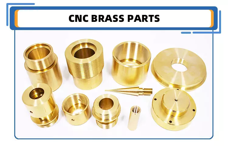
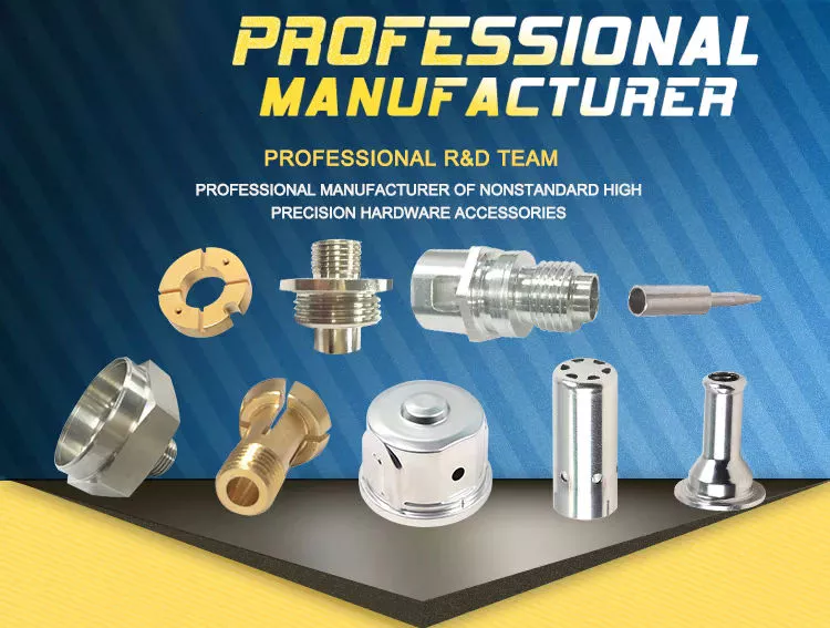
China OEM Customized CNC Aluminum Turned Forged Stamping Lathe Machined Tractor Guitar ATV Vehicle Valve Pump Boat Trailer Hydraulic Agricultural Industrial Parts agricultural spare parts

Product Description


Product display

Product description:
1-material:
Stainless steel:SS201,SS301,SS303,SS304,SS316,SS416 etc.
Iron:A36,45#,1213,12L14,1215 etc.
Aluminun:AL6061,AL6063,AL6082,AL7075,AL5052 etc.
Copper:C11000,C12000,C36000 etc.
Brass:HPb63,HPb62,HPb61,HPb59,H59,H62,H68,H80 etc.
Steel:mild steel,carbon steel,4140,4340,Q235,Q345B,20#,45# etc.
Plastic:ABS,PP,PEI,Peek,PE,POM,Delrin,Nylon,Teflon etc.

2-Parameter
3/4/5-axis CNCmilling,CNC Turning,dilling etc.
Precision:CNC turning ±0.003mm,CNC Milling ±0.01mm
Test equipment:Project,CMM,Altimeter,Micrometer,Thread Gages,Calipers,Pin Gauge etc.
Drawing Format:IGS,STP,X-T,DXF,Pro/E,PDFA
Workable size: CNC turning :φ0.5-φ300*750mm,CNC milling:510*1571*500mm(max).

3-Finishing:Chrome plating,Nickle plating,Tin plating,Zinc plating,Polishing,Anodizing,Power-coating,Oxide black.electroless nickel etc.

4-OEM&ODM are welcome.welcome to  processing by drawing and sample.we have powerful equipment to support the processing of products.The main equipment:Machining Center,CNC,Lathe,Turning machine,Milling machine,Drilling machine,Internal and external grinding machine,Cylindrical grinding machine,Tapping drilling machine,Wire cutting machine etc.
 
5-Delivery time:5-25days after the confirmation of sample(according to order quatity.)
   The mode of transportation:Express,by sea or by air(according to customer needs)
   Parking:carton/wooden box/other

12 years more experienced  engineers team and well trained sales team to support every project.We need long-term customers,excellent products quality and competitive price are our basic to achieve it.
why choose us?because we are professional.Place your order and we’ll take care of the rest.
Thank you.

US $1-65
/ Piece
|
5 Pieces

(Min. Order)

###

After-sales Service: Ensure That The Design Meets The Requirements
Warranty: Ensure That The Design Meets The Requirements
Application: Metal/Stainless Steel/Aluminum Alloy/Plastic/Other
Process Usage: Metal-Cutting CNC Machine Tools, CNC Non-Conventional Machine Tools, Metal-Forming CNC Machine Tools
Movement Method: Linear Control
Control Method: Closed-Loop Control

###

Samples:
US$ 50/Piece
1 Piece(Min.Order)

|
Request Sample

###

Customization:

Types of Ball Bearings

In their most basic form, Ball Bearings have one common feature – they are made of steel. The majority of these bearings are made of 52100 steel, which has one percent chromium and one percent carbon. The steel can be hardened by heat trea
tment. 440C stainless steel is used for rusting problems. A cage around the ball balls is traditionally made from thin steel. However, some bearings use molded plastic cages to save money and friction.
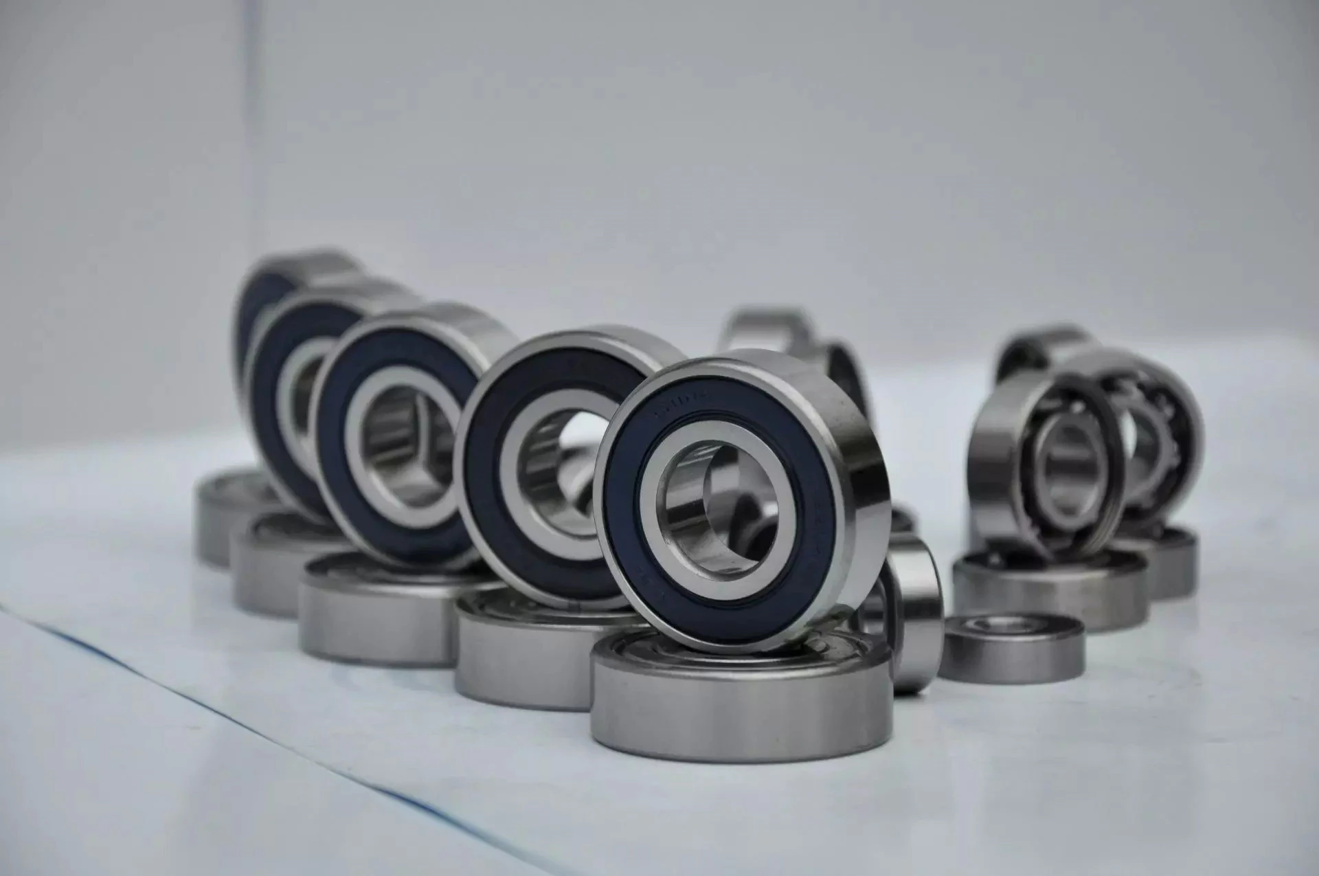
bearing

Single-row designs

Steel linear translation stages often use single-row designs for ball bearings. These types of bearings provide smooth linear travel and can withstand high loads. The material steel has a high modulus of elasticity and a high stiffness, as well as a lower thermal expansion than aluminum. For these reasons, steel is the material of choice for a ball bearing in a typical user environment. Single-row designs for ball bearings are also suitable for applications in humid or corrosive environments.
Single-row designs for ball bearings are available in a variety of sizes and are axially adjustable. They have a high radial capacity, but require relatively little space. Single-row deep groove ball bearings with snap rings are STN 02 4605 or R47, respectively. Bearings with snap rings are identified by a suffix such as NR. They may not have seals or shields installed.
These single-row angular contact ball bearings are capable of supporting axial and radial loads. In a two-raceway arrangement, the radial load on bearing A causes a radial load to act on bearing B. Both axial and radial forces are transmitted between single-row angular contact ball bearings, and the resulting internal force must be taken into account to calculate equivalent dynamic bearing loads P.
Single-row deep groove ball bearings are the most common type of ball bearings. These bearings are designed with only one row of rolling elements. The single-row design is simple and durable, which makes it ideal for high-speed applications. Single-row designs for ball bearings are also available in various bore sizes. They can also come in a variety of shapes and are non-separable. If you need a high-speed bearing, you may want to opt for a double-row design.
In addition to single-row designs for ball bearings, you can choose ceramic or steel ball bearings. Ceramic balls are considerably harder than steel balls, but they are not as hard as steel. Hence, ceramic bearings are stiffer than steel ball bearings, resulting in increased stress on the outer race groove and lower load capacity. This is a great benefit for those who need the bearings to be lightweight and strong.
The difference between single-row and double-row designs is in the way that the inner and outer ring are installed. A single-row design places the inner ring in an eccentric position relative to the outer ring. The two rings are in contact at one point, which causes a large gap in the bearing. The balls are then inserted through the gap. As a result, the balls are evenly distributed throughout the bearing, which forces the inner and outer rings to become concentric.
Deep-groove ball bearings are one of the most popular types of ball bearings. They are available in different designs, including snap-ring, seal and shield arrangements. The race diameter of a deep-groove ball bearing is close to the ball’s diameter. These types of bearings are suited for heavy loads, and their axial and radial support are excellent. Their main drawback is that the contact angle cannot be adjusted to accommodate a wide range of relative loads.
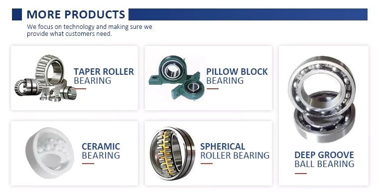
bearing

Ceramic hybrid ball bearings

Hybrid ball bearings with ceramic balls have numerous advantages. They feature improved kinematic behavior and require less lubrication. Consequently, they can reduce operating costs. Additionally, their low thermal expansion coefficient allows for smaller changes in contact angle and preload variations, and they can retain tolerances. Furthermore, ceramic hybrid ball bearings have significantly increased life spans compared to conventional steel-steel ball bearings, with up to 10 times the lifespan.
Although ceramic bearings can be used in automotive applications, many people believe that they’re a poor choice for bicycle hubs. They don’t reduce weight and only work well in high-rpm environments. As a result, many cyclists don’t even bother with ceramic-based bearings. However, both Paul Lew and Alan are of the opinion that ceramic bearings are best suited for industrial or medical equipment applications. Furthermore, Paul and Alan believe that they are ideal for high-altitude drone motors.
Another advantage of ceramic hybrid ball bearings is that they use less friction than conventional steel-based balls. They are also more durable, requiring less lubrication than steel-based bearings. Furthermore, the lower friction and rolling resistance associated with ceramic-based ball bearings means that they can last ten times longer than steel-based bearings. A ceramic-based hybrid ball bearing can be used for applications where speed and lubrication are critical.
Ceramic hybrid ball bearings feature both steel and silicon nitride balls. Silicon nitride balls have 50% more modulus of elasticity than steel balls and can improve accuracy and precision. Ceramic balls also have a smoother surface finish than steel balls, which reduces vibration and spindle deflection. These benefits result in increased speed and improved production quality. In addition to this, ceramic balls can also reduce the operating temperature, enhancing the work environment.
Hybrid bearings are a popular alternative to steel bearings. They have some benefits over traditional steel bearings, and are becoming a popular choice for engineered applications. Hybrid bearings are ideal for high speed machines. The material used to manufacture ceramic balls is a high-quality alloy, and is comparatively inexpensive. But you must understand that lubrication is still necessary for hybrid bearings. If you are not careful, you may end up wasting money.
These ball bearings can be used in many industries and applications, and they are widely compatible with most metals. The main advantage of hybrid ball bearings is that they are very durable. While steel balls tend to corrode and wear out, ceramic ball bearings can withstand these conditions while minimizing maintenance and replacement costs. The benefits of hybrid ball bearings are clear. So, consider switching to these newer types of ball bearings.
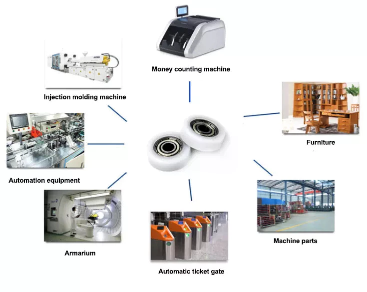
bearing

Self-aligning ball bearings

Self-aligning ball bearings are a good choice for many applications. They are a great alternative to traditional ball bearings, and they are ideal for rotating applications in which the shaft must move in several directions. They are also ideal for use in rotating parts where a tight tolerance is necessary. You can choose between two types: plain and flex shaft. Read on to find out which one will suit your needs.
Self-aligning ball bearings are designed with a higher axial load carrying capacity than single-row radial deep groove ball bearings. The amount of axial load carrying capacity is dependent upon the pressure angle. These bearings have a hollow raceway in the outer ring that allows the inner ring to pivot without friction. They are often used for high-speed applications. Because of their design, they are highly accurate.
Self-aligning ball bearings are radial bearings that feature two rows of balls in a spherical outer ring. They also feature two deep uninterrupted raceway grooves in the inner ring. Their unique features make them an excellent choice for applications where shaft deflection is a significant factor. Despite their small size, they have a high level of precision and can withstand heavy loads.
Self-aligning ball bearings can compensate for misalignment in shaft applications. The inner ring and ball assembly are positioned inside an outer ring containing a curved raceway. This spherical design allows the balls and cage to deflect and re-align around the bearing center. These bearings are also ideal for applications where shaft deflection is significant, such as in simple woodworking machinery.
Another type of self-aligning ball bearing uses a common concave outer race. Both balls and outer races automatically compensate for angular misalignment caused by machining, assembly, and deflections. Compared to spherical rollers, they have lower frictional losses than their spherical counterparts. Self-alignment ball bearings also have lower vibration levels compared to other types of bearings.
Self-aligning ball bearings operate in misaligned applications because their spherical outer raceway can accommodate misalignment. This design allows them to work in applications where shaft deflection or housing deformation is common. They are therefore more suitable for low to medium-sized loads. The only real drawback to self-aligning ball bearings is their price. If you need to purchase a self-aligning ball bearing for your next project, you can expect to pay around $1500.

China OEM Customized CNC Aluminum Turned Forged Stamping Lathe Machined Tractor Guitar ATV Vehicle Valve Pump Boat Trailer Hydraulic Agricultural Industrial Parts     agricultural spare partsChina OEM Customized CNC Aluminum Turned Forged Stamping Lathe Machined Tractor Guitar ATV Vehicle Valve Pump Boat Trailer Hydraulic Agricultural Industrial Parts     agricultural spare parts
editor by czh 2022-11-28
China high quality CZPT Tractor Hydraulic Pump F0nn600bb Tractor Parts near me supplier

Product Description

FORD Tractor Hydraulic Pump F0NN6
Ford Tractor: 5610, 5640, 6610, 6640, 6810, 7610, 7740, 7840, 8240, 8340

We also support CASE IH, FIAT, FORD, JOHNDEERE, KUBOTA, MF Tractor OEM Pumps, Steering units.

1. OEM quality.
2. Advantage price.
3. Fast delivery.
4. Warranty quality.
5. Support retail and wholesale.
6. Diversified payment methods.
 

Foed Tractor OEM Paump

D0NN6

D8NN6

D8NN6

E1NN6

D0NN6

D8NN6

E6NN3K514AB, 83960261

E6NN3K514EA, 87559440

D5NN6

E6NN3K514PA

E9NN6

82988360

We insist: nobody has, we have; somebody has, we have better.
We embrace: user is priority, quality is priority, service is priority.
We expect: share the fruit of development, create brilliant career, and serve the community together.
Elephant Fluid Power Co.,Ltd Company is willing to start a new journey with you hand in hand!

We are looking for good long business partner and friendship.
If you are interested in our products, please contact me.I’ll give you a favorable quotation.


The benefits of rubber bushings and how they work

If you have experienced increased vibration while driving, you know the importance of replacing the control arm bushings. The resulting metal-to-metal contact can cause annoying driving problems and be a threat to your safety. Over time, the control arm bushings begin to wear out, a process that can be exacerbated by harsh driving conditions and environmental factors. Additionally, larger tires that are more susceptible to bushing wear are also prone to increased vibration transfer, especially for vehicles with shorter sidewalls. Additionally, these plus-sized tires, which are designed to fit on larger rims, have a higher risk of transmitting vibrations through the bushings.
bushing

rubber

Rubber bushings are rubber tubes that are glued into the inner or outer curve of a cylindrical metal part. The rubber is made of polyurethane and is usually prestressed to avoid breaking during installation. In some cases, the material is also elastic, so it can slide. These properties make rubber bushings an integral part of a vehicle’s suspension system. Here are some benefits of rubber bushings and how they work.
Rubber bushings are used to isolate and reduce vibration caused by the movement of the 2 pieces of equipment. They are usually placed between 2 pieces of machinery, such as gears or balls. By preventing vibrations, rubber bushings improve machine function and service life. In addition to improving the overall performance of the machine, the rubber bushing reduces noise and protects the operator from injury. The rubber on the shock absorber also acts as a vibration isolator. It suppresses the energy produced when the 2 parts of the machine interact. They allow a small amount of movement but minimize vibration.
Both rubber and polyurethane bushings have their advantages and disadvantages. The former is the cheapest, but not as durable as polyurethane. Compared to polyurethane, rubber bushings are a better choice for daily commutes, especially long commutes. Polyurethane bushings provide better steering control and road feel than rubber, but can be more expensive than the former. So how do you choose between polyurethane and rubber bushings?

Polyurethane

Unlike rubber, polyurethane bushings resist high stress environments and normal cycling. This makes them an excellent choice for performance builds. However, there are some disadvantages to using polyurethane bushings. Read on to learn about the advantages and disadvantages of polyurethane bushings in suspension applications. Also, see if a polyurethane bushing is suitable for your vehicle.
Choosing the right bushing for your needs depends entirely on your budget and application. Softer bushings have the lowest performance but may have the lowest NVH. Polyurethane bushings, on the other hand, may be more articulated, but less articulated. Depending on your needs, you can choose a combination of features and tradeoffs. While these are good options for everyday use, for racing and hardcore handling applications, a softer option may be a better choice.
The initial hardness of the polyurethane bushing is higher than that of the rubber bushing. The difference between the 2 materials is determined by durometer testing. Polyurethane has a higher hardness than rubber because it does not react to load in the same way. The harder the rubber, the less elastic, and the higher the tear. This makes it an excellent choice for bushings in a variety of applications.

hard

Solid bushings replace the standard bushings on the subframe, eliminating axle clutter. New bushings raise the subframe by 0.59″ (15mm), correcting the roll center. Plus, they don’t create cabin noise. So you can install these bushings even when your vehicle is lowered. But you should consider some facts when installing solid casing. Read on to learn more about these casings.
The stiffest bushing material currently available is solid aluminum. This material hardly absorbs vibrations, but it is not recommended for everyday use. Its stiffness makes it ideal for rail vehicles. The aluminum housing is prone to wear and tear and may not be suitable for street use. However, the solid aluminum bushings provide the stiffest feel and chassis feedback. However, if you want the best performance in everyday driving, you should choose a polyurethane bushing. They have lower friction properties and eliminate binding.
Sturdy subframe bushings will provide more driver feedback. Additionally, it will strengthen the rear body, eliminating any movement caused by the subframe. You can see this structural integration on the M3 and M4 models. The benefits of solid subframe bushings are numerous. They will improve rear-end handling without compromising drivability. So if you plan to install a solid subframe bushing, be sure to choose a solid bushing.
bushing

Capacitor classification

In the circuit, there is a high electric field on both sides of the capacitor grading bushing. This is due to their capacitor cores. The dielectric properties of the primary insulating layer have a great influence on the electric field distribution within the bushing. This article discusses the advantages and disadvantages of capacitor grade bushings. This article discusses the advantages and disadvantages of grading bushings for capacitors in DC power systems.
One disadvantage of capacitor grading bushings is that they are not suitable for higher voltages. Capacitor grading bushings are prone to serious heating problems. This may reduce their long-term reliability. The main disadvantage of capacitor grading bushings is that they increase the radial thermal gradient of the main insulation. This can lead to dielectric breakdown.
Capacitor grading bushing adopts cylindrical structure, which can suppress the influence of temperature on electric field distribution. This reduces the coefficient of inhomogeneity of the electric field in the confinement layer. Capacitor grading bushings have a uniform electric field distribution across their primary insulation. Capacitive graded bushings are also more reliable than nonlinear bushings.
Electric field variation is the most important cause of failure. The electrode extension layer can be patterned to control the electric field to avoid flashover or partial discharge of the primary insulating material. This design can be incorporated into capacitor grading bushings to provide better electric fields in high voltage applications. This type of bushing is suitable for a wide range of applications. This article discusses the advantages and disadvantages of capacitor grade bushings.

Metal

When choosing between plastic and metal sleeves, it is important to choose a product that can handle the required load. Plastic bushings tend to deteriorate and often crack under heavy loads, reducing their mechanical strength and service life. Metal bushings, on the other hand, conduct heat more efficiently, preventing any damage to the mating surfaces. Plastic bushings can also be made with lubricating fillers added to a resin matrix.
Plastic bushings have many advantages over metal bushings, including being cheap and versatile. Plastic bushings are now used in many industries because they are inexpensive and quick to install. These plastic products are also self-lubricating and require less maintenance than metals. They are often used in applications where maintenance costs are high or parts are difficult to access. Also, if they are prone to wear and tear, they are easy to replace.
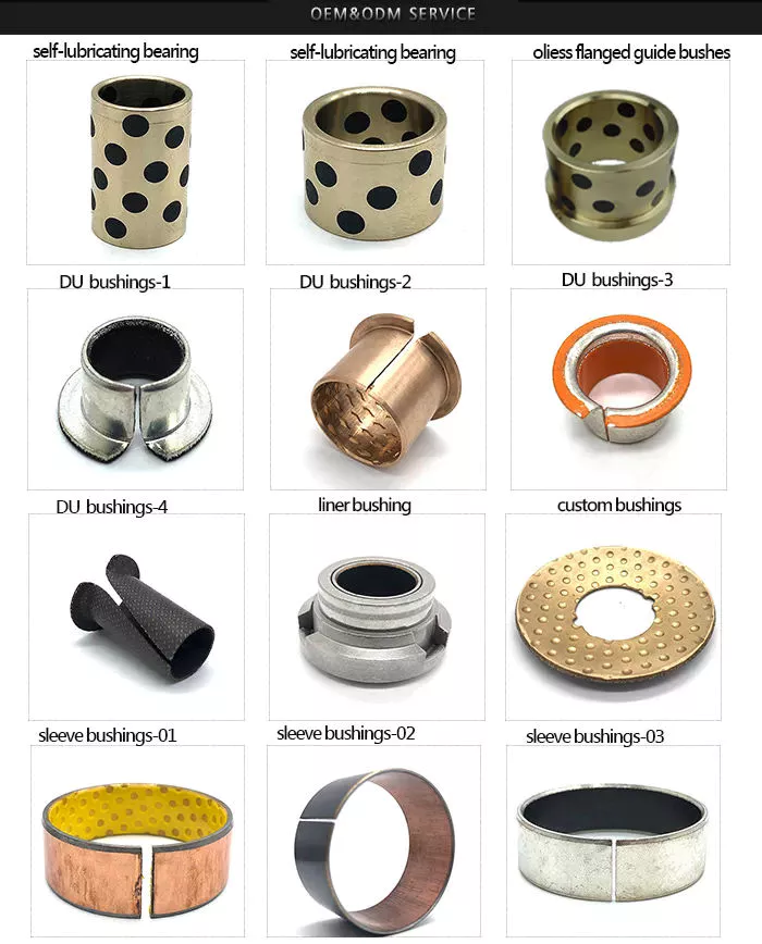
Metal bushings can be made of PTFE, plastic or bronze and are self-lubricating. Graphite plugs are also available for some metal bushings. Their high load capacity and excellent fatigue resistance make them a popular choice for automotive applications. The bi-metallic sintered bronze layer in these products provides excellent load-carrying capacity and good friction properties. The steel backing also helps reduce processing time and avoids the need for additional pre-lubrication.
bushing

plastic

A plastic bushing is a small ball of material that is screwed onto a nut or locknut on a mechanical assembly. Plastic bushings are very durable and have a low coefficient of friction, making them a better choice for durable parts. Since they do not require lubrication, they last longer and cost less than their metal counterparts. Unlike metal bushings, plastic bushings also don’t scratch or attract dirt.
One type of acetal sleeve is called SF-2. It is made of metal alloy, cold rolled steel and bronze spherical powder. A small amount of surface plastic penetrated into the voids of the copper spherical powder. Plastic bushings are available in a variety of colors, depending on the intended application. SF-2 is available in black or grey RAL 7040. Its d1 diameter is sufficient for most applications.
Another acetal sleeve is UHMW-PE. This material is used in the production of bearings and in low load applications. This material can withstand pressures from 500 to 800 PSI and is widely available. It is also self-lubricating and readily available. Due to its high resistance to temperature and chemical agents, it is an excellent choice for low-load industrial applications. If you’re in the market for an alternative to nylon, consider acetal.
Positional tolerances in many automotive components can cause misalignment. Misaligned plastic bushings can negatively impact the driver’s experience. For example, the cross tubes used to mount the seat to the frame are made by a stamping process. The result is a misalignment that can increase torque. Also, the plastic bushing is pushed to 1 side of the shaft. The increased pressure results in higher friction, which ultimately results in a poor driving experience.
v
China high quality CZPT Tractor Hydraulic Pump F0nn600bb Tractor Parts     near me supplier China high quality CZPT Tractor Hydraulic Pump F0nn600bb Tractor Parts     near me supplier

China high quality Hydraulic Pump Re223233 Deere Tractor Parts with Free Design Custom

Product Description

Hydraulic pump RE223233 Deere Tractor Parts

Replaces Deere: RE223233
Deere : 5045D, 5045E, 5055E, 5065E, 5065M, 5075E, 5103, 5203, 5204, 5303, 5310, 5403, 5410, 5610

1. OEM quality.
2. Advantage price.
3. Fast delivery.
4. Warranty quality.
5. Support retail and wholesale.
6. Diversified payment methods.


Deere Tractor OEM Paump

RE68886 , RE57445

AZ19692,

RE223233

AR103033, AR103036

RE73947, RE72058

AL156335, AL117812

RE241577 ,RE241578

We also support CASE IH, FIAT, FORD, DEERE, KUBOTA, MF Tractor OEM Pumps, Steering units.

We insist: nobody has, we have; somebody has, we have better.
We embrace: user is priority, quality is priority, service is priority.
We expect: share the fruit of development, create brilliant career, and serve the community together.
Elephant Fluid Power Co.,Ltd Company is willing to start a new journey with you hand in hand!

We are looking for good long business partner and friendship.
If you are interested in our products, please contact me.I’ll give you a favorable quotation.


Types of pulleys and their advantages and disadvantages

There are several types of pulleys. Learn the basic equations of the pulley system. Then learn about the different uses for pulleys. The disadvantages of using pulleys will be covered. Knowing these, you can buy the pulley that suits your needs. Here are some of the best pulley types and their pros and cons.
pulley

Basic equations of pulley systems

A pulley system is a mechanism that allows 2 blocks of a certain mass to be connected by a taut rope. The acceleration of each block is the same in magnitude and direction. The external force acting on each block is the weight of the block (10g) and the tension in the string. The tension between the 2 blocks is the total tension and the force acting on the pulley is the weight of the 2 blocks.
This simple mechanism uses 2 simple equations to explain how the system works. First, the mass of the weight on both sides of the pulley must be the same. When the weight is forced to move, the rope tightens and the second pulley descends. The weight is also attached to the second pulley and must be the same distance as the first pulley. This will result in a speed ratio of 2 times the distance covered by the first pulley.
Second, we have to calculate the force required to lift the object. The lower mass is supported by a wire configuration passing through all pulleys, while the uppermost pulley is used to apply the force. The lower block is used to support the weight. The applied force needs to travel a distance nx to move the weight. This distance, called MA, can be written as:
Once we have gathered the necessary information, we can apply the calculations to the pulley system. We can also use the Mechanical Advantage Calculator to calculate the force on the anchor. To do this, we must apply a force to the load as well as to the pulley itself. Using this equation, we can calculate the force required by the load to lift the load.
pulley

Types of pulleys

There are 3 basic types of pulleys: movable, fixed and compound. Both types of pulleys translate the force applied to them. The ideal mechanical advantage of pulleys is two. This is because a single movable pulley only doubles the force, whereas a compound pulley doubles or triples the force. This type of pulley is often used with other types of pulleys.
Movable pulls move with the weight of the load, and the force pulling them increases on the lift side. They are often found in utility elevators and construction cranes. These systems are very simple, inexpensive and quiet to use. The force required to lift the object depends on the mechanical advantage of the system. The 2 most common types of pulleys are listed below. Let’s take a closer look at each one.
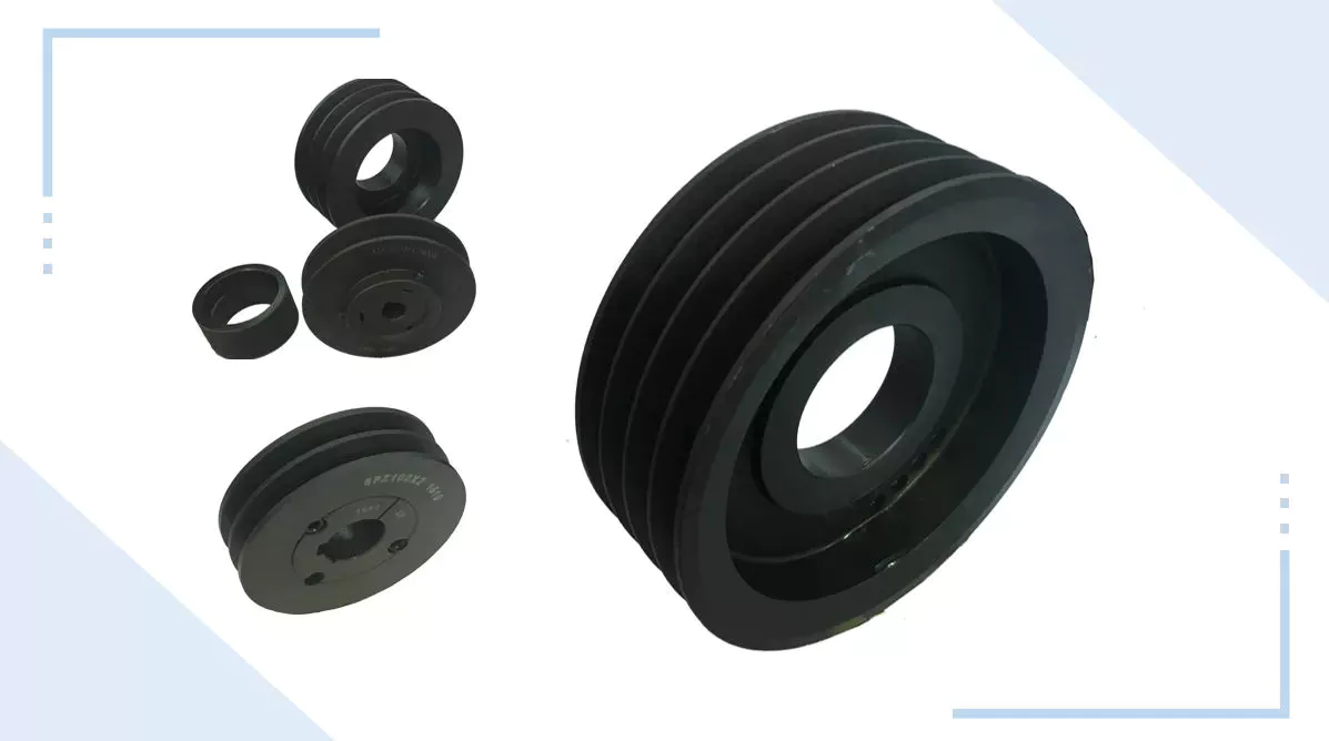
V-shaped pulleys are used in vehicles and electric motors. These pulleys require a “V” belt to function properly. Some have multiple “V” grooves to avoid slipping. They are used in heavy duty applications to reduce the risk of power slip. These pulleys also have more than 1 “V” groove. V-belt pulleys are commonly used in vehicles and electric motors.
Composite pulleys are made from more than 1 type of cable or rope wrapped around the wheel. They can be fixed or hinged and are usually made of stainless steel or bronze. Composite pulleys have multiple layers and can be a single unit or many different components. There are 3 main types of pulleys: fixed pulleys and composite pulleys. These are the most common types. Almost every type of pulley is used for some type of application.
Fixed pulleys have 1 advantage over movable pulleys: they change direction as the weight of the load increases. They are typically used in heavy construction equipment. Gun tackles, patio tackles, and stationary tackles are examples of equipment that use a pulley mechanism. These devices are very common and can be found on most modern construction sites. They provide great convenience for lifting large loads.

application

What are the applications of pulleys? Simply put, a pulley is a mechanical device that transforms a difficult task into an easier one. It consists of ropes and pulleys. It is usually used to lift objects. Usually, people wrap a rope around a pulley and pull up to lift the object. One disadvantage of using pulleys is that they require the same force as lifting the object directly.
One of the most popular applications of pulleys is lifting heavy objects. They help people pull up heavy objects and blocks. The system can also be used in seeders, lifts, grinders, etc. Other applications include raising flags, loading cargo, pulling curtains and rock or mountain climbing. Students can learn about the various uses of pulleys and the physics behind them.
Pulleys can be made of many different materials, depending on the application. Some are movable, which means they move with the object they are used to lift. This pulley system can be made of nylon, wire rope or fiber material. The best part about these systems is that they are easy to install and maintain. For a better grasp, use the guide or video tutorial to learn more about the pulley system and how it works.
Tapered pulleys are common in paper mills. They are high-quality pulleys that transmit power to connected parts. They can be dynamic or static and have different balances. Because pulley systems are highly customized, most industrial applications require systems designed specifically for specific applications. In this way, the system is safe, simple and inexpensive. The benefits of this design are endless.
The most common use of pulleys is for motor drives. They are used to minimize noise by applying force to the shaft to reduce the workload. They are also less expensive than gears and do not require lubrication. Furthermore, they can change the direction of the applied force. They are also less expensive than gears and are often used with other components. A screw is a cylindrical member with helical ribs used to connect something.
pulley

shortcoming

Although the pulley system makes it easier to move heavy objects, it still has some drawbacks. When using a pulley system, you must remember that the force required to lift the weight increases with the number of cycles. In addition, the distance between the puller and the heavy object increases, which may lead to accidents. Also, moving heavy objects can be tricky if the rope slips. Pulley systems are not very expensive and can be easily assembled. However, it does require a lot of space.
First, it is not efficient. Besides being inefficient, pulleys produce different forces at different speeds. Fixed pulleys use more force than the load, while movable pulleys move with the load. A movable pulley requires less force than a fixed pulley, but the combined system travels a long distance. Therefore, this method is not as efficient as the fixed method.
Pulleys are not only used in industrial processes. You can see them in various places in your daily life. For example, large construction cranes use pulleys to lift heavy loads. Even flagpoles, blinds, clotheslines, ziplines, motors and climbing equipment use pulleys. Still, despite their advantages, the disadvantages are not too serious.
Another disadvantage of the pulley is its wear and tear. While a pulley’s housing is theoretically infinite, its bearings and locking components typically wear out over time. To overcome this problem, a new bearing and locking assembly can be installed. No need to replace the housing and shaft, the entire assembly can be re-bonded and painted to replicate the original look. Alternatively, the pulley can be replaced with a new housing and shaft.
Using pulleys can also reduce the advantage of pulleys. On the other hand, interception and tackle is a system in which 2 pulleys are connected to each other using ropes. Unlike pulleys, pulley pulley systems can be adjusted in the direction of travel and can move heavy loads up to 4 times their force when used in hydraulic lifts.

China high quality Hydraulic Pump Re223233 Deere Tractor Parts     with Free Design CustomChina high quality Hydraulic Pump Re223233 Deere Tractor Parts     with Free Design Custom

China Standard Shenzhen OEM Customized CNC Aluminum Turned Forged Stamping Lathe Machined Tractor ATV/UTV Vehicle Valve Pump Trailer Hydraulic Agricultural Industrial Parts with Best Sales

Product Description

                                                                 A Letter to Our Future Partners
Dear,

Plz wait don’t scroll. No doubt, that partner is you! Thank you for visiting our Xielifeng CNC machining service at MIC now.

Xielifeng Tech is located in HangZhou, China, which focuses on CNC machining, including milling, turning, auto-lathe, die casting. Both metal and plastic material are within our capability. We provide one-stop service, from professional design analysis, to free quote, fast prototype, ISO standard manufacturing, to safe shipping and great after-sales services.

 During these years, we have win lots of trust in the global market, most of them come from North America and Europe. Now you may have steady suppliers, but still hope you can keep us in the archives to get more market news.

More interests, feel free to send us an inquiry via Contact now, or directly to our email, and then our professional sales manager will get back to you ASAP!

Warmly regards.
Peter Tu (Sales Manager)


Service Custom CNC Machining Parts of Most Materials
Quotation According to your drawing(size, material, thickness, processing content, and required technology, etc)
Tolerance & Surface Roughness +/-0.005 – 0.1mm & Ra0.2 – Ra3.2 (Customize available)
Materials Available Aluminum, Copper, Stainless steel, Iron, PE, PVC, ABS, etc.
Surface Treatment Polishing, general/hard/color oxidation, surface chamfering, tempering, etc.
Processing CNC Turning, Milling, Drilling, Auto Lathe, Tapping, Bushing, Surface Treatment, etc.
Payment method Our business face global. and support credit cards, T/T, L/C, Paypal, etc.
Drawing Formats PRO/E, Auto CAD, Solid Works , UG, CAD / CAM / CAE, PDF

FAQ: 

Q1: Where can I get product&price information?
A1: Send us an inquiry in this page or e-mail, we will contact you after upon receipt of your mail.

Q2: How soon can I get samples and how much the fee?
A2: Depending on your specific project, it usually takes 10 to 20 days. the fee depends on the product drawing, and the fee will be returned to your bulk order.

Q3: How to enjoy the OEM services?
A3: Usually, base on your design drawings or original samples, we give some technical proposals and a quotation to you, after your agreement, we produce for you.

Q4: Can you make machining parts based on our samples?
A4: Yes, we can make measurements based on your samples to make drawings for machining parts making.

Q5: Is it possible to know how are my products going on without visiting your company?
A5: We will offer a detailed production schedule and send weekly reports with digital pictures and videos which show the machining progress.

Q6: Will my drawing safe after you get it?
A6: Yes, we can sign the NDA before got your drawing.

Synthesis of Epicyclic Gear Trains for Automotive Automatic Transmissions

In this article, we will discuss the synthesis of epicyclic gear trains for automotive automatic transmissions, their applications, and cost. After you have finished reading, you may want to do some research on the technology yourself. Here are some links to further reading on this topic. They also include an application in hybrid vehicle transmissions. Let’s look at the basic concepts of epicyclic gear trains. They are highly efficient and are a promising alternative to conventional gearing systems.
Gear

Synthesis of epicyclic gear trains for automotive automatic transmissions

The main purpose of automotive automatic transmissions is to maintain engine-drive wheel balance. The kinematic structure of epicyclic gear trains (EGTs) is derived from graph representations of these gear trains. The synthesis process is based on an algorithm that generates admissible epicyclic gear trains with up to 10 links. This algorithm enables designers to design auto gear trains that have higher performance and better engine-drive wheel balance.
In this paper, we present a MATLAB optimization technique for determining the gear ratios of epicyclic transmission mechanisms. We also enumerate the number of teeth for all gears. Then, we estimate the overall velocity ratios of the obtained EGTs. Then, we analyze the feasibility of the proposed epicyclic gear trains for automotive automatic transmissions by comparing their structural characteristics.
A six-link epicyclic gear train is depicted in the following functional diagram. Each link is represented by a double-bicolor graph. The numbers on the graph represent the corresponding links. Each link has multiple joints. This makes it possible for a user to generate different configurations for each EGT. The numbers on the different graphs have different meanings, and the same applies to the double-bicolor figure.
In the next chapter of this article, we discuss the synthesis of epicyclic gear trains for automotive automatic transaxles. SAE International is an international organization of engineers and technical experts with core competencies in aerospace and automotive. Its charitable arm, the SAE Foundation, supports many programs and initiatives. These include the Collegiate Design Series and A World In Motion(r) and the SAE Foundation’s A World in Motion(r) award.
Gear

Applications

The epicyclic gear system is a type of planetary gear train. It can achieve a great speed reduction in a small space. In cars, epicyclic gear trains are often used for the automatic transmission. These gear trains are also useful in hoists and pulley blocks. They have many applications in both mechanical and electrical engineering. They can be used for high-speed transmission and require less space than other types of gear trains.
The advantages of an epicyclic gear train include its compact structure, low weight, and high power density. However, they are not without disadvantages. Gear losses in epicyclic gear trains are a result of friction between gear tooth surfaces, churning of lubricating oil, and the friction between shaft support bearings and sprockets. This loss of power is called latent power, and previous research has demonstrated that this loss is tremendous.
The epicyclic gear train is commonly used for high-speed transmissions, but it also has a small footprint and is suitable for a variety of applications. It is used as differential gears in speed frames, to drive bobbins, and for the Roper positive let-off in looms. In addition, it is easy to fabricate, making it an excellent choice for a variety of industrial settings.
Another example of an epicyclic gear train is the planetary gear train. It consists of 2 gears with a ring in the middle and the sun gear in the outer ring. Each gear is mounted so that its center rotates around the ring of the other gear. The planet gear and sun gear are designed so that their pitch circles do not slip and are in sync. The planet gear has a point on the pitch circle that traces the epicycloid curve.
This gear system also offers a lower MTTR than other types of planetary gears. The main disadvantage of these gear sets is the large number of bearings they need to run. Moreover, planetary gears are more maintenance-intensive than parallel shaft gears. This makes them more difficult to monitor and repair. The MTTR is also lower compared to parallel shaft gears. They can also be a little off on their axis, causing them to misalign or lose their efficiency.
Another example of an epicyclic gear train is the differential gear box of an automobile. These gears are used in wrist watches, lathe machines, and automotives to transmit power. In addition, they are used in many other applications, including in aircrafts. They are quiet and durable, making them an excellent choice for many applications. They are used in transmission, textile machines, and even aerospace. A pitch point is the path between 2 teeth in a gear set. The axial pitch of 1 gear can be increased by increasing its base circle.
An epicyclic gear is also known as an involute gear. The number of teeth in each gear determines its rate of rotation. A 24-tooth sun gear produces an N-tooth planet gear with a ratio of 3/2. A 24-tooth sun gear equals a -3/2 planet gear ratio. Consequently, the epicyclic gear system provides high torque for driving wheels. However, this gear train is not widely used in vehicles.
Gear

Cost

The cost of epicyclic gearing is lower when they are tooled rather than manufactured on a normal N/C milling machine. The epicyclic carriers should be manufactured in a casting and tooled using a single-purpose machine that has multiple cutters to cut the material simultaneously. This approach is widely used for industrial applications and is particularly useful in the automotive sector. The benefits of a well-made epicyclic gear transmission are numerous.
An example of this is the planetary arrangement where the planets orbit the sun while rotating on its shaft. The resulting speed of each gear depends on the number of teeth and the speed of the carrier. Epicyclic gears can be tricky to calculate relative speeds, as they must figure out the relative speed of the sun and the planet. The fixed sun is not at zero RPM at mesh, so the relative speed must be calculated.
In order to determine the mesh power transmission, epicyclic gears must be designed to be able to “float.” If the tangential load is too low, there will be less load sharing. An epicyclic gear must be able to allow “float.” It should also allow for some tangential load and pitch-line velocities. The higher these factors, the more efficient the gear set will be.
An epicyclic gear train consists of 2 or more spur gears placed circumferentially. These gears are arranged so that the planet gear rolls inside the pitch circle of the fixed outer gear ring. This curve is called a hypocycloid. An epicyclic gear train with a planet engaging a sun gear is called a planetary gear train. The sun gear is fixed, while the planet gear is driven.
An epicyclic gear train contains several meshes. Each gear has a different number of meshes, which translates into RPM. The epicyclic gear can increase the load application frequency by translating input torque into the meshes. The epicyclic gear train consists of 3 gears, the sun, planet, and ring. The sun gear is the center gear, while the planets orbit the sun. The ring gear has several teeth, which increases the gear speed.
Another type of epicyclic gear is the planetary gearbox. This gear box has multiple toothed wheels rotating around a central shaft. Its low-profile design makes it a popular choice for space-constrained applications. This gearbox type is used in automatic transmissions. In addition, it is used for many industrial uses involving electric gear motors. The type of gearbox you use will depend on the speed and torque of the input and output shafts.

China Standard Shenzhen OEM Customized CNC Aluminum Turned Forged Stamping Lathe Machined Tractor ATV/UTV Vehicle Valve Pump Trailer Hydraulic Agricultural Industrial Parts     with Best SalesChina Standard Shenzhen OEM Customized CNC Aluminum Turned Forged Stamping Lathe Machined Tractor ATV/UTV Vehicle Valve Pump Trailer Hydraulic Agricultural Industrial Parts     with Best Sales

China Custom Good Price 14670-97310 Big Shaft 1467097310 High Pressure Tractor Power Steering Pump Nissan Spare Parts for Bus with Great quality

Product Description


GREEN Hydraulic
 is 1 strength Professional enterprise which integrates in Hydraulic Component with more than 15 years experience focusing on the abroad and Domestic Market. Our products including Piston Pump, Vane Pump, Gear Pump, Hydraulic Valve, Hydraulic Motor, Electric Motor, Oil Cooler, Accumulator and other hydraulic accessories etc. GREEN Hydraulic Piston Pump Series including CY, A2F, A2FO, A7V, A4V, A10V Series, which is the same as Orignal Rexroth, the same appreance, mounting size and working perofrmance. The products are widely used in machine tool, forging machinery, metallurgy machinery, engineering machinery, mine machinery and other hydraulic systems. They also can be used as hydraulic motors if the valve plate is changed into motor type. GREEN also supply replacement parts for Komatsu, Rexroth, Sauer, Hitachi, Catpillar, KYB, Kawasaki, Toshiba, Linde, Vickers, Yuekn, Nachi…Please consult online customer service for more models

Calculate the ideal mechanical advantage of pulleys

The basic equations for pulleys can be found in this article. It will also cover the different types of pulleys, the ideal mechanical advantages of pulleys, and some common uses of pulley systems. Read on to learn more! After all, a pulley is a simple mechanical device that changes the direction of a force. Learn more about pulleys and their common uses in engineering.
pulley

pulley basic equation

Pulleys work the same way as gravity, so they should withstand similar forces. Newton’s laws of motion can be used to calculate the forces in a pulley system. The second law of motion applies to forces and accelerations. Similar to this is Newton’s third law, which states that the directions of forces are equal and opposite. The fourth law dictates the direction of force. The Fifth Law states that tension is in equilibrium with gravity.
A pulley is a simple mechanism that transmits force by changing direction. They are generally considered to have negligible mass and friction, but this is only an approximation. Pulleys have different uses, from sailboats to farms and large construction cranes. In fact, they are the most versatile mechanisms in any system. Some of their most common applications and equations are listed below.
For example, consider 2 masses m. Those of mass m will be connected by pulleys. The static friction coefficient of the left stop is ms1, and the static friction coefficient of the right stop is ms2. A no-slip equation will contain multiple inequalities. If the 2 blocks are considered to be connected by a pulley, the coefficient of kinetic friction is mk. In other words, the weight of each block carries the same mass, but in the opposite direction.

Types of pulleys

A pulley is a device used to pull and push objects. Pulley systems are ropes, cables, belts or chains. The “drive pulley” is attached to the shaft and moves the driven pulley. They are available in a variety of sizes, and the larger they are, the higher the speed of power transmission. Alternatively, use small pulleys for smaller applications.
Two-wheel pulleys have 2 mechanical advantages. The greater the mechanical advantage, the less force is required to move the object. More wheels lift more weight, but smaller pulleys require less force. In a two-wheel pulley system, the rope is wound around 2 axles and a fixed surface. As you pull on the rope, the shafts above slowly come together.
Compound pulleys have 2 or more rope segments that are pulled up on the load. The mechanical advantage of compound pulleys depends on the number of rope segments and how they are arranged. This type of pulley can increase the force by changing the direction of the rope segment. There are 2 main types of pulleys. Composite pulleys are most commonly used in construction. The ideal mechanical advantage of pulleys is 2 or more.
Construction pulleys are a basic type. They are usually attached to wheel rails and can be lifted to great heights. Combinations of axes are also common. Construction pulleys can be raised to great heights to access materials or equipment. When used in construction, these pulleys are usually made of heavy materials such as wood or metal. They are secured with ropes or chains.

The ideal mechanical advantage of pulleys

The pulley system is a highly complex system with high mechanical advantages. Use a single pulley system to reduce the force required to lift an object by cutting it in half. The mechanical advantage increases as you add more pulleys, such as 6 or seven. To calculate the mechanical advantage of a pulley system, you need to count the number of rope segments between the pulleys. If the free end of the rope is facing down, don’t count it. If it’s facing up, count. Once you have your number, add it up.
The required mechanical advantage of a pulley is the number of rope segments it has to pull the load. The more rope segments, the lower the force. Therefore, the more rope segments the pulley has, the lower the force. If the rope segments are four, then the ideal mechanical advantage is four. In this case, the composite pulley quadrupled the load force.
The ideal mechanical advantage of a pulley system is the sum of the mechanical force and the force required to lift the load at its output. Typically, a single pulley system uses 2 ropes, and the mechanical force required to lift the load is multiplied by the 2 ropes. For a multi-pulley system, the number of ropes will vary, but the total energy requirement will remain the same. The friction between the rope and pulley increases the force and energy required to lift the load, so the mechanical advantage diminishes over time.
pulley

Common uses of pulley systems

A pulley system is a simple mechanical device typically used to lift heavy objects. It consists of a rotating wheel attached to a fixed shaft and a rope attached to it. When the wheel moves, the force applied by the operator is multiplied by the speed of the pulley, and the force is multiplied by the weight of the object being lifted. Common uses for pulley systems include pulling, lifting, and moving heavy objects.
The oil and petroleum industries use pulley systems in a variety of applications. Most commonly, pulleys are used in drilling operations and they are installed on top of the rig to guide the cable. The cable itself is attached to 2 pulleys suspended in the derrick, where they provide mechanical energy to the cable. Using a pulley system in this application provides the force needed to move the cable safely and smoothly.
The main advantage of the pulley system is that it minimizes the force required to lift an object. The force used to lift the object is multiplied by the desired mechanical advantage. The more rope segments, the lower the force required. On the other hand, a compound pulley system can have many segments. Therefore, a compound pulley system can increase the force a worker can exert on an object.
Safety Precautions to Take When Working on Pulley Systems

There are many safety precautions that should be observed when working on a pulley system. The first is to wear proper protective gear. This includes hard hats that protect you from falling objects. Also, gloves may be required. You should limit the amount of movement in the penalty area, and you should also keep the area free of unnecessary people and objects. Also, remember to wear a hard hat when working on the pulley system.
Another important safety precaution when working on a pulley system is to check the Safe Working Load (SWL) of the pulley before attaching anything. This will help you understand the maximum weight the pulley can hold. Also, consider the angle and height of the pulley system. Always use safety anchors and always remember to wear a hat when working on a pulley system.
Safe use of chain hoists requires training and experience. It is important to read the manufacturer’s manual and follow all safety precautions. If you’re not sure, you can actually inspect the hoist and look for signs of damage or tampering. Look for certifications for sprocket sets and other lifting accessories. Look for the Safe Working Load (SWL) marking on the chain hoist.
pulley

Example of a pulley system

Pulley systems are often used to lift items. It allows you to reduce the effort to lift and move the load by applying force in 1 direction. Pulley systems can be built and modeled to fit any type of project. This resource focuses on pulley systems and is designed to support the new GCSEs in Engineering, Design and Technology. There are also many examples of pulley systems suitable for various applications.
In the study, participants who read easy text took longer to manipulate the pulley system than those who read challenging text. In general, this suggests that participants with prior scientific experience used their cognitive abilities more effectively. Additionally, students who read simple texts spent less time planning the pulley system and more time on other tasks. However, the study did show that the time required to plan the pulley system was similar between the 2 groups.
In everyday life, pulley systems are used to lift various objects. Flagpoles are 1 of many pulley systems used to raise and lower flagpoles. They can also be used to raise and lower garage doors. Likewise, rock climbers use pulleys to help them ascend and descend. The pulley system can also be used to extend the ladder.

China Custom Good Price 14670-97310 Big Shaft 1467097310 High Pressure Tractor Power Steering Pump Nissan Spare Parts for Bus     with Great qualityChina Custom Good Price 14670-97310 Big Shaft 1467097310 High Pressure Tractor Power Steering Pump Nissan Spare Parts for Bus     with Great quality

China Good quality Customized CNC Aluminum Machining Parts of Motor Precision Tractor Valve Pump Vehicle Heavy Truck Support with Best Sales

Product Description

Factory Equipment:
Sample Exhibition:

Our Commitment:

  1. Advanced processing equipment
  2. All-round processing technology
  3. Timely delivery of precision machined parts
  4. Meet customer requirements
  5. To provide customers with defect-free parts

The custom machining services that we can offer:

  1. CNC Machining
  2. Casting
  3. Fabrication
  4. Turning
  5. Milling
  6. Stamping
  7. Forging
  8. Welding

We are committed to ensure to complete your custom projects as below:

  1. Within the timeframe
  2. Within the budget
  3. Meeting the quality standard

We can design and make precision parts according to customers’ samples, drawing and AutoCAD or Pro/E file.
Company Qualification:

Types of pulleys and their advantages and disadvantages

There are several types of pulleys. Learn the basic equations of the pulley system. Then learn about the different uses for pulleys. The disadvantages of using pulleys will be covered. Knowing these, you can buy the pulley that suits your needs. Here are some of the best pulley types and their pros and cons.
pulley

Basic equations of pulley systems

A pulley system is a mechanism that allows 2 blocks of a certain mass to be connected by a taut rope. The acceleration of each block is the same in magnitude and direction. The external force acting on each block is the weight of the block (10g) and the tension in the string. The tension between the 2 blocks is the total tension and the force acting on the pulley is the weight of the 2 blocks.
This simple mechanism uses 2 simple equations to explain how the system works. First, the mass of the weight on both sides of the pulley must be the same. When the weight is forced to move, the rope tightens and the second pulley descends. The weight is also attached to the second pulley and must be the same distance as the first pulley. This will result in a speed ratio of 2 times the distance covered by the first pulley.
Second, we have to calculate the force required to lift the object. The lower mass is supported by a wire configuration passing through all pulleys, while the uppermost pulley is used to apply the force. The lower block is used to support the weight. The applied force needs to travel a distance nx to move the weight. This distance, called MA, can be written as:
Once we have gathered the necessary information, we can apply the calculations to the pulley system. We can also use the Mechanical Advantage Calculator to calculate the force on the anchor. To do this, we must apply a force to the load as well as to the pulley itself. Using this equation, we can calculate the force required by the load to lift the load.
pulley

Types of pulleys

There are 3 basic types of pulleys: movable, fixed and compound. Both types of pulleys translate the force applied to them. The ideal mechanical advantage of pulleys is two. This is because a single movable pulley only doubles the force, whereas a compound pulley doubles or triples the force. This type of pulley is often used with other types of pulleys.
Movable pulls move with the weight of the load, and the force pulling them increases on the lift side. They are often found in utility elevators and construction cranes. These systems are very simple, inexpensive and quiet to use. The force required to lift the object depends on the mechanical advantage of the system. The 2 most common types of pulleys are listed below. Let’s take a closer look at each one.
V-shaped pulleys are used in vehicles and electric motors. These pulleys require a “V” belt to function properly. Some have multiple “V” grooves to avoid slipping. They are used in heavy duty applications to reduce the risk of power slip. These pulleys also have more than 1 “V” groove. V-belt pulleys are commonly used in vehicles and electric motors.
Composite pulleys are made from more than 1 type of cable or rope wrapped around the wheel. They can be fixed or hinged and are usually made of stainless steel or bronze. Composite pulleys have multiple layers and can be a single unit or many different components. There are 3 main types of pulleys: fixed pulleys and composite pulleys. These are the most common types. Almost every type of pulley is used for some type of application.
Fixed pulleys have 1 advantage over movable pulleys: they change direction as the weight of the load increases. They are typically used in heavy construction equipment. Gun tackles, patio tackles, and stationary tackles are examples of equipment that use a pulley mechanism. These devices are very common and can be found on most modern construction sites. They provide great convenience for lifting large loads.

application

What are the applications of pulleys? Simply put, a pulley is a mechanical device that transforms a difficult task into an easier one. It consists of ropes and pulleys. It is usually used to lift objects. Usually, people wrap a rope around a pulley and pull up to lift the object. One disadvantage of using pulleys is that they require the same force as lifting the object directly.
One of the most popular applications of pulleys is lifting heavy objects. They help people pull up heavy objects and blocks. The system can also be used in seeders, lifts, grinders, etc. Other applications include raising flags, loading cargo, pulling curtains and rock or mountain climbing. Students can learn about the various uses of pulleys and the physics behind them.
Pulleys can be made of many different materials, depending on the application. Some are movable, which means they move with the object they are used to lift. This pulley system can be made of nylon, wire rope or fiber material. The best part about these systems is that they are easy to install and maintain. For a better grasp, use the guide or video tutorial to learn more about the pulley system and how it works.
Tapered pulleys are common in paper mills. They are high-quality pulleys that transmit power to connected parts. They can be dynamic or static and have different balances. Because pulley systems are highly customized, most industrial applications require systems designed specifically for specific applications. In this way, the system is safe, simple and inexpensive. The benefits of this design are endless.
The most common use of pulleys is for motor drives. They are used to minimize noise by applying force to the shaft to reduce the workload. They are also less expensive than gears and do not require lubrication. Furthermore, they can change the direction of the applied force. They are also less expensive than gears and are often used with other components. A screw is a cylindrical member with helical ribs used to connect something.
pulley

shortcoming

Although the pulley system makes it easier to move heavy objects, it still has some drawbacks. When using a pulley system, you must remember that the force required to lift the weight increases with the number of cycles. In addition, the distance between the puller and the heavy object increases, which may lead to accidents. Also, moving heavy objects can be tricky if the rope slips. Pulley systems are not very expensive and can be easily assembled. However, it does require a lot of space.
First, it is not efficient. Besides being inefficient, pulleys produce different forces at different speeds. Fixed pulleys use more force than the load, while movable pulleys move with the load. A movable pulley requires less force than a fixed pulley, but the combined system travels a long distance. Therefore, this method is not as efficient as the fixed method.
Pulleys are not only used in industrial processes. You can see them in various places in your daily life. For example, large construction cranes use pulleys to lift heavy loads. Even flagpoles, blinds, clotheslines, ziplines, motors and climbing equipment use pulleys. Still, despite their advantages, the disadvantages are not too serious.
Another disadvantage of the pulley is its wear and tear. While a pulley’s housing is theoretically infinite, its bearings and locking components typically wear out over time. To overcome this problem, a new bearing and locking assembly can be installed. No need to replace the housing and shaft, the entire assembly can be re-bonded and painted to replicate the original look. Alternatively, the pulley can be replaced with a new housing and shaft.
Using pulleys can also reduce the advantage of pulleys. On the other hand, interception and tackle is a system in which 2 pulleys are connected to each other using ropes. Unlike pulleys, pulley pulley systems can be adjusted in the direction of travel and can move heavy loads up to 4 times their force when used in hydraulic lifts.

China Good quality Customized CNC Aluminum Machining Parts of Motor Precision Tractor Valve Pump Vehicle Heavy Truck Support     with Best SalesChina Good quality Customized CNC Aluminum Machining Parts of Motor Precision Tractor Valve Pump Vehicle Heavy Truck Support     with Best Sales

China wholesaler Re504914 High Quality Re59582 Re504914 Tractor Parts for John Deere Tractor Oil Pump with Good quality

Product Description

FAQ:
Q1. What is your terms of packing?
A: Generally, we pack our goods in Carton boxes and then in wooden case.
Q2. What is your terms of payment?
A: T/T 30% as deposit, and 70% before delivery. We’ll show you the photos of the products and packages 
before you pay the balance.
Q3. What is your terms of delivery?
A: EXW, FOB, CPT, CIF.
Q4. How about your delivery time?
A: Generally, it will take 7 to 30 days after receiving your advance payment. The specific delivery time depends 
on the items and the quantity of your order.
Q5. Can you produce according to the samples?
A: Yes, we can produce by your samples or technical drawings. We can build the molds and fixtures.
Q6. What is your sample policy?
A: We can supply the sample if we have ready parts in stock, but the customers have to pay the sample cost and the courier cost.
Q7. Do you test all your goods before delivery?
A: Yes, we have 100% test before delivery
Q8: How do you make our business long-term and good relationship?
A:1. We keep good quality and competitive price to ensure our customers benefit ;
2. We respect every customer as our friend and we sincerely do business and make friends with them, no matter where they come from.

Industrial applications of casing

For rotating and sliding parts, bushings are an important part of the machine. Due to their anti-friction properties and load-carrying capacity, they are an important part of many different industrial processes. Bushings play a vital role in industries such as construction, mining, hydropower, agriculture, transportation, food processing and material handling. To learn more about the benefits of bushings, read on. You’ll be amazed how much they can help your business!
bushing

type

When comparing enclosure types, consider the material and how it will be used. Oilite bushings are made of porous material that draws lubricant into the liner and releases it when pressure is applied. These are manufactured using a sintered or powered metal process. Copper and tin are the most commonly used materials for making copper bushings, but there are other types of metal bushings as well.
Another popular type is the plain bearing. This type reduces friction between the rotating shaft and the stationary support element. This type provides support and load bearing while relying on soft metal or plastic for lubrication. Journal bearings are used to support the linear motion of the engine crankshaft in large turbines. They are usually babbitt or hydrodynamic with a liquid film lubricant between the 2 halves.
The oil-impregnated paper sleeve is made of high-quality kraft insulating paper. These bushings contain 2 layers of capacitor grading, with the innermost layer electrically connected to the mounting flange. These are mature processes and are widely used in different voltage levels. CZPT Electric (Group) Co., Ltd. provides UHV DC and AC oil-impregnated paper wall bushings for environmental control rooms.
Electrical bushings are used to transmit electricity. These can be transformers, circuit breakers, shunt reactors and power capacitors. The bushing can be built into the bushing or through the bushing. The conductors must be able to carry the rated current without overheating the adjacent insulation. A typical bushing design has a conductor made of copper or aluminum with insulation on all other sides. If the bushing is used in a circuit, the insulation needs to be high enough to prevent any leakage paths.
Voltage and current ratings of electrical bushings. Solid type electrical bushings typically have a center conductor and a porcelain or epoxy insulator. These bushings are used in small distribution transformers and large generator step-up transformers. Their test voltage is typically around 70 kV. Subsequent applications of this bushing may require a lower halfway release limit. However, this is a common type for many other applications.
bushing

application

Various industrial applications involve the use of casing. It is an excellent mechanical and chemical material with a wide range of properties. These compounds are also packaged according to national and international standards. Therefore, bushings are used in many different types of machines and equipment. This article will focus on the main industrial applications of casing. This article will also explain what a casing is and what it can do. For more information, click here. Casing application
Among other uses, bushing assemblies are used in aircraft and machinery. For example, a fuel tank of an aircraft may include baffle isolator 40 . The bushing assembly 16 serves as an interface to the fuel tank, allowing electrical current to flow. It can also be used to isolate 1 component from another. In some cases, bushing assemblies are used to provide a tight fit and reduce electrical resistance, which is important in circuits.
The benefits of casing go beyond reducing energy transmission. They reduce lubrication costs. If 2 metal parts are in direct contact, lubrication is required. Thus, the bushing reduces the need for lubrication. They also allow parts of the car to move freely. For example, rubber bushings may begin to deteriorate due to high internal temperatures or cold weather. Also, oil can affect their performance.
For example, bushing CTs in oil and gas circuit breakers are used as window current transformers. It consists of a toroidal core and secondary windings. The center conductor of the bushing acts as the single-turn primary of the BCT. By tapping the secondary winding, the ratio between primary and secondary can be changed. This information can be found on the asset nameplate.
Among other uses, bushings are used in diagnostic equipment. These components require precise positioning. Fortunately, air sleeves are perfect for this purpose. Their frictionless operation eliminates the possibility of misalignment. In addition, products based on porous media help minimize noise. A casing manufacturer can advise you on the best product for your equipment. Therefore, if you are looking for replacement bushings for your existing equipment, please feel free to contact Daikin.

Material

Dry ferrule cores were selected for study and examined under an Olympus polarizing microscope (BX51-P). Core slices showing layers of aluminum foil with a distance of approximately 2 cm between adjacent capacitor screens. The aluminum foil surface has a multi-layered structure with undulations due to shrinkage and crepe. Differences between the 2 types of foils are also revealed.
A typical metal bushing material consists of a high-strength metal backing and a solid lubricant. These materials have higher load-carrying capacity and low friction during operation. Additionally, they are precision machined to tight tolerances. They also offer better thermal conductivity and better fatigue resistance. The accuracy of the metal bushing is improved due to the re-machining process that takes place after the bearing is assembled. Additionally, metal bushing materials are more resistant to wear than plastic bushing materials.
Plastic bushings are relatively inexpensive and readily available off the shelf. Also, the price of custom plastic bushings is relatively low. However, they are not recommended for heavy duty applications. Plastics degrade under high loads and can damage mating parts. Also, if the plastic bushings are not manufactured accurately, they can become misaligned. These are just some of the reasons for choosing metal bushings over plastic.
A mechanically bonded bushing 40 is placed over the stabilizer bar and compressed into the outer sleeve/bracket assembly. The outer metal member includes slotted holes that compensate for the tolerance stacking between the first and second bushing assemblies. Pre-assembly allows the assembly plant to receive a complete assembly ready for vehicle assembly, rather than sub-assembly at the vehicle manufacturing plant.
bushing

cost

Control arm bushings are a major component of modern vehicle suspension systems. Damaged bushings can negatively affect the handling and performance of your car. Replacing bushings on a car can cost $200 to $500. While that’s pretty cheap for a handful of control bushings, replacing the entire suspension system could set you back over $1,200. Thankfully, if you want to repair or replace the bushing yourself, you can do it yourself for a fraction of the cost.
If you decide to replace the control arm bushing yourself, it’s best to shop around for the best price. Many auto parts stores offer cheaper bushings that you don’t have to spend a fortune on. Even if you don’t drive for years, rubber can degrade and create cracks in the material. These cracks can be as deep as three-8hs of an inch. This makes it dangerous to drive a car with damaged control arm bushings.
Hiring a mechanic might be a good idea if you don’t like doing the work yourself. You can save money and time by repairing the control arm yourself, but you may have to hire a mechanic to do the job. Replacing the front sway bar bushing alone can cost between $450 and $900. While these components are relatively inexpensive, you can replace them for a better-handling car.
In some cases, sizing the bushings is a more economical option, but if you want to replace your entire suspension system, it’s better to buy a brand new lower limit. You can even save labor by buying a replacement part fork with a good lower portion. In addition to improving your car’s handling and ride, new bushings will add to your car’s overall value. If you are not sure which parts you need, ask your mechanic for a quote.
While the cost of replacing control arm bushings is relatively low, it’s a good idea to compare quotes from multiple mechanics. By getting multiple quotes for the same repair, you can save as much as $50 to $100 on the total cost of your car. In addition to labor costs, parts and labor can vary, so shop around to find the mechanic best suited for your car. There’s no reason to settle for sub-par service when you can save $50 or more!

China wholesaler Re504914 High Quality Re59582 Re504914 Tractor Parts for John Deere Tractor Oil Pump     with Good qualityChina wholesaler Re504914 High Quality Re59582 Re504914 Tractor Parts for John Deere Tractor Oil Pump     with Good quality

China OEM FIAT Tractor Pump 5129488 5179714 8273957 A42 Tractor Parts with Hot selling

Product Description

FIAT Tractor Pump 5129488 5179714 8273957 A42 Tractor Parts

Replaces FIAT : 5129488 5179714 8273957 A42
FIAT Tractor: 72.94, 82.94, 88.94

Elephant Fluid Power Technical team has many years of operation and service experience,Provide customers with professional hydraulic system solutions,Quality assurance of quality products,We have many years of experience in purchasing and sales to prevent counterfeit and shoddy products,1-7 days, fixed sales engineer, agreement specific delivery period,Years of industry experience, sales, repairs, commissioning, maintenance,Super fast one-stop professional service,Provide technical response within 2 hours of standard warranty,Effectively guarantee the quality of hydraulic products,Worry-free delivery time 13 557185 C25 828 A25 8129483 5179719 8280127 5129483 A33 5129493 5179726 C42 5129488 5179714 8273957 A42

1666726M91

1P1-152-ADR3

1PN-168- ADR3

We also support CASE IH, MF, FORD, JOHNDEERE, CZPT Tractor OEM Pumps, Steering units.

1. OEM quality.
2. Advantage price.
3. Fast delivery.
4. Warranty quality.
5. Support retail and wholesale.
6. Diversified payment methods.

We insist: nobody has, we have; somebody has, we have better.
We embrace: user is priority, quality is priority, service is priority.
We expect: share the fruit of development, create brilliant career, and serve the community together.
Elephant Fluid Power Co.,Ltd Company is willing to start a new journey with you hand in hand!

We are looking for good long business partner and friendship.
If you are interested in our products, please contact me.I’ll give you a favorable quotation.


What is a pulley?

Pulleys are shafts or wheels on a shaft that support the movement and change of direction of a taut cable. The pulley also transfers power from the shaft to the cable. A simple pulley is used to raise the school flag. Read on to learn about the basic types of pulleys. We also covered the use of pulleys in everyday life. Read on to learn more about this important mechanical part.
pulley

composite pulley

A composite pulley is a mechanical system where 2 or more pulleys and ropes are connected together. It reduces the force required to lift the load because the force is divided by the distance of each pulley. Distance is equal to the mass of the object. Composite pulleys are a common mechanical system on sailboats. Composite pulleys can be used to lift heavy equipment such as sails.
The compound pulley unit consists of 2 pulleys, 1 fixed and the other movable. The fixed pulley is fixed overhead, while the movable pulley is connected to the load by a chain. The lift applies force to the other end of the rope. Anchor points are attached to fixed joists, ceiling joists or sturdy branches. The chain should be long enough to support the load during lifting.
Composite pulleys can be made from a variety of materials. Some are fixed and remain fixed. Others are detachable. The composite pulley combines the advantages of both types, making it a versatile tool. In the table below, these 3 types of pulleys are compared. It’s easy to see which 1 is best for your needs. The right choice depends on your specific needs and budget.
The compound pulley system consists of 2 fixed pulleys and 1 movable pulley. The compound pulley system multiplies the force by a factor of 2. The compound pulley system is particularly suitable for heavy loads and is ideal for construction sites. Workers apply less than half the load force on the composite pulley, significantly reducing the force required. This is a major benefit for many people.

Fixed pulley

Fixed pulleys are fixed gears of fixed length that are mounted on solid objects. There are many different types of pulley systems. Some cooperate with each other, but not “fixed”.
Fixed pulleys can be used for a variety of purposes. One application is to lift small objects. They have a one-to-1 mechanical advantage. Often, a single pulley can lift small loads. The force required to lift a single fixed pulley remains the same. They are usually used to lift lighter objects. They can even be attached to buckets used to draw water from wells.
While single fixed pulleys have desirable mechanical advantages, they are not suitable for force multipliers. Because their mechanical advantage diminishes over time, they are not effective force multipliers. They are used to redirect work so that it can be applied in the most convenient direction. This mechanical advantage is the main advantage of fixed pulleys and the most common way of moving objects. They have several benefits, including the ability to increase the speed of moving objects.
Another application for fixed pulleys is lifting supplies. A scaffold can weigh more than 1 and can be directly hoisted. In order to facilitate the transportation of materials, fixed pulleys are usually installed on the top of the scaffolding on construction sites. Then thread the rope through the edge of the groove that holds the pulley. The fixed pulley exerts the same force on the pull side as on the push side. The same is true for moving objects with fixed pulleys.
pulley

moving pulley

A movable pulley is a device whose part is fixed to another object, usually a rod or beam. The movable part moves with the load, making the load feel lighter. This is a useful tool for those who need to carry heavy items such as large bags. The advantages of moving pulleys are many. Here are some of them. Read on to learn more about them.
One of the most common uses of movable pulley systems is climbing high objects. Climbers act as pulley loads and pull ropes to lift objects. Eventually, when the traction stops, the climber descends. However, it is still a useful tool in other situations. The movable pulley system can help you climb the tallest objects or lift them to level surfaces.
Another example of movable pulleys is in industry. Depending on the load, movable pulleys make handling and moving loads easier. You can use them in a variety of applications in manufacturing and industry, including cleaning. For example, the American flag is raised and lowered every day. Removable pulleys are a handy tool when buildings need cleaning.
If you’re not sure whether a task requires a pulley, a zipline might be a good option. Connect the 2 ends of the rope and the pulley will move along the rope, then attach the rope to the metal cable. The load is the person holding the pulley, and the force comes from the attachment on the other end of the rope. There are 2 types of live pulleys: simple pulleys with just 1 wheel and live pulleys with many ropes attached.

School flag raised with simple pulleys

How is the school flag raised? It is pulled up by a rope attached to a pulley at the top of the pole. When the rope is pulled, the pulley turns, raising the flag. A pulley is a simple mechanism that helps people move heavier objects with ease. The rope must be securely attached to the pulley to keep the flag stable.
A simple pulley is a spinning wheel with grooves on 1 side and ropes on the other. The rope can be any length and the wheels can be any size. The rope has to go through the groove and the load is attached to the other end of the rope. Simple pulleys are pulleys with fixed shafts. An example is the wheel on a school flagpole.
A simple pulley system consists of a primary pole, a secondary pole and an outer member. The primary flagpole is connected to the track by a detour, while the secondary flagpole is connected to the track by a pipe. There is a groove on 1 side of the track, which passes through the inner cavity of the flagpole. An open track at the upper end of the track connects the 2 parts of the pulley.
A simple pulley can be used for many purposes. This is a useful machine that can be used to raise the flag. Among other things, it can be used in clothing lines, bird feeders, and even roofers. And, of course, you can use the pulley to raise the flag. Its versatility makes it an essential part of school decor.
pulley

cast iron pulley

If you are looking for pulleys for your machine, you may come across cast iron pulleys. They are usually cheap and available in a variety of sizes. The rim is held in place by a mesh attached to a central boss. The arms and spokes can be straight or curved, but most are oval. There are many uses for this type of pulley.
You might wonder why the arms of cast iron pulleys are so curved. Bent arms tend to yield rather than break. Cast iron pulleys are usually round with a slight bump on the rim, which helps keep the belt centered on the rim as it moves. On a 300mm diameter pulley, the bumps may be as small as 9mm.

China OEM FIAT Tractor Pump 5129488 5179714 8273957 A42 Tractor Parts     with Hot sellingChina OEM FIAT Tractor Pump 5129488 5179714 8273957 A42 Tractor Parts     with Hot selling

China Professional High Quality 2818 4660 0104 Tata Indica 7690955412 High Pressure Tractor Tata Power Steering Pump Spare Parts for Bus near me supplier

Product Description


GREEN Hydraulic
 is 1 strength Professional enterprise which integrates in Hydraulic Component with more than 15 years experience focusing on the abroad and Domestic Market. Our products including Piston Pump, Vane Pump, Gear Pump, Hydraulic Valve, Hydraulic Motor, Electric Motor, Oil Cooler, Accumulator and other hydraulic accessories etc. GREEN Hydraulic Piston Pump Series including CY, A2F, A2FO, A7V, A4V, A10V Series, which is the same as Orignal Rexroth, the same appreance, mounting size and working perofrmance. The products are widely used in machine tool, forging machinery, metallurgy machinery, engineering machinery, mine machinery and other hydraulic systems. They also can be used as hydraulic motors if the valve plate is changed into motor type. GREEN also supply replacement parts for Komatsu, Rexroth, Sauer, Hitachi, Catpillar, KYB, Kawasaki, Toshiba, Linde, Vickers, Yuekn, Nachi…Please consult online customer service for more models

Stiffness and Torsional Vibration of Spline-Couplings

In this paper, we describe some basic characteristics of spline-coupling and examine its torsional vibration behavior. We also explore the effect of spline misalignment on rotor-spline coupling. These results will assist in the design of improved spline-coupling systems for various applications. The results are presented in Table 1.
splineshaft

Stiffness of spline-coupling

The stiffness of a spline-coupling is a function of the meshing force between the splines in a rotor-spline coupling system and the static vibration displacement. The meshing force depends on the coupling parameters such as the transmitting torque and the spline thickness. It increases nonlinearly with the spline thickness.
A simplified spline-coupling model can be used to evaluate the load distribution of splines under vibration and transient loads. The axle spline sleeve is displaced a z-direction and a resistance moment T is applied to the outer face of the sleeve. This simple model can satisfy a wide range of engineering requirements but may suffer from complex loading conditions. Its asymmetric clearance may affect its engagement behavior and stress distribution patterns.
The results of the simulations show that the maximum vibration acceleration in both Figures 10 and 22 was 3.03 g/s. This results indicate that a misalignment in the circumferential direction increases the instantaneous impact. Asymmetry in the coupling geometry is also found in the meshing. The right-side spline’s teeth mesh tightly while those on the left side are misaligned.
Considering the spline-coupling geometry, a semi-analytical model is used to compute stiffness. This model is a simplified form of a classical spline-coupling model, with submatrices defining the shape and stiffness of the joint. As the design clearance is a known value, the stiffness of a spline-coupling system can be analyzed using the same formula.
The results of the simulations also show that the spline-coupling system can be modeled using MASTA, a high-level commercial CAE tool for transmission analysis. In this case, the spline segments were modeled as a series of spline segments with variable stiffness, which was calculated based on the initial gap between spline teeth. Then, the spline segments were modelled as a series of splines of increasing stiffness, accounting for different manufacturing variations. The resulting analysis of the spline-coupling geometry is compared to those of the finite-element approach.
Despite the high stiffness of a spline-coupling system, the contact status of the contact surfaces often changes. In addition, spline coupling affects the lateral vibration and deformation of the rotor. However, stiffness nonlinearity is not well studied in splined rotors because of the lack of a fully analytical model.
splineshaft

Characteristics of spline-coupling

The study of spline-coupling involves a number of design factors. These include weight, materials, and performance requirements. Weight is particularly important in the aeronautics field. Weight is often an issue for design engineers because materials have varying dimensional stability, weight, and durability. Additionally, space constraints and other configuration restrictions may require the use of spline-couplings in certain applications.
The main parameters to consider for any spline-coupling design are the maximum principal stress, the maldistribution factor, and the maximum tooth-bearing stress. The magnitude of each of these parameters must be smaller than or equal to the external spline diameter, in order to provide stability. The outer diameter of the spline must be at least 4 inches larger than the inner diameter of the spline.
Once the physical design is validated, the spline coupling knowledge base is created. This model is pre-programmed and stores the design parameter signals, including performance and manufacturing constraints. It then compares the parameter values to the design rule signals, and constructs a geometric representation of the spline coupling. A visual model is created from the input signals, and can be manipulated by changing different parameters and specifications.
The stiffness of a spline joint is another important parameter for determining the spline-coupling stiffness. The stiffness distribution of the spline joint affects the rotor’s lateral vibration and deformation. A finite element method is a useful technique for obtaining lateral stiffness of spline joints. This method involves many mesh refinements and requires a high computational cost.
The diameter of the spline-coupling must be large enough to transmit the torque. A spline with a larger diameter may have greater torque-transmitting capacity because it has a smaller circumference. However, the larger diameter of a spline is thinner than the shaft, and the latter may be more suitable if the torque is spread over a greater number of teeth.
Spline-couplings are classified according to their tooth profile along the axial and radial directions. The radial and axial tooth profiles affect the component’s behavior and wear damage. Splines with a crowned tooth profile are prone to angular misalignment. Typically, these spline-couplings are oversized to ensure durability and safety.

Stiffness of spline-coupling in torsional vibration analysis

This article presents a general framework for the study of torsional vibration caused by the stiffness of spline-couplings in aero-engines. It is based on a previous study on spline-couplings. It is characterized by the following 3 factors: bending stiffness, total flexibility, and tangential stiffness. The first criterion is the equivalent diameter of external and internal splines. Both the spline-coupling stiffness and the displacement of splines are evaluated by using the derivative of the total flexibility.
The stiffness of a spline joint can vary based on the distribution of load along the spline. Variables affecting the stiffness of spline joints include the torque level, tooth indexing errors, and misalignment. To explore the effects of these variables, an analytical formula is developed. The method is applicable for various kinds of spline joints, such as splines with multiple components.
Despite the difficulty of calculating spline-coupling stiffness, it is possible to model the contact between the teeth of the shaft and the hub using an analytical approach. This approach helps in determining key magnitudes of coupling operation such as contact peak pressures, reaction moments, and angular momentum. This approach allows for accurate results for spline-couplings and is suitable for both torsional vibration and structural vibration analysis.
The stiffness of spline-coupling is commonly assumed to be rigid in dynamic models. However, various dynamic phenomena associated with spline joints must be captured in high-fidelity drivetrain models. To accomplish this, a general analytical stiffness formulation is proposed based on a semi-analytical spline load distribution model. The resulting stiffness matrix contains radial and tilting stiffness values as well as torsional stiffness. The analysis is further simplified with the blockwise inversion method.
It is essential to consider the torsional vibration of a power transmission system before selecting the coupling. An accurate analysis of torsional vibration is crucial for coupling safety. This article also discusses case studies of spline shaft wear and torsionally-induced failures. The discussion will conclude with the development of a robust and efficient method to simulate these problems in real-life scenarios.
splineshaft

Effect of spline misalignment on rotor-spline coupling

In this study, the effect of spline misalignment in rotor-spline coupling is investigated. The stability boundary and mechanism of rotor instability are analyzed. We find that the meshing force of a misaligned spline coupling increases nonlinearly with spline thickness. The results demonstrate that the misalignment is responsible for the instability of the rotor-spline coupling system.
An intentional spline misalignment is introduced to achieve an interference fit and zero backlash condition. This leads to uneven load distribution among the spline teeth. A further spline misalignment of 50um can result in rotor-spline coupling failure. The maximum tensile root stress shifted to the left under this condition.
Positive spline misalignment increases the gear mesh misalignment. Conversely, negative spline misalignment has no effect. The right-handed spline misalignment is opposite to the helix hand. The high contact area is moved from the center to the left side. In both cases, gear mesh is misaligned due to deflection and tilting of the gear under load.
This variation of the tooth surface is measured as the change in clearance in the transverse plain. The radial and axial clearance values are the same, while the difference between the 2 is less. In addition to the frictional force, the axial clearance of the splines is the same, which increases the gear mesh misalignment. Hence, the same procedure can be used to determine the frictional force of a rotor-spline coupling.
Gear mesh misalignment influences spline-rotor coupling performance. This misalignment changes the distribution of the gear mesh and alters contact and bending stresses. Therefore, it is essential to understand the effects of misalignment in spline couplings. Using a simplified system of helical gear pair, Hong et al. examined the load distribution along the tooth interface of the spline. This misalignment caused the flank contact pattern to change. The misaligned teeth exhibited deflection under load and developed a tilting moment on the gear.
The effect of spline misalignment in rotor-spline couplings is minimized by using a mechanism that reduces backlash. The mechanism comprises cooperably splined male and female members. One member is formed by 2 coaxially aligned splined segments with end surfaces shaped to engage in sliding relationship. The connecting device applies axial loads to these segments, causing them to rotate relative to 1 another.

China Professional High Quality 2818 4660 0104 Tata Indica 7690955412 High Pressure Tractor Tata Power Steering Pump Spare Parts for Bus     near me supplier China Professional High Quality 2818 4660 0104 Tata Indica 7690955412 High Pressure Tractor Tata Power Steering Pump Spare Parts for Bus     near me supplier