Tag Archives: tractor spare parts near me

China Professional Customized Cast Tractor Spare Parts near me factory

Product Description

Product Introduction:

1.We can offer Casting sand casting parts according to your requirement
 1).ISO9001 SGS
2).OEM service available 
3).Materials: Cast Iron: Grey Iron castings/Gray Iron Castings, Malleable Iron Castings, Ductile Iron Castings, with Coated Sand Casting & Green Resin Sand Castings & Sand Castings
4).Process: sand casting
5).Weight range: 1KG-2TON
6.Application: Industrial parts, Machinery parts, hardware, construction parts, valvealve parts,train,craft,doorhandle,hinge,hydraulicpressure,construction,agricultural machinery 
7).Small orders accepted 
8).Make machining service as your requirement or drawings
9).Professional service 
10).Surface treatment,painting,zinc plating,machining center,,powder coating,Shot Blast,ect.
11).High quality and after sale service
12).Satisfying customers

Material grey cast iron, ductile cast iron, steel, stainless steel, brass, copper,
bronze, aluminum, zinc etc
Process sand casting, precision casting, CNC machining
Surface finish polishing, sand blasting, heat treatment, painting, powder coating,
anodizing, electroplating, mirror polishing.
Certificate ISO9001
Service OEM service available


2.OEM and CUSTOMIZED SERVICE

1).Quality guarantee

Chemical checking

NDE after rough machining

Mechanical testing after heat treatment

Final NDE,dimension inspected

2).Quality document

Full Q.A document as per client request

3).Packing and Shipping

standard export package(carton/wooden case/pallet)

accept FOB,FAS,CNF,CIF door to door etc or customer designated shipping agent

4).Service

Drawing: we can translate your original drawing, offer best suggestion on design

Quality: we have full set quality control system to guarantee the best quality.

Inspection: inspect in house, all our products must be checked 3 times before packing

5)Inspection

In-house Foundry

Third party inspection available upon requirement

HangZhou CZPT Machinery Co.,Ltd is 1 famous company in China which specialized in various metal casting products with over 10 years experience located in HangZhou China.It covers a comprehensive range of forging, stamping, sand casting, investment casting, die casting and machining and was widely used in Agriculture machinery, Motor Vehicle, Architecture,Railway and Engineering

As a professional company, CZPT have 4 groups of experienced teams to be in charge of deferent work:
Project team-customer service
Engineering team-provide R&D and technical support
QC team-productive process control and incoming parts inspection
Warehouse team-warehouse management and logistic service

Worm Gear Motors

Worm gear motors are often preferred for quieter operation because of the smooth sliding motion of the worm shaft. Unlike gear motors with teeth, which may click as the worm turns, worm gear motors can be installed in a quiet area. In this article, we will talk about the CZPT whirling process and the various types of worms available. We’ll also discuss the benefits of worm gear motors and worm wheel.
worm shaft

worm gear

In the case of a worm gear, the axial pitch of the ring pinion of the corresponding revolving worm is equal to the circular pitch of the mating revolving pinion of the worm gear. A worm with 1 start is known as a worm with a lead. This leads to a smaller worm wheel. Worms can work in tight spaces because of their small profile.
Generally, a worm gear has high efficiency, but there are a few disadvantages. Worm gears are not recommended for high-heat applications because of their high level of rubbing. A full-fluid lubricant film and the low wear level of the gear reduce friction and wear. Worm gears also have a lower wear rate than a standard gear. The worm shaft and worm gear is also more efficient than a standard gear.
The worm gear shaft is cradled within a self-aligning bearing block that is attached to the gearbox casing. The eccentric housing has radial bearings on both ends, enabling it to engage with the worm gear wheel. The drive is transferred to the worm gear shaft through bevel gears 13A, 1 fixed at the ends of the worm gear shaft and the other in the center of the cross-shaft.

worm wheel

In a worm gearbox, the pinion or worm gear is centered between a geared cylinder and a worm shaft. The worm gear shaft is supported at either end by a radial thrust bearing. A gearbox’s cross-shaft is fixed to a suitable drive means and pivotally attached to the worm wheel. The input drive is transferred to the worm gear shaft 10 through bevel gears 13A, 1 of which is fixed to the end of the worm gear shaft and the other at the centre of the cross-shaft.
Worms and worm wheels are available in several materials. The worm wheel is made of bronze alloy, aluminum, or steel. Aluminum bronze worm wheels are a good choice for high-speed applications. Cast iron worm wheels are cheap and suitable for light loads. MC nylon worm wheels are highly wear-resistant and machinable. Aluminum bronze worm wheels are available and are good for applications with severe wear conditions.
When designing a worm wheel, it is vital to determine the correct lubricant for the worm shaft and a corresponding worm wheel. A suitable lubricant should have a kinematic viscosity of 300 mm2/s and be used for worm wheel sleeve bearings. The worm wheel and worm shaft should be properly lubricated to ensure their longevity.

Multi-start worms

A multi-start worm gear screw jack combines the benefits of multiple starts with linear output speeds. The multi-start worm shaft reduces the effects of single start worms and large ratio gears. Both types of worm gears have a reversible worm that can be reversed or stopped by hand, depending on the application. The worm gear’s self-locking ability depends on the lead angle, pressure angle, and friction coefficient.
A single-start worm has a single thread running the length of its shaft. The worm advances 1 tooth per revolution. A multi-start worm has multiple threads in each of its threads. The gear reduction on a multi-start worm is equal to the number of teeth on the gear minus the number of starts on the worm shaft. In general, a multi-start worm has 2 or 3 threads.
Worm gears can be quieter than other types of gears because the worm shaft glides rather than clicking. This makes them an excellent choice for applications where noise is a concern. Worm gears can be made of softer material, making them more noise-tolerant. In addition, they can withstand shock loads. Compared to gears with toothed teeth, worm gears have a lower noise and vibration rate.
worm shaft

CZPT whirling process

The CZPT whirling process for worm shafts raises the bar for precision gear machining in small to medium production volumes. The CZPT whirling process reduces thread rolling, increases worm quality, and offers reduced cycle times. The CZPT LWN-90 whirling machine features a steel bed, programmable force tailstock, and five-axis interpolation for increased accuracy and quality.
Its 4,000-rpm, 5-kW whirling spindle produces worms and various types of screws. Its outer diameters are up to 2.5 inches, while its length is up to 20 inches. Its dry-cutting process uses a vortex tube to deliver chilled compressed air to the cutting point. Oil is also added to the mixture. The worm shafts produced are free of undercuts, reducing the amount of machining required.
Induction hardening is a process that takes advantage of the whirling process. The induction hardening process utilizes alternating current (AC) to cause eddy currents in metallic objects. The higher the frequency, the higher the surface temperature. The electrical frequency is monitored through sensors to prevent overheating. Induction heating is programmable so that only certain parts of the worm shaft will harden.

Common tangent at an arbitrary point on both surfaces of the worm wheel

A worm gear consists of 2 helical segments with a helix angle equal to 90 degrees. This shape allows the worm to rotate with more than 1 tooth per rotation. A worm’s helix angle is usually close to 90 degrees and the body length is fairly long in the axial direction. A worm gear with a lead angle g has similar properties as a screw gear with a helix angle of 90 degrees.
The axial cross section of a worm gear is not conventionally trapezoidal. Instead, the linear part of the oblique side is replaced by cycloid curves. These curves have a common tangent near the pitch line. The worm wheel is then formed by gear cutting, resulting in a gear with 2 meshing surfaces. This worm gear can rotate at high speeds and still operate quietly.
A worm wheel with a cycloid pitch is a more efficient worm gear. It reduces friction between the worm and the gear, resulting in greater durability, improved operating efficiency, and reduced noise. This pitch line also helps the worm wheel engage more evenly and smoothly. Moreover, it prevents interference with their appearance. It also makes worm wheel and gear engagement smoother.
worm shaft

Calculation of worm shaft deflection

There are several methods for calculating worm shaft deflection, and each method has its own set of disadvantages. These commonly used methods provide good approximations but are inadequate for determining the actual worm shaft deflection. For example, these methods do not account for the geometric modifications to the worm, such as its helical winding of teeth. Furthermore, they overestimate the stiffening effect of the gearing. Hence, efficient thin worm shaft designs require other approaches.
Fortunately, several methods exist to determine the maximum worm shaft deflection. These methods use the finite element method, and include boundary conditions and parameter calculations. Here, we look at a couple of methods. The first method, DIN 3996, calculates the maximum worm shaft deflection based on the test results, while the second one, AGMA 6022, uses the root diameter of the worm as the equivalent bending diameter.
The second method focuses on the basic parameters of worm gearing. We’ll take a closer look at each. We’ll examine worm gearing teeth and the geometric factors that influence them. Commonly, the range of worm gearing teeth is 1 to four, but it can be as large as twelve. Choosing the teeth should depend on optimization requirements, including efficiency and weight. For example, if a worm gearing needs to be smaller than the previous model, then a small number of teeth will suffice.

China Professional Customized Cast Tractor Spare Parts     near me factory China Professional Customized Cast Tractor Spare Parts     near me factory

China Hot selling Powder Metallurgy The Best Assy Gear Bevel and Shaft CZPT Tractor Spare Parts near me supplier

Product Description


Excellent powder metallurgy parts metallic sintered parts
We could offer various powder metallurgy parts including iron based and copper based with top quality and cheapest price, please only send the drawing or sample to us, we will according to customer’s requirement to make it. if you are interested in our product, please do not hesitate to contact us, we would like to offer the top quality and best service for you. thank you!

How do We Work with Our Clients
1. For a design expert or a big company with your own engineering team: we prefer to receive a fully RFQ pack from you including drawing, 3D model, quantity, pictures;

2. For a start-up company owner or green hand for engineering: just send an idea that you want to try, you don’t even need to know what casting is;

3. Our sales will reply you within 24 hours to confirm further details and give the estimated quote time;

4. Our engineering team will evaluate your inquiry and provide our offer within next 1~3 working days.

5. We can arrange a technical communication meeting with you and our engineers together anytime if required.

Place of origin: Jangsu,China
Type: Powder metallurgy sintering
Spare parts type: Powder metallurgy parts
Machinery Test report: Provided
Material: Iron,stainless,steel,copper
Key selling points: Quality assurance
Mould type: Tungsten steel
Material standard: MPIF 35,DIN 3571,JIS Z 2550
Application: Small home appliances,Lockset,Electric tool, automobile,
Brand Name: OEM SERVICE
Plating: Customized
After-sales Service: Online support
Processing: Powder Metallurgr,CNC Machining
Powder Metallurgr: High frequency quenching, oil immersion
Quality Control: 100% inspection

The Advantage of Powder Metallurgy Process

1. Cost effective
The final products can be compacted with powder metallurgy method ,and no need or can shorten the processing of machine .It can save material greatly and reduce the production cost .

2. Complex shapes
Powder metallurgy allows to obtain complex shapes directly from the compacting tooling ,without any machining operation ,like teeth ,splines ,profiles ,frontal geometries etc.

3. High precision
Achievable tolerances in the perpendicular direction of compacting are typically IT 8-9 as sintered,improvable up to IT 5-7 after sizing .Additional machining operations can improve the precision .

4. Self-lubrication
The interconnected porosity of the material can be filled with oils ,obtaining then a self-lubricating bearing :the oil provides constant lubrication between bearing and shaft ,and the system does not need any additional external lubricant .

5. Green technology
The manufacturing process of sintered components is certified as ecological ,because the material waste is very low ,the product is recyclable ,and the energy efficiency is good because the material is not molten. 

FAQ
Q1: What is the type of payment?
A: Usually you should prepay 50% of the total amount. The balance should be pay off before shipment.

Q2: How to guarantee the high quality?
A: 100% inspection. We have Carl Zeiss high-precision testing equipment and testing department to make sure every product of size,appearance and pressure test are good. 

Q3: How long will you give me the reply?
A: we will contact you in 12 hours as soon as we can.

Q4. How about your delivery time?
A: Generally, it will take 25 to 35 days after receiving your advance payment. The specific delivery time depends on the items and the quantity of your order. and if the item was non standard, we have to consider extra 10-15days for tooling/mould made.

Q5. Can you produce according to the samples or drawings?
A: Yes, we can produce by your samples or technical drawings. We can build the molds and fixtures.

Q6: How about tooling Charge?
A: Tooling charge only charge once when first order, all future orders would not charge again even tooling repair or under maintance.

Q7: What is your sample policy?
A: We can supply the sample if we have ready parts in stock, but the customers have to pay the sample cost and the courier cost.

Q8: How do you make our business long-term and good relationship?
A: 1. We keep good quality and competitive price to ensure our customers benefit ;
    2. We respect every customer as our friend and we sincerely do business and make friends with them, no matter where they come from.
 

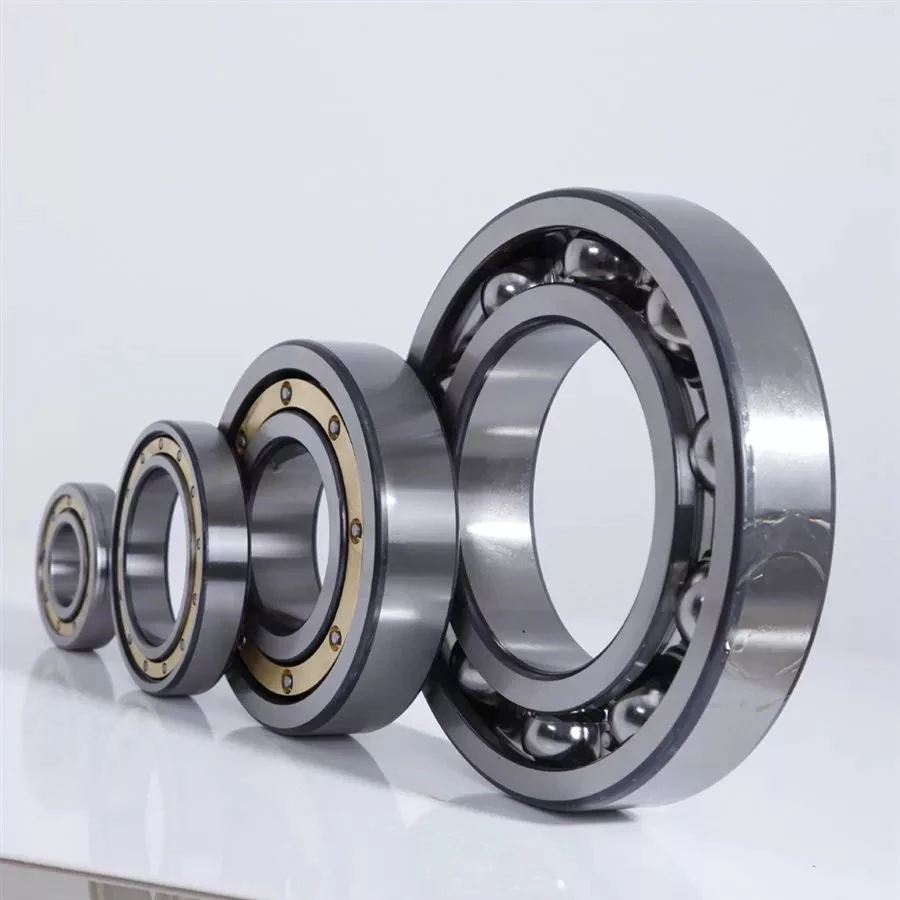
Types of Ball Bearings

There are many types of Ball Bearings available on the market, but which 1 is best for your application? Here, we will discuss the differences between Angular contact, Single-row, High-carbon steel, and Ceramic ball bearings. These types of bearings also feature races, or a groove in the center of each. These races are important in keeping the balls contained within the cylinder. They also provide a groove-baed pathway.
bearing

Ceramic

The ceramic ball used in ball bearings has many advantages. It is lightweight, operates at lower temperatures, has reduced skidding, and is resistant to electrolysis. The ball also exhibits longer fatigue life. All of these factors make the ceramic ball a good choice for many applications. But, how do you know if a ceramic ball bearing is right for your application? Read on to discover why ceramic ball bearings are a better choice than steel or stainless steel ones.
The ceramic balls are 40% more dense than steel. This means less centrifugal force is generated on the bearing, which suppresses heat generation. Because of this reduced friction, ceramic bearings are more efficient at transferring energy. Compared to steel bearings, ceramic balls have longer life spans. Nonetheless, these ceramic balls aren’t as strong as steel. Therefore, it is important to understand the limitations of the ceramic ball bearing before buying one.
The ceramic materials used for ball bearings are resistant to micro-welding. Metals undergo this process when imperfections in the surfaces interact. Eventually, this results in a brittle ball that reduces the life of a bearing. Unlike metals, ceramic materials have a stable behavior at high temperatures and exhibit less thermal expansion. This means that they can be used for applications where lubrication isn’t an option.
While steel balls can easily absorb contaminants and foreign particles, the ceramic ball is insensitive to this, and doesn’t require lubrication. This means they’re not susceptible to corrosion and other common problems. These are just a few reasons why ceramics are a better choice. This technology has a wide range of uses. It’s easy to see why it is so popular. If you’re looking for a new bearing for your application, be sure to contact an AST Applications Engineer. They can analyze your operating conditions and potential failure modes.

Angular contact

An Angular Contact Ball Bearing (also known as an angular-contact bearing) has an axial component that is generated when radial loads are applied. They are generally used in pairs, triplex sets, or quadruplex sets. These bearings are also available with Super Finished Raceways to reduce noise and improve lubricant distribution. Angular contact ball bearings have various design units, such as bore size, outer diameter, and outer ring width.
A single-row angular contact bearing has a radial contact angle that is equal to the angular distance between the 2 rings. Double-row angular bearings are designed for two-way thrust capability. These types of bearings can be purchased at Grainger and other online retailers. A typical angular contact bearing will last up to a million revolutions. They are often used in industrial angular contact bearings.
Single-row angular contact ball bearings feature a set contact angle. These bearings can support radial and axial loads, but they can’t withstand high speeds. Single-row angular contact ball bearings may also have 1 or 2 shoulders relieved. Thrust load is a pressure placed on the bearing when it is installed in an assembly, and it is used to create an angle between the races.
Angular contact ball bearings come in single and double-row configurations. They differ in the axial load they can carry and the type of lubrication they use. Angular contact ball bearings are ideal for high-speed applications and can accommodate both radial and axial loads. The type of contact and lubrication used in angular-contact ball bearings depends on the intended use for the bearing.
bearing

High-carbon steel

Carbon steel is a low-alloy and high-carbon steel used in bearings. This material provides superior strength and fatigue properties for ball and roller bearings. Its mechanical properties are ideal for applications where the temperature is less than 400 degrees Fahrenheit. High-carbon steel is also used to make bearing components for chrome steel bearings. These types of steels are softer than chrome steel but provide superior durability in applications where the material is exposed to severe conditions.
Hardened carbon steel balls with an AISI 1015 hardness index are used in a variety of automotive, commercial, and semi-precision applications. In addition to automotive applications, they are also used in slides, trolleys, and conveyors. AISI 1015 carbon steel balls are used in bearings. They can be purchased in a variety of weights and diameters. Carbon steel balls can also be purchased in nickel-plated or uncoated varieties for decorative purposes.
In order to determine whether a ball bearing is made of high-carbon steel, the material must be tested for its hardness. An ordinary pocket magnet will work well, but an ordinary rare earth magnet isn’t powerful enough to measure the hardness. If it attracts the magnet strongly, the metal is steel, while a weak magnet indicates a non-ferrous material. A hardness test requires a special microhardness test.
A lower-carbon steel is another option. Some miniature bearing manufacturers use a material with less carbon than AISI 440C. This material is also known as KS440 or X65Cr13. After being heat-treated, it develops smaller carbides, resulting in superior low-noise characteristics and the same corrosion-resistance as 440C. These materials are a less expensive alternative than chrome steel, but they are often less durable than chrome alloy steel.

Single-row

Single-row angular contact ball bearings accommodate axial loads in 1 direction. These are normally adjusted against a second bearing. Unlike other ball bearings, they are non-separable and contain an upper and lower shoulder. Single-row ball bearings are made of Chromium Steel (GCr15) which is heat-treated to achieve high uniform hardness and excellent wear resistance. They are the most commonly used type of bearings in the world.
Because of the angular contact between the radial plane and the raceway, single-row ball bearings transmit radial forces from raceway to raceway. A higher a, the greater the axial load carrying capacity of the bearing. Single-row angular contact ball bearings are ideal for high axial loads. However, they have limited preload capabilities and must be installed in pairs. Hence, they are best used for applications where axial forces must be distributed.
Single-row ball bearings can be pre-lubricated and have steel shields. They are also available with rubber seals or snap rings on the outside edge. They are available with various retainers, including pressed steel cages, plastic shields, and rubber seals. A tapered bore is also available upon request. They are ideal for applications where space is limited. The 6200 series of bearings are especially well suited for electrical motors, dental hand tools, and optical encoders.
Single-row angular contact ball bearings are widely used for axial loads. The outer and inner rings have slightly larger radii than the balls. These bearings can accommodate high speeds and low torque. They can also be supplied with different grease levels. If grease is needed, you can choose a lubricant that has different characteristics depending on the application. They are easy to install and maintain. However, they are not recommended for adjacent mounting.
bearing

Plastic

A plastic ball bearing is a highly versatile component that can be mounted in a variety of components, including wheels, pulleys and housings. The outer ring of a plastic bearing is usually the pulley profile. The inner ring can be made of a shaft or polymer. The integrated design of a plastic ball bearing helps to reduce assembly time and cost. Here are some of the benefits of this type of bearing:
First and foremost, plastic balls are lighter than metal balls. They also have less magnetic properties than steel balls, making them the best option for applications requiring low weight and noise. Glass balls are also lighter than stainless steel balls, making them the ideal metal-free choice. They are also very corrosion-resistant, which makes them a great choice for some applications. In addition to being lightweight, polymer ball bearings are also quiet. And because of their low weight, plastic ball bearings are ideal for applications that require fast speed.
Another advantage of plastic bearings is their ability to withstand high temperatures. This material is also abrasion and corrosion-resistant. It meets FDA and USDA acceptance requirements. Aside from its abrasion-resistant and corrosion-resistant properties, these plastics do not transfer heat. Aside from being extremely durable and flexible, most plastics are also self-lubricating. Common plastics include phenolics, acetals, nylon, and ultra high molecular weight polyethylene. Nonetheless, plastics have limitations, and these materials may be damaged by extreme temperatures or cold flow under heavy loads.
Other advantages of plastic ball bearings include their low density, high hardness and low friction coefficient, and ability to withstand heat and corrosion. Ceramics are also lightweight, non-conductive, and have superior resistance to friction. These products can withstand temperatures up to 1,800 degrees Fahrenheit. If you’re in the market for a plastic ball bearing, it’s important to choose the right type of material. And if you’re looking for a high-quality bearing, look no further.

China Hot selling Powder Metallurgy The Best Assy Gear Bevel and Shaft CZPT Tractor Spare Parts     near me supplier China Hot selling Powder Metallurgy The Best Assy Gear Bevel and Shaft CZPT Tractor Spare Parts     near me supplier

China Professional High Quality 2818 4660 0104 Tata Indica 7690955412 High Pressure Tractor Tata Power Steering Pump Spare Parts for Bus near me supplier

Product Description


GREEN Hydraulic
 is 1 strength Professional enterprise which integrates in Hydraulic Component with more than 15 years experience focusing on the abroad and Domestic Market. Our products including Piston Pump, Vane Pump, Gear Pump, Hydraulic Valve, Hydraulic Motor, Electric Motor, Oil Cooler, Accumulator and other hydraulic accessories etc. GREEN Hydraulic Piston Pump Series including CY, A2F, A2FO, A7V, A4V, A10V Series, which is the same as Orignal Rexroth, the same appreance, mounting size and working perofrmance. The products are widely used in machine tool, forging machinery, metallurgy machinery, engineering machinery, mine machinery and other hydraulic systems. They also can be used as hydraulic motors if the valve plate is changed into motor type. GREEN also supply replacement parts for Komatsu, Rexroth, Sauer, Hitachi, Catpillar, KYB, Kawasaki, Toshiba, Linde, Vickers, Yuekn, Nachi…Please consult online customer service for more models

Stiffness and Torsional Vibration of Spline-Couplings

In this paper, we describe some basic characteristics of spline-coupling and examine its torsional vibration behavior. We also explore the effect of spline misalignment on rotor-spline coupling. These results will assist in the design of improved spline-coupling systems for various applications. The results are presented in Table 1.
splineshaft

Stiffness of spline-coupling

The stiffness of a spline-coupling is a function of the meshing force between the splines in a rotor-spline coupling system and the static vibration displacement. The meshing force depends on the coupling parameters such as the transmitting torque and the spline thickness. It increases nonlinearly with the spline thickness.
A simplified spline-coupling model can be used to evaluate the load distribution of splines under vibration and transient loads. The axle spline sleeve is displaced a z-direction and a resistance moment T is applied to the outer face of the sleeve. This simple model can satisfy a wide range of engineering requirements but may suffer from complex loading conditions. Its asymmetric clearance may affect its engagement behavior and stress distribution patterns.
The results of the simulations show that the maximum vibration acceleration in both Figures 10 and 22 was 3.03 g/s. This results indicate that a misalignment in the circumferential direction increases the instantaneous impact. Asymmetry in the coupling geometry is also found in the meshing. The right-side spline’s teeth mesh tightly while those on the left side are misaligned.
Considering the spline-coupling geometry, a semi-analytical model is used to compute stiffness. This model is a simplified form of a classical spline-coupling model, with submatrices defining the shape and stiffness of the joint. As the design clearance is a known value, the stiffness of a spline-coupling system can be analyzed using the same formula.
The results of the simulations also show that the spline-coupling system can be modeled using MASTA, a high-level commercial CAE tool for transmission analysis. In this case, the spline segments were modeled as a series of spline segments with variable stiffness, which was calculated based on the initial gap between spline teeth. Then, the spline segments were modelled as a series of splines of increasing stiffness, accounting for different manufacturing variations. The resulting analysis of the spline-coupling geometry is compared to those of the finite-element approach.
Despite the high stiffness of a spline-coupling system, the contact status of the contact surfaces often changes. In addition, spline coupling affects the lateral vibration and deformation of the rotor. However, stiffness nonlinearity is not well studied in splined rotors because of the lack of a fully analytical model.
splineshaft

Characteristics of spline-coupling

The study of spline-coupling involves a number of design factors. These include weight, materials, and performance requirements. Weight is particularly important in the aeronautics field. Weight is often an issue for design engineers because materials have varying dimensional stability, weight, and durability. Additionally, space constraints and other configuration restrictions may require the use of spline-couplings in certain applications.
The main parameters to consider for any spline-coupling design are the maximum principal stress, the maldistribution factor, and the maximum tooth-bearing stress. The magnitude of each of these parameters must be smaller than or equal to the external spline diameter, in order to provide stability. The outer diameter of the spline must be at least 4 inches larger than the inner diameter of the spline.
Once the physical design is validated, the spline coupling knowledge base is created. This model is pre-programmed and stores the design parameter signals, including performance and manufacturing constraints. It then compares the parameter values to the design rule signals, and constructs a geometric representation of the spline coupling. A visual model is created from the input signals, and can be manipulated by changing different parameters and specifications.
The stiffness of a spline joint is another important parameter for determining the spline-coupling stiffness. The stiffness distribution of the spline joint affects the rotor’s lateral vibration and deformation. A finite element method is a useful technique for obtaining lateral stiffness of spline joints. This method involves many mesh refinements and requires a high computational cost.
The diameter of the spline-coupling must be large enough to transmit the torque. A spline with a larger diameter may have greater torque-transmitting capacity because it has a smaller circumference. However, the larger diameter of a spline is thinner than the shaft, and the latter may be more suitable if the torque is spread over a greater number of teeth.
Spline-couplings are classified according to their tooth profile along the axial and radial directions. The radial and axial tooth profiles affect the component’s behavior and wear damage. Splines with a crowned tooth profile are prone to angular misalignment. Typically, these spline-couplings are oversized to ensure durability and safety.

Stiffness of spline-coupling in torsional vibration analysis

This article presents a general framework for the study of torsional vibration caused by the stiffness of spline-couplings in aero-engines. It is based on a previous study on spline-couplings. It is characterized by the following 3 factors: bending stiffness, total flexibility, and tangential stiffness. The first criterion is the equivalent diameter of external and internal splines. Both the spline-coupling stiffness and the displacement of splines are evaluated by using the derivative of the total flexibility.
The stiffness of a spline joint can vary based on the distribution of load along the spline. Variables affecting the stiffness of spline joints include the torque level, tooth indexing errors, and misalignment. To explore the effects of these variables, an analytical formula is developed. The method is applicable for various kinds of spline joints, such as splines with multiple components.
Despite the difficulty of calculating spline-coupling stiffness, it is possible to model the contact between the teeth of the shaft and the hub using an analytical approach. This approach helps in determining key magnitudes of coupling operation such as contact peak pressures, reaction moments, and angular momentum. This approach allows for accurate results for spline-couplings and is suitable for both torsional vibration and structural vibration analysis.
The stiffness of spline-coupling is commonly assumed to be rigid in dynamic models. However, various dynamic phenomena associated with spline joints must be captured in high-fidelity drivetrain models. To accomplish this, a general analytical stiffness formulation is proposed based on a semi-analytical spline load distribution model. The resulting stiffness matrix contains radial and tilting stiffness values as well as torsional stiffness. The analysis is further simplified with the blockwise inversion method.
It is essential to consider the torsional vibration of a power transmission system before selecting the coupling. An accurate analysis of torsional vibration is crucial for coupling safety. This article also discusses case studies of spline shaft wear and torsionally-induced failures. The discussion will conclude with the development of a robust and efficient method to simulate these problems in real-life scenarios.
splineshaft

Effect of spline misalignment on rotor-spline coupling

In this study, the effect of spline misalignment in rotor-spline coupling is investigated. The stability boundary and mechanism of rotor instability are analyzed. We find that the meshing force of a misaligned spline coupling increases nonlinearly with spline thickness. The results demonstrate that the misalignment is responsible for the instability of the rotor-spline coupling system.
An intentional spline misalignment is introduced to achieve an interference fit and zero backlash condition. This leads to uneven load distribution among the spline teeth. A further spline misalignment of 50um can result in rotor-spline coupling failure. The maximum tensile root stress shifted to the left under this condition.
Positive spline misalignment increases the gear mesh misalignment. Conversely, negative spline misalignment has no effect. The right-handed spline misalignment is opposite to the helix hand. The high contact area is moved from the center to the left side. In both cases, gear mesh is misaligned due to deflection and tilting of the gear under load.
This variation of the tooth surface is measured as the change in clearance in the transverse plain. The radial and axial clearance values are the same, while the difference between the 2 is less. In addition to the frictional force, the axial clearance of the splines is the same, which increases the gear mesh misalignment. Hence, the same procedure can be used to determine the frictional force of a rotor-spline coupling.
Gear mesh misalignment influences spline-rotor coupling performance. This misalignment changes the distribution of the gear mesh and alters contact and bending stresses. Therefore, it is essential to understand the effects of misalignment in spline couplings. Using a simplified system of helical gear pair, Hong et al. examined the load distribution along the tooth interface of the spline. This misalignment caused the flank contact pattern to change. The misaligned teeth exhibited deflection under load and developed a tilting moment on the gear.
The effect of spline misalignment in rotor-spline couplings is minimized by using a mechanism that reduces backlash. The mechanism comprises cooperably splined male and female members. One member is formed by 2 coaxially aligned splined segments with end surfaces shaped to engage in sliding relationship. The connecting device applies axial loads to these segments, causing them to rotate relative to 1 another.

China Professional High Quality 2818 4660 0104 Tata Indica 7690955412 High Pressure Tractor Tata Power Steering Pump Spare Parts for Bus     near me supplier China Professional High Quality 2818 4660 0104 Tata Indica 7690955412 High Pressure Tractor Tata Power Steering Pump Spare Parts for Bus     near me supplier