Tag Archives: tractor tractor tractor

China Good quality Good Price Double Acting PC200 Tractor Hydraulic Cylinder Parts for Boom Arm Bucket with Free Design Custom

Product Description

Products Specifications:

Good price double acting PC200 tractor hydraulic cylinder parts for boom arm bucket 
PC200 Arm Cylinder
E320 Bucket Cylinder
CAT330 Boom Cylinder

Brand Model
Komatsu PC30,PC35,PC40,PC50,PC60,PW60,PW100,PC100,PC120,PC150,PC200,PC210,PC220,PC228,PC240
Kobelco SK07,SK12,SK60,SK75UR,SK100, SK220,SK230,SK258,SK300,SK330,SK350, SK450
Hitachi EX60,EX100,EX120, EX200,EX220, EX230,EX270,EX300,EX330,EX350
Caterpillar E70,E110,E120,E200,E240,E300,E307,E308,E312,E320,E322,E325,E330
Volvo EC55,EC210,EC240,EC290,EC360,EC450,EC460
Hyundai R55,R60,R110,R130,R150,R200.R210,R215,R220,R225,R260,R280,R305
Sumitomo SH100,SH120,SH200,SH300,SH350,SH450, LS260,LS265,LS280,LS580
Kato HD250,HD400,HD450,HD550,HD700,HD770,HD1250,HD1430,HD1880
Daewoo DH55,DH150,DH200,DH220,DH25,DH258-7, DH330,DH360, DH370,DH500

1. Seals kit: Superior quality named-brand seals, durable and hard-wearing with long service life.

2. Heat treatment: Quenching&Tempering which makes the piston rod super high hardness.

3. Cleaning: Ultrasonic cleaning.

4.Rod:Induction hardened prior to chrome plating enhances the surface hardness, improve corrosion resistance and anti-scratch performance.

5.Bushing: Hardened steel bushing or copper bushing.

Our business scope

  • 1. track link, track chain, track link assy, track group, track link with shoes.

  • 2. track roller, bottom roller, lower roller.

  • 3. carrier roller, top roller, upper roller.

  • 4. sprocket, driving wheel,

  • 5. idler, front idler, rear idler, 

  • 6. track adjuster, track tension spring, track cylinder, track cylinder assembly.

More Products From Us

About Us
We are located in HangZhou ZheJiang . We are a professional manufacturer that is specialized in producing High Quality Parts for Excavator, Bulldozer and other construction machines.
To ensure product quality, we are strict in quality control, from raw material, design, technology, manufacturing for the entire process of detection.

Contact Us

Benefits and Uses of Miter Gears

If you’ve ever looked into the differences between miter gears, you’re probably wondering how to choose between a Straight toothed and Hypoid one. Before you decide, however, make sure you know about backlash and what it means. Backlash is the difference between the addendum and dedendum, and it prevents jamming of the gears, protects the mating gear surfaces, and allows for thermal expansion during operation.
gear

Spiral bevel gears

Spiral bevel gears are designed to increase efficiency and reduce cost. The spiral shape creates a profile in which the teeth are cut with a slight curve along their length, making them an excellent choice for heavy-duty applications. Spiral bevel gears are also hypoid gears, with no offsets. Their smaller size means that they are more compact than other types of right-angle gears, and they are much quieter than other types of gear.
Spiral bevel gears feature helical teeth arranged in a 90-degree angle. The design features a slight curve to the teeth, which reduces backlash while increasing flexibility. Because they have no offsets, they won’t slip during operation. Spiral bevel gears also have less backlash, making them an excellent choice for high-speed applications. They are also carefully spaced to distribute lubricant over a larger area. They are also very accurate and have a locknut design that prevents them from moving out of alignment.
In addition to the geometric design of bevel gears, CZPT can produce 3D models of spiral bevel gears. This software has gained widespread attention from many companies around the world. In fact, CZPT, a major manufacturer of 5-axis milling machines, recently machined a prototype using a spiral bevel gear model. These results prove that spiral bevel gears can be used in a variety of applications, ranging from precision machining to industrial automation.
Spiral bevel gears are also commonly known as hypoid gears. Hypoid gears differ from spiral bevel gears in that their pitch surface is not at the center of the meshing gear. The benefit of this gear design is that it can handle large loads while maintaining its unique features. They also produce less heat than their bevel counterparts, which can affect the efficiency of nearby components.

Straight toothed miter gears

Miter gears are bevel gears that have a pitch angle of 90 degrees. Their gear ratio is 1:1. Miter gears come in straight and spiral tooth varieties and are available in both commercial and high precision grades. They are a versatile tool for any mechanical application. Below are some benefits and uses of miter gears. A simple explanation of the basic principle of this gear type is given. Read on for more details.
When selecting a miter gear, it is important to choose the right material. Hard faced, high carbon steel is appropriate for applications requiring high load, while nylon and injection molding resins are suitable for lower loads. If a particular gear becomes damaged, it’s advisable to replace the entire set, as they are closely linked in shape. The same goes for spiral-cut miter gears. These geared products should be replaced together for proper operation.
Straight bevel gears are the easiest to manufacture. The earliest method was using an indexing head on a planer. Modern manufacturing methods, such as the Revacycle and Coniflex systems, made the process more efficient. CZPT utilizes these newer manufacturing methods and patented them. However, the traditional straight bevel is still the most common and widely used type. It is the simplest to manufacture and is the cheapest type.
SDP/Si is a popular supplier of high-precision gears. The company produces custom miter gears, as well as standard bevel gears. They also offer black oxide and ground bore and tooth surfaces. These gears can be used for many industrial and mechanical applications. They are available in moderate quantities from stock and in partial sizes upon request. There are also different sizes available for specialized applications.
gear

Hypoid bevel gears

The advantages of using Hypoid bevel and helical gears are obvious. Their high speed, low noise, and long life make them ideal for use in motor vehicles. This type of gear is also becoming increasingly popular in the power transmission and motion control industries. Compared to standard bevel and helical gears, they have a higher capacity for torque and can handle high loads with less noise.
Geometrical dimensioning of bevel/hypoid bevel gears is essential to meet ANSI/AGMA/ISO standards. This article examines a few ways to dimension hypoid bevel and helical gears. First, it discusses the limitations of the common datum surface when dimensioning bevel/helical gear pairs. A straight line can’t be parallel to the flanks of both the gear and the pinion, which is necessary to determine “normal backlash.”
Second, hypoid and helical gears have the same angular pitch, which makes the manufacturing process easier. Hypoid bevel gears are usually made of 2 gears with equal angular pitches. Then, they are assembled to match 1 another. This reduces noise and vibration, and increases power density. It is recommended to follow the standard and avoid using gears that have mismatched angular pitches.
Third, hypoid and helical gears differ in the shape of the teeth. They are different from standard gears because the teeth are more elongated. They are similar in appearance to spiral bevel gears and worm gears, but differ in geometry. While helical gears are symmetrical, hypoid bevel gears are non-conical. As a result, they can produce higher gear ratios and torque.

Crown bevel gears

The geometrical design of bevel gears is extremely complex. The relative contact position and flank form deviations affect both the paired gear geometry and the tooth bearing. In addition, paired gears are also subject to process-linked deviations that affect the tooth bearing and backlash. These characteristics require the use of narrow tolerance fields to avoid quality issues and production costs. The relative position of a miter gear depends on the operating parameters, such as the load and speed.
When selecting a crown bevel gear for a miter-gear system, it is important to choose 1 with the right tooth shape. The teeth of a crown-bevel gear can differ greatly in shape. The radial pitch and diametral pitch cone angles are the most common. The tooth cone angle, or “zerol” angle, is the other important parameter. Crown bevel gears have a wide range of tooth pitches, from flat to spiral.
Crown bevel gears for miter gear are made of high-quality materials. In addition to metal, they can be made of plastic or pre-hardened alloys. The latter are preferred as the material is less expensive and more flexible than steel. Furthermore, crown bevel gears for miter gears are extremely durable, and can withstand extreme conditions. They are often used to replace existing gears that are damaged or worn.
When selecting a crown bevel gear for a miter gear, it is important to know how they relate to each other. This is because the crown bevel gears have a 1:1 speed ratio with a pinion. The same is true for miter gears. When comparing crown bevel gears for miter gears, be sure to understand the radii of the pinion and the ring on the pinion.
gear

Shaft angle requirements for miter gears

Miter gears are used to transmit motion between intersecting shafts at a right angle. Their tooth profile is shaped like the mitre hat worn by a Catholic bishop. Their pitch and number of teeth are also identical. Shaft angle requirements vary depending on the type of application. If the application is for power transmission, miter gears are often used in a differential arrangement. If you’re installing miter gears for power transmission, you should know the mounting angle requirements.
Shaft angle requirements for miter gears vary by design. The most common arrangement is perpendicular, but the axes can be angled to almost any angle. Miter gears are also known for their high precision and high strength. Their helix angles are less than 10 degrees. Because the shaft angle requirements for miter gears vary, you should know which type of shaft angle you require before ordering.
To determine the right pitch cone angle, first determine the shaft of the gear you’re designing. This angle is called the pitch cone angle. The angle should be at least 90 degrees for the gear and the pinion. The shaft bearings must also be capable of bearing significant forces. Miter gears must be supported by bearings that can withstand significant forces. Shaft angle requirements for miter gears vary from application to application.
For industrial use, miter gears are usually made of plain carbon steel or alloy steel. Some materials are more durable than others and can withstand higher speeds. For commercial use, noise limitations may be important. The gears may be exposed to harsh environments or heavy machine loads. Some types of gears function with teeth missing. But be sure to know the shaft angle requirements for miter gears before you order one.

China Good quality Good Price Double Acting PC200 Tractor Hydraulic Cylinder Parts for Boom Arm Bucket     with Free Design CustomChina Good quality Good Price Double Acting PC200 Tractor Hydraulic Cylinder Parts for Boom Arm Bucket     with Free Design Custom

China Professional OEM Automatic CZPT Carton China Tractor Truck Part ODM with Best Sales

Product Description

Product Description

Factory Ball Joint  Tie Rod End
 

Detailed Photos


Company Profile

Certifications

Our Advantages


our customer


Our team


Packaging & Shipping


The benefits of using pulleys

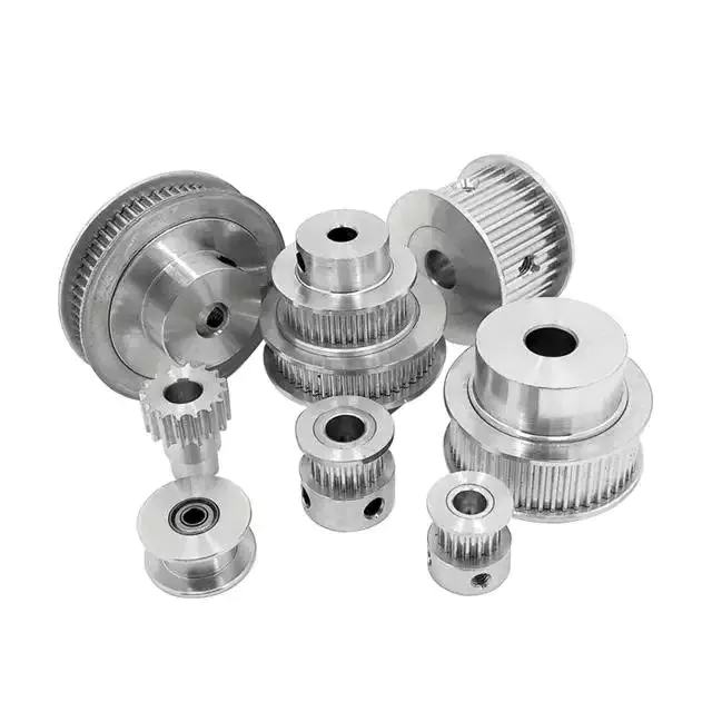
A pulley is a mechanical device that converts force into rotation. There are many advantages to using pulleys. Let’s take a look at a few of them. This article will describe the advantages, types, applications, and power sources of pulleys. You can then choose the pulley that best suits your specific needs. If you’re looking for a new tool to help you with a certain task, this article is for you.
pulley

Mechanical advantage

The mechanical advantage of a pulley can be defined as the ratio of applied force to the applied force. The mechanical advantage of a pulley can be calculated by considering several factors, including weight and friction. It can be calculated by the force applied per unit length of rope and the number of pulleys used. In a single-circuit system, the force required to lift a heavy object is equal to the user’s body weight.
The mechanical advantage of a pulley can be realized by comparing it to a seesaw. Both uses of rope are suitable for lifting objects. A rope 4 times heavier than a kilo is 4 times as effective. Because the forces on both sides of the pulley are equal, a small force is enough to move a large weight a short distance. The same force can be applied to a large mass to lift it several meters.
After introducing the concept of mechanical advantage, learners will practice using the pulley system. In addition to testing the pulley system, they should also calculate its mechanical advantage. Using either the instructor-provided handout or the learner’s workbook, students will determine how easily the pulley system functions. Once they have completed the test, they can discuss their results and how the system can be improved. These courses are best completed as part of a mini-unit or as a standalone main course.
The mechanical advantage of the pulley system is proportional to the number of rope loops. This circuit requires the same force as the dual circuit to lift heavy objects. A single lap requires only a third of the force to lift a double lap, while 3 laps require almost half the energy required for a single lap. The mechanical advantage of the pulley system becomes constant as the number of cycles increases.
The 3:1 Mechanical Advantage system feels like lifting a 300-pound load with 3 feet of rope. The three-foot-long rope moves the load 1 foot high. Understanding the mechanical advantages of pulleys is critical for rescuers when trying to create the perfect pulley system. Ideally, the pulley system will be anchored to a nearby rock, tree, pole or person – if the weight is not too heavy.
pulley

Types of pulleys

There are several types of pulleys. V-belt pulleys are the type commonly used in vehicles and electric motors. “V” pulleys require a “V” belt, and some even have multiple V grooves. “V” pulleys are often used in heavy duty applications for power transmission because they reduce the risk of power slippage.
Composite pulleys combine the properties of fixed and movable pulleys. Compound pulleys are able to change the direction of force while requiring relatively low force to move even the heaviest loads. Mechanical advantage is a measure of the effectiveness of a machine or equipment. It can be divided into 3 categories: force, distance and mechanics. Once you understand how each type works, you can design complex machines.
Fixed pulleys: These pulleys are the most basic type of pulleys. They use ropes and slotted wheels to move with the lifted object. Because they are so simple to set up, lifting heavy objects is a breeze. Although the moving object feels light, it is actually heavier than it actually is. These pulleys are used in construction cranes, utility elevators and many different industries.
Compound Pulley System: A pulley pulley is a combination of 2 fixed pulleys and 1 movable pulley. Compound pulley systems are effective for moving heavy objects because they have the largest force multipliers and are flexible enough to change the direction of the force as needed. Composite pulley systems are commonly used in rock climbing, theater curtains and sailing. If you’re looking for a pulley system, you can start by evaluating the types of pulleys and their uses.
Construction Pulleys: These are the most basic types of pulleys and have wheel rails. These pulleys can be lifted to great heights and attached to chains or ropes. They allow workers to access equipment or materials from greater heights. They are usually mounted on wheels with axles and secured with ropes. They are essential tools for construction workers. There are many different types of pulleys out there.

energy source

Belts and pulleys are mechanical devices used to transmit energy and rotational motion. The belt is connected to the rotating part of the energy source, and the pulley is mounted on the other. One pulley transmits power to the other, while the other changes the direction of the force. Many devices use this combination, including automobiles, stationary generators, and winches. It is used in many home applications, from conveyors to treadmills. Pulleys are also used for curtains in theater halls.
Pulley systems are an essential part of modern industry and everyday life. Pulleys are used in elevators, construction sites and fitness equipment. They are also used in belt-driven generators as backup power. Despite their simple and seemingly humble beginnings, they have become a versatile tool. From lifting heavy objects to guiding wind turbines, pulley systems are widely used in our daily lives.
The main reason why pulleys are so popular is the mechanical advantage they offer. They can lift a lot of weight by applying very little force over longer distances. For example, a small motor can pull 10 meters of cable, while a large motor can pull 1 meter. Also, the work done is equal to the force times the distance traveled, so the energy delivered to the large motor is the same.
The power source for the pulley system can be cables, belts or ropes. The drive element in a pulley system is usually a rope or cable. A belt is a loop of flexible material that transmits motion from 1 pulley to another. The belt is attached to the shaft and a groove is cut in the pulley. The belt then transfers energy from 1 pulley to the other through the system.
pulley

application

A pulley is a mechanical device used to lift heavy objects. They reduce the amount of work required to lift heavy objects and are an excellent choice for many applications. There are several different applications for pulleys, including elevators, grinders, planters, ladder extensions, and mountaineering or rock climbing. Let’s take a look at some of the most popular uses for pulleys in modern society. These include:-
A pulley is a mechanical device that changes force. To use, you wrap the rope around it and pull down to lift the object. While this device is very useful, a major limitation of using pulleys is that you still have to apply the same force to lift the object as you would without the pulleys. This is why people use pulleys to move large objects like furniture and cars.
In addition to lifting heavy objects, pulleys are used in elevators, flagpoles and wells. These systems allow people to move heavy objects without straining their backs. Many other examples of pulleys in the home include garage doors, flagpoles, and elevators. They also help raise and lower flagpoles, which can reach several stories high.
There are 2 basic types of pulleys: movable and fixed. Fixed pulleys are attached to a ceiling or other object using 2 ropes. Modern elevators and construction cranes use movable pulleys, as do some weight machines in gyms. Composite pulleys combine movable and fixed pulleys to minimize the force required to move heavy objects.
Another type of fixed pulley is the flagpole. A flagpole can support a country, organization, or anything else that needs to be lifted. A taller flagpole creates a prouder moment for those who support it. The operation of the rope and pulley mechanism is very simple. The user simply attaches the flag to the rope, pulls the pulley, and he or she can watch the flag rise and unfold.

China Professional OEM Automatic CZPT Carton China Tractor Truck Part ODM     with Best SalesChina Professional OEM Automatic CZPT Carton China Tractor Truck Part ODM     with Best Sales

China OEM OEM Precision Machining CNC Machinery Turning Tractor Part, Customized Stainless Steel CNC Machining Lathing Tractor Part near me supplier

Product Description

Product Description


Product  Name  Custom Precision CNC Turning Machining Aluminum Parts CNC Milling Parts from Factory Directly
Applicabe Material Stainless steel, carbon steel, alloy steel, titanium, titanium alloy, aluminum, copper, brass, bronze, plastic, peek,Teflon (PTFE, F4), PPSU,PSU,PEI,POM, etc(according to customer’s requirements).
Surface finish Machine finish/anodized/ beadblasting/Plating/Polish/brush/heat treatment/Brushed/Zinc plating/Nickel Plating/PVD etc.
Processing CNC machining, CNC milling and turning, drilling, grinding, cutting, stamping, tapping and other related equipment.
Application Medical treatment, electronics, communication security, petroleum, chemical industry, automation, light industrial machinery and other industries
File Format PDF/JPEG/AI/PSD/CAD/Dwg/Step/LGS
Payment Terms 50% deposit before production and 50% balance before arranging to ship.
Tolerance 0.01-0.02mm or accoriding to your requirment
Quality control 100%Inspection,Checking is during production process, after surface and before packing
Lead time 10-15 days for sample,15-25 days for bulk order depends on your design.
Package Standard package/ Pallet or container/ as per customized specifications
Shipment Express & air freight is preferred / sea freight/ as per customized specifications
Origin HangZhou China


Our Advantages

1) 10 years experiences in Precision CNC machining industry
2)  Advanced production and testing equipment 
3) Strict implementation of international quality standards and management system
4) Mature supplier chain to create value for customers 
5) Fast delivery and reasionable price 

Company Profile

       HangZhou Xihu (West Lake) Dis. ruijiadi hardware products factory is mainly engaged in the design and processing of precision fastening, connection and high-speed moving parts with corrosion resistance, high temperature resistance, high-voltage conductivity or insulation requirements in medical, electronic, communication and security, petroleum, chemical industry, automation light industrial machinery and other industries. It has CNC machining center, CNC walking machine, CNC lathe, CNC milling machine, automatic lathe and other related equipment.    

       Technical support and the best production scheme will be our greatest sincerity, and we are willing to cooperate with you for CZPT results.

Our Business:


FAQ

Q: Are you trading company or manufacturer?
A: We are 100 % factory, we warmly welcome you to pay us a visit and see our machining capabilities here in person.

Q: How long is your delivery time?
A: Generally it is 5-10 days if the design is simple to get machined. or it is 15-20 days if the goods are very complicated in machining structure, surely, it is according to machining difficulty and quantity.

Q: Do you provide samples ? is it free or extra?
A: Yes, we could offer the sample production before moving to mass production to test its quality. It takes the little cost of CNC Programme setting-up and surface finish, we ain’t making money from sample sometime we pay part of them for our customer since it’s the first time to work projects together .

Q:What kind of files do you accept?
A:PDF, DXF, ISG, STEP, X-T, High Resolution IPJ.

Q:What are your terms of delivery?
A:We accept EXW, FOB, CNF, etc. You can choose the most convenient one. Regarding to the shipping cost, if you have your own express account that will be welcome.

Q: What are your terms of payment?
A: 50% T/T in advance, balance before shipment.


Applications of Spline Couplings

A spline coupling is a highly effective means of connecting 2 or more components. These types of couplings are very efficient, as they combine linear motion with rotation, and their efficiency makes them a desirable choice in numerous applications. Read on to learn more about the main characteristics and applications of spline couplings. You will also be able to determine the predicted operation and wear. You can easily design your own couplings by following the steps outlined below.
splineshaft

Optimal design

The spline coupling plays an important role in transmitting torque. It consists of a hub and a shaft with splines that are in surface contact without relative motion. Because they are connected, their angular velocity is the same. The splines can be designed with any profile that minimizes friction. Because they are in contact with each other, the load is not evenly distributed, concentrating on a small area, which can deform the hub surface.
Optimal spline coupling design takes into account several factors, including weight, material characteristics, and performance requirements. In the aeronautics industry, weight is an important design factor. S.A.E. and ANSI tables do not account for weight when calculating the performance requirements of spline couplings. Another critical factor is space. Spline couplings may need to fit in tight spaces, or they may be subject to other configuration constraints.
Optimal design of spline couplers may be characterized by an odd number of teeth. However, this is not always the case. If the external spline’s outer diameter exceeds a certain threshold, the optimal spline coupling model may not be an optimal choice for this application. To optimize a spline coupling for a specific application, the user may need to consider the sizing method that is most appropriate for their application.
Once a design is generated, the next step is to test the resulting spline coupling. The system must check for any design constraints and validate that it can be produced using modern manufacturing techniques. The resulting spline coupling model is then exported to an optimisation tool for further analysis. The method enables a designer to easily manipulate the design of a spline coupling and reduce its weight.
The spline coupling model 20 includes the major structural features of a spline coupling. A product model software program 10 stores default values for each of the spline coupling’s specifications. The resulting spline model is then calculated in accordance with the algorithm used in the present invention. The software allows the designer to enter the spline coupling’s radii, thickness, and orientation.
splineshaft

Characteristics

An important aspect of aero-engine splines is the load distribution among the teeth. The researchers have performed experimental tests and have analyzed the effect of lubrication conditions on the coupling behavior. Then, they devised a theoretical model using a Ruiz parameter to simulate the actual working conditions of spline couplings. This model explains the wear damage caused by the spline couplings by considering the influence of friction, misalignment, and other conditions that are relevant to the splines’ performance.
In order to design a spline coupling, the user first inputs the design criteria for sizing load carrying sections, including the external spline 40 of the spline coupling model 30. Then, the user specifies torque margin performance requirement specifications, such as the yield limit, plastic buckling, and creep buckling. The software program then automatically calculates the size and configuration of the load carrying sections and the shaft. These specifications are then entered into the model software program 10 as specification values.
Various spline coupling configuration specifications are input on the GUI screen 80. The software program 10 then generates a spline coupling model by storing default values for the various specifications. The user then can manipulate the spline coupling model by modifying its various specifications. The final result will be a computer-aided design that enables designers to optimize spline couplings based on their performance and design specifications.
The spline coupling model software program continually evaluates the validity of spline coupling models for a particular application. For example, if a user enters a data value signal corresponding to a parameter signal, the software compares the value of the signal entered to the corresponding value in the knowledge base. If the values are outside the specifications, a warning message is displayed. Once this comparison is completed, the spline coupling model software program outputs a report with the results.
Various spline coupling design factors include weight, material properties, and performance requirements. Weight is 1 of the most important design factors, particularly in the aeronautics field. ANSI and S.A.E. tables do not consider these factors when calculating the load characteristics of spline couplings. Other design requirements may also restrict the configuration of a spline coupling.

Applications

Spline couplings are a type of mechanical joint that connects 2 rotating shafts. Its 2 parts engage teeth that transfer load. Although splines are commonly over-dimensioned, they are still prone to fatigue and static behavior. These properties also make them prone to wear and tear. Therefore, proper design and selection are vital to minimize wear and tear on splines. There are many applications of spline couplings.
A key design is based on the size of the shaft being joined. This allows for the proper spacing of the keys. A novel method of hobbing allows for the formation of tapered bases without interference, and the root of the keys is concentric with the axis. These features enable for high production rates. Various applications of spline couplings can be found in various industries. To learn more, read on.
FE based methodology can predict the wear rate of spline couplings by including the evolution of the coefficient of friction. This method can predict fretting wear from simple round-on-flat geometry, and has been calibrated with experimental data. The predicted wear rate is reasonable compared to the experimental data. Friction evolution in spline couplings depends on the spline geometry. It is also crucial to consider the lubrication condition of the splines.
Using a spline coupling reduces backlash and ensures proper alignment of mated components. The shaft’s splined tooth form transfers rotation from the splined shaft to the internal splined member, which may be a gear or other rotary device. A spline coupling’s root strength and torque requirements determine the type of spline coupling that should be used.
The spline root is usually flat and has a crown on 1 side. The crowned spline has a symmetrical crown at the centerline of the face-width of the spline. As the spline length decreases toward the ends, the teeth are becoming thinner. The tooth diameter is measured in pitch. This means that the male spline has a flat root and a crowned spline.
splineshaft

Predictability

Spindle couplings are used in rotating machinery to connect 2 shafts. They are composed of 2 parts with teeth that engage each other and transfer load. Spline couplings are commonly over-dimensioned and are prone to static and fatigue behavior. Wear phenomena are also a common problem with splines. To address these issues, it is essential to understand the behavior and predictability of these couplings.
Dynamic behavior of spline-rotor couplings is often unclear, particularly if the system is not integrated with the rotor. For example, when a misalignment is not present, the main response frequency is 1 X-rotating speed. As the misalignment increases, the system starts to vibrate in complex ways. Furthermore, as the shaft orbits depart from the origin, the magnitudes of all the frequencies increase. Thus, research results are useful in determining proper design and troubleshooting of rotor systems.
The model of misaligned spline couplings can be obtained by analyzing the stress-compression relationships between 2 spline pairs. The meshing force model of splines is a function of the system mass, transmitting torque, and dynamic vibration displacement. This model holds when the dynamic vibration displacement is small. Besides, the CZPT stepping integration method is stable and has high efficiency.
The slip distributions are a function of the state of lubrication, coefficient of friction, and loading cycles. The predicted wear depths are well within the range of measured values. These predictions are based on the slip distributions. The methodology predicts increased wear under lightly lubricated conditions, but not under added lubrication. The lubrication condition and coefficient of friction are the key factors determining the wear behavior of splines.

China OEM OEM Precision Machining CNC Machinery Turning Tractor Part, Customized Stainless Steel CNC Machining Lathing Tractor Part     near me supplier China OEM OEM Precision Machining CNC Machinery Turning Tractor Part, Customized Stainless Steel CNC Machining Lathing Tractor Part     near me supplier

China Custom Tractor Three Point Link Flail Mower Parts Ride on Lawn Mower with Free Design Custom

Product Description


MODEL AGL-125 AGL-145 AGL-165
Structure Weight 263kg 280kg 298kg
Tilt-Up Angle 90° 90° 90°
Tilt-Down Angle 55° 55° 55°
Cutting Width 1200mm 1400mm 1600mm
Flail Type Y Blade / Hammer
Number Of Flails Hammer: 18 / Y Blade: 36 Hammer: 22 / Y Blade: 44 Hammer: 26  /    Y Blade: 52   
Vertical Extending Distance 1415mm 1415mm 1415mm
Horizontal Extending Distance 1870mm 2070mm 2270mm
PTO Speed 540r/min 540r/min 540r/min
Tractor HP 20-40hp 30-45hp 40-50hp

The verge mower is ideal for roadside verge,tree trimming and general mulching. Side and inclining is hydraulic adjusted. 90°tilt up 55°tilt down or can cut directly behind the tractor. High power 50hp gearbox. Self leveling. High strength mulching blades. Safety fenders behind the mower to prevent the mud or small stones from the mower deck. Ideal for the smaller tractors due to their lighter weight design than the AGF model. Available cut sizes ranging from 1.25-1.65m.

HangZhou Qianyi Machinery Technology Co.,Ltd existing staff 50 people, in 2571 passed the ISO9001 quality system certification and passed CE certification.

Accumulated after years of development, we have many advanced equipment, like Germany fast Trulaser3030 laser cutting ,machine, CNC punch press TruPunch1000, CNC shearing machine, CNC lathe, bending machine, seam welding machine and more than 1 formula 1-160-1 high-end mechanical production equipment.

We provide good design, to help customers reduce costs of development and improve production efficiency. With complete testing equipment, strict quality control and abundant technical force, our machines are mainly exported to European, North American and Southeast Asian countries.

All of our machines are with 1 year warranty. We often insist on 1 principle”Better quality!Better service!Better price!”

Specifying a Ball Screw

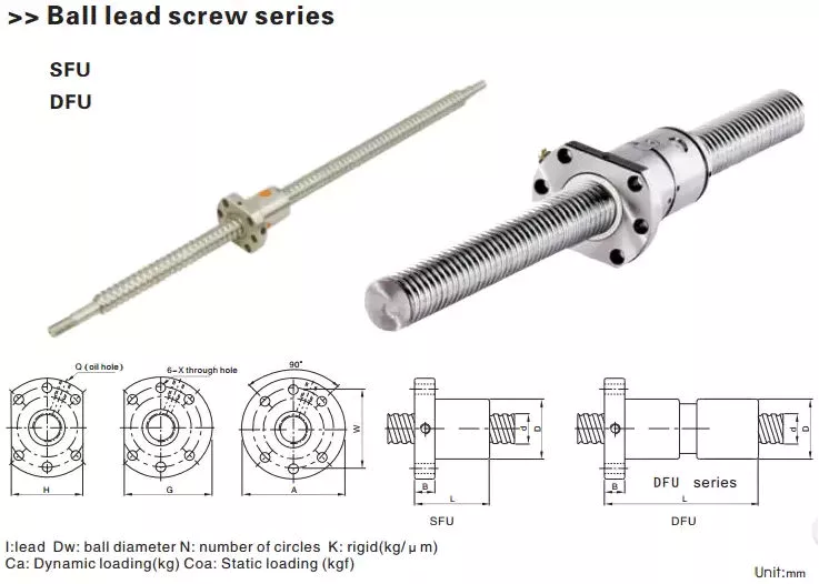
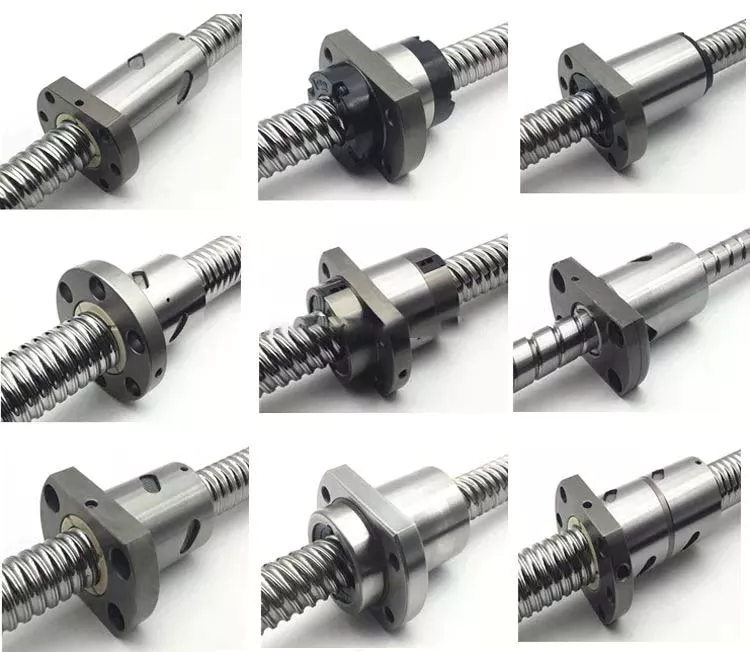
When you need a high-quality ball screw, it is important to select 1 with the proper dimensions and specifications. When you are looking for the best product, you should consider features such as preloading, surface finish, and internal return system. You can learn more about these features in this article. If you’re unsure which type of ball screw to select, contact a reputable supplier for further guidance. To find the best product for your needs, click here!
air-compressor

Brinelling

When specifying a Brinelling ball screw, it is crucial to know how much axial load it can safely bear. The static load capacity, which is given in the catalogue, applies only to pure axial loading, and any radial load that is smaller than 5% of the axial load won’t pose a problem. For more information, contact a CZPT engineer. Brinelling ball screw service life calculation should be performed using the following data:
Preload: The amount of load a ball screw can handle during a single revolution. Preload is the load applied before the ball screw starts moving, and the load is usually between 5 and 10 percent of the dynamic capacity. However, a ball screw that is subject to vibration will experience higher preload, requiring more frequent lubrication. The resulting mechanical stress may cause the ball screw to buckle, or cause the nut to re-circulate the balls.
Critical ball speed: The maximum speed at which the ball can move through the ball nut is called the critical ball speed. In contrast, running the ball screw at its critical shaft speed can lead to excessive vibrations, leading to premature failure of the end support bearings and brinelling of the ball track. Thus, it is recommended to operate a ball screw at a lower speed than the critical ball speed to prevent brinelling and plastic deformation of the balls.
False brinelling: False brinelling is a form of Fretting. False brinelling occurs when the bearings are not rotating. The movement will result in depressions or wear marks in the bearing raceway. This will cause noise, wear, and eventual fatigue. If these conditions persist, a newer ball screw should be used to test the system. The machine should be run for several hours and tested before replacing the bearing.

Preloading

The process of preloading ball screws minimizes backlash by applying pressure to the threads in the opposite direction of the screw’s direction of rotation. It prevents any movement of the screw relative to the nut. Various methods are used for preloading. A common 1 is to use oversized balls inside the ball nut. A double nut system may also be used. Both methods are equally effective. Regardless of the method used, the end result is the same – minimal backlash and increased efficiency.
In the conventional method of preloading ball screws, the motors operate simultaneously in opposite directions, causing them to have a relative motion of approximately equal magnitudes. This reduces the frictional resistance of the system, resulting in rapid traverse. The system is able to operate with minimal backlash during 110 inches of travel, reducing the heat developed by the drive nuts and the problems associated with ball screw heating. Moreover, this method can be used in a wide range of applications.
Another method of preloading ball screws is known as the ball-select method. This method includes the use of over-sized balls that force the balls into more contacts with the screw and nut than a normal ball screw. The advantage of this method is that it reduces backlash because the balls are not machined to high tolerances. The disadvantage of this method is that the ball screw will cost more to manufacture than a standard ball screw and nut.
A conventional design includes a mechanical mechanism that uses a series of balls to rotate a shaft. The problem of backlash is exacerbated by the mass of the shaft. The mechanical system is more complex than necessary and often requires a lot of effort. The present invention eliminates these problems by providing an improved method and apparatus for driving ball screws. This method provides a more efficient preload force that is dynamically adjustable while the mechanism is operating. The method can also improve friction and wear.
air-compressor

Internal return system

There are 2 different types of ball screws. The first type is external and the second is internal. The external type uses return tubes that protrude from the ball nut and extend above and around the outside of the screw. The internal type uses a single tube that spans the ball track, while the more common design uses multiple tubes spanning 1.5 to 3.5 ball tracks. The internal system involves a single return tube and several pickup fingers that guide the balls into the tubes.
The external return tube design is an easier, less expensive choice. The external ball return system has limited space but can handle a wide range of shaft diameters and leads. However, its physical size makes it incompatible with many high-speed applications. Therefore, careful consideration should be given to the mounting options. Internal ball return systems are best suited for small leads and ball sizes. Those that need a high speed will likely benefit from the external ball return system.
Internal ball screw technology has also kept pace with the demands of linear drive systems. Ball screw technology is now more durable than ever. Robust internal ball return systems circulate ball bearings through a solid pickup pin. These deflectors help the balls return to the screw in the correct location. They are crucial components in computer-controlled motion control systems and wire bonding. If you’re interested in the latest advances in linear screw technology, contact us today.
Ball screws are superior to lead screws in many ways. Ball screws are more efficient than lead screws, converting 90% of rotational motion into linear motion. As a result, they are more expensive than lead screws and acme screws. They also provide a smoother movement over the entire travel range. Furthermore, they require less power for the same performance. It’s no wonder that the ball screw is so popular in many different applications.

Surface finish

The surface finish of a ball screw is 1 of the key factors in determining the performance of the system. A ball screw with a good surface finish has superior performance in rolling resistance, backlash, and wear characteristics. However, it is critical to improve the surface finish of a ball screw to achieve precision movement, low wear, and low noise. To achieve this, special wire brushes will be used to polish precision-ground shafts.
For a ball screw to perform well, it must be hard, have a smooth surface, and retain lubricant. The surface finish of a ball screw should be smooth, free of cracks, and retain the lubricant well. Cracks and annealing are both undesirable during the manufacturing process, so a quality machine should be used for its surface finish. During the production process, a CBN cutting insert with full round or gothic arch profile can be used to achieve a high-quality surface finish.
Another finishing operation used in the manufacture of ball screws is lapping. Lapping improves surface quality and travel variation. It involves complex relative movements of abrasive particulates with the workpiece. This removes a thin layer of material from the workpiece, improving its surface quality and dimensional accuracy. The lapping process can be carried out under low-pressure conditions. It also enhances the friction torque and lubrication.
In lapping experiments, friction torque has the largest influence on travel variation and surface roughness. A friction torque of about 1 N x m is optimum. In addition, rotational speed has only a minimal effect. The best combination of these parameters is 1-1.5 N x m and 30 rpm. The minimum surface finish of a ball screw is around 800 mesh. The smallest variation in travel is observed at around half-way through the travel.
air-compressor

Lubrication

Proper lubrication of ball screw assemblies is critical to maintain optimum performance and life. Ball screw assemblies should be lubricated with grease, which is introduced directly into the ball nut. The lubrication port can be located at various locations on the product, including on the flange or in the external threads of the ball nut. Some ball nuts also feature a zerk fitting for easier lubrication.
The lubrication of ball screws is required in the case of operating conditions over 100oC. The minimum load for a ball screw is usually realized with a preload force. The lubricant is conveyed through the narrow lubrication gap due to the relative movement of the 2 surfaces. The increased viscosity of the lubricant enables separation of the contact surfaces. To avoid over-lubrication, it is important to check the lubricant level regularly.
The oil used in lubrication of ball screw assemblies can be either mineral or synthetic. The oil is composed of mineral or synthetic oil, additives, and a thickening agent, such as lithium or bentonite. Other thickening agents include lithium, barium complexes, or aluminum. The lubricant grade NLGI is a widely used classification for lubricating greases. It is not sufficient to choose a specific type of lubricant for a particular application, but it provides a qualitative measure.
Despite being essential to the performance of a ball screw, lubrication is also essential to its lifespan. Different types of lubricant offer corrosion protection. Before using a lubricant, make sure to thoroughly clean and dry the ball screw. If there is any buildup of dirt, it may damage the screw. To prevent this from occurring, you can use a solvent or lint-free cloth. Lubrication of ball screw assemblies can greatly extend the life of the assembly.

China Custom Tractor Three Point Link Flail Mower Parts Ride on Lawn Mower     with Free Design CustomChina Custom Tractor Three Point Link Flail Mower Parts Ride on Lawn Mower     with Free Design Custom

China Professional Customized Cast Tractor Spare Parts near me factory

Product Description

Product Introduction:

1.We can offer Casting sand casting parts according to your requirement
 1).ISO9001 SGS
2).OEM service available 
3).Materials: Cast Iron: Grey Iron castings/Gray Iron Castings, Malleable Iron Castings, Ductile Iron Castings, with Coated Sand Casting & Green Resin Sand Castings & Sand Castings
4).Process: sand casting
5).Weight range: 1KG-2TON
6.Application: Industrial parts, Machinery parts, hardware, construction parts, valvealve parts,train,craft,doorhandle,hinge,hydraulicpressure,construction,agricultural machinery 
7).Small orders accepted 
8).Make machining service as your requirement or drawings
9).Professional service 
10).Surface treatment,painting,zinc plating,machining center,,powder coating,Shot Blast,ect.
11).High quality and after sale service
12).Satisfying customers

Material grey cast iron, ductile cast iron, steel, stainless steel, brass, copper,
bronze, aluminum, zinc etc
Process sand casting, precision casting, CNC machining
Surface finish polishing, sand blasting, heat treatment, painting, powder coating,
anodizing, electroplating, mirror polishing.
Certificate ISO9001
Service OEM service available


2.OEM and CUSTOMIZED SERVICE

1).Quality guarantee

Chemical checking

NDE after rough machining

Mechanical testing after heat treatment

Final NDE,dimension inspected

2).Quality document

Full Q.A document as per client request

3).Packing and Shipping

standard export package(carton/wooden case/pallet)

accept FOB,FAS,CNF,CIF door to door etc or customer designated shipping agent

4).Service

Drawing: we can translate your original drawing, offer best suggestion on design

Quality: we have full set quality control system to guarantee the best quality.

Inspection: inspect in house, all our products must be checked 3 times before packing

5)Inspection

In-house Foundry

Third party inspection available upon requirement

HangZhou CZPT Machinery Co.,Ltd is 1 famous company in China which specialized in various metal casting products with over 10 years experience located in HangZhou China.It covers a comprehensive range of forging, stamping, sand casting, investment casting, die casting and machining and was widely used in Agriculture machinery, Motor Vehicle, Architecture,Railway and Engineering

As a professional company, CZPT have 4 groups of experienced teams to be in charge of deferent work:
Project team-customer service
Engineering team-provide R&D and technical support
QC team-productive process control and incoming parts inspection
Warehouse team-warehouse management and logistic service

Worm Gear Motors

Worm gear motors are often preferred for quieter operation because of the smooth sliding motion of the worm shaft. Unlike gear motors with teeth, which may click as the worm turns, worm gear motors can be installed in a quiet area. In this article, we will talk about the CZPT whirling process and the various types of worms available. We’ll also discuss the benefits of worm gear motors and worm wheel.
worm shaft

worm gear

In the case of a worm gear, the axial pitch of the ring pinion of the corresponding revolving worm is equal to the circular pitch of the mating revolving pinion of the worm gear. A worm with 1 start is known as a worm with a lead. This leads to a smaller worm wheel. Worms can work in tight spaces because of their small profile.
Generally, a worm gear has high efficiency, but there are a few disadvantages. Worm gears are not recommended for high-heat applications because of their high level of rubbing. A full-fluid lubricant film and the low wear level of the gear reduce friction and wear. Worm gears also have a lower wear rate than a standard gear. The worm shaft and worm gear is also more efficient than a standard gear.
The worm gear shaft is cradled within a self-aligning bearing block that is attached to the gearbox casing. The eccentric housing has radial bearings on both ends, enabling it to engage with the worm gear wheel. The drive is transferred to the worm gear shaft through bevel gears 13A, 1 fixed at the ends of the worm gear shaft and the other in the center of the cross-shaft.

worm wheel

In a worm gearbox, the pinion or worm gear is centered between a geared cylinder and a worm shaft. The worm gear shaft is supported at either end by a radial thrust bearing. A gearbox’s cross-shaft is fixed to a suitable drive means and pivotally attached to the worm wheel. The input drive is transferred to the worm gear shaft 10 through bevel gears 13A, 1 of which is fixed to the end of the worm gear shaft and the other at the centre of the cross-shaft.
Worms and worm wheels are available in several materials. The worm wheel is made of bronze alloy, aluminum, or steel. Aluminum bronze worm wheels are a good choice for high-speed applications. Cast iron worm wheels are cheap and suitable for light loads. MC nylon worm wheels are highly wear-resistant and machinable. Aluminum bronze worm wheels are available and are good for applications with severe wear conditions.
When designing a worm wheel, it is vital to determine the correct lubricant for the worm shaft and a corresponding worm wheel. A suitable lubricant should have a kinematic viscosity of 300 mm2/s and be used for worm wheel sleeve bearings. The worm wheel and worm shaft should be properly lubricated to ensure their longevity.

Multi-start worms

A multi-start worm gear screw jack combines the benefits of multiple starts with linear output speeds. The multi-start worm shaft reduces the effects of single start worms and large ratio gears. Both types of worm gears have a reversible worm that can be reversed or stopped by hand, depending on the application. The worm gear’s self-locking ability depends on the lead angle, pressure angle, and friction coefficient.
A single-start worm has a single thread running the length of its shaft. The worm advances 1 tooth per revolution. A multi-start worm has multiple threads in each of its threads. The gear reduction on a multi-start worm is equal to the number of teeth on the gear minus the number of starts on the worm shaft. In general, a multi-start worm has 2 or 3 threads.
Worm gears can be quieter than other types of gears because the worm shaft glides rather than clicking. This makes them an excellent choice for applications where noise is a concern. Worm gears can be made of softer material, making them more noise-tolerant. In addition, they can withstand shock loads. Compared to gears with toothed teeth, worm gears have a lower noise and vibration rate.
worm shaft

CZPT whirling process

The CZPT whirling process for worm shafts raises the bar for precision gear machining in small to medium production volumes. The CZPT whirling process reduces thread rolling, increases worm quality, and offers reduced cycle times. The CZPT LWN-90 whirling machine features a steel bed, programmable force tailstock, and five-axis interpolation for increased accuracy and quality.
Its 4,000-rpm, 5-kW whirling spindle produces worms and various types of screws. Its outer diameters are up to 2.5 inches, while its length is up to 20 inches. Its dry-cutting process uses a vortex tube to deliver chilled compressed air to the cutting point. Oil is also added to the mixture. The worm shafts produced are free of undercuts, reducing the amount of machining required.
Induction hardening is a process that takes advantage of the whirling process. The induction hardening process utilizes alternating current (AC) to cause eddy currents in metallic objects. The higher the frequency, the higher the surface temperature. The electrical frequency is monitored through sensors to prevent overheating. Induction heating is programmable so that only certain parts of the worm shaft will harden.

Common tangent at an arbitrary point on both surfaces of the worm wheel

A worm gear consists of 2 helical segments with a helix angle equal to 90 degrees. This shape allows the worm to rotate with more than 1 tooth per rotation. A worm’s helix angle is usually close to 90 degrees and the body length is fairly long in the axial direction. A worm gear with a lead angle g has similar properties as a screw gear with a helix angle of 90 degrees.
The axial cross section of a worm gear is not conventionally trapezoidal. Instead, the linear part of the oblique side is replaced by cycloid curves. These curves have a common tangent near the pitch line. The worm wheel is then formed by gear cutting, resulting in a gear with 2 meshing surfaces. This worm gear can rotate at high speeds and still operate quietly.
A worm wheel with a cycloid pitch is a more efficient worm gear. It reduces friction between the worm and the gear, resulting in greater durability, improved operating efficiency, and reduced noise. This pitch line also helps the worm wheel engage more evenly and smoothly. Moreover, it prevents interference with their appearance. It also makes worm wheel and gear engagement smoother.
worm shaft

Calculation of worm shaft deflection

There are several methods for calculating worm shaft deflection, and each method has its own set of disadvantages. These commonly used methods provide good approximations but are inadequate for determining the actual worm shaft deflection. For example, these methods do not account for the geometric modifications to the worm, such as its helical winding of teeth. Furthermore, they overestimate the stiffening effect of the gearing. Hence, efficient thin worm shaft designs require other approaches.
Fortunately, several methods exist to determine the maximum worm shaft deflection. These methods use the finite element method, and include boundary conditions and parameter calculations. Here, we look at a couple of methods. The first method, DIN 3996, calculates the maximum worm shaft deflection based on the test results, while the second one, AGMA 6022, uses the root diameter of the worm as the equivalent bending diameter.
The second method focuses on the basic parameters of worm gearing. We’ll take a closer look at each. We’ll examine worm gearing teeth and the geometric factors that influence them. Commonly, the range of worm gearing teeth is 1 to four, but it can be as large as twelve. Choosing the teeth should depend on optimization requirements, including efficiency and weight. For example, if a worm gearing needs to be smaller than the previous model, then a small number of teeth will suffice.

China Professional Customized Cast Tractor Spare Parts     near me factory China Professional Customized Cast Tractor Spare Parts     near me factory

China high quality OEM CNC Sand Casting and Machining Tractor Parts near me factory

Product Description

About us

HangZhou CZPT Precision Machinery Co., Ltd. specializes in machining all sorts of high precision machinery components, precision CNC metal and non-metal machining parts with various surface treatments, which apply to packaging machines, printing machines, assembly machinery, electronic packing facilities, metal processing facilities, food machinery and pharmaceutical industry, etc. We have been in CNC precision machining industry for over 10 years. We can manufacture all kinds of high precision machine parts with good quality and favorable prices.  

Features of CNC parts
1. Precision CNC parts strictly according to customers’ drawing,packing and quality request
2. Tolerance: Can be kept in +/-0.005mm
3. 100% inspection during production to ensure the quality
4. Experienced technology engineers and well trained workers
5. Fast and timely delivery. Speedy & professional service
6. Provide customer professional suggestion while in the process of customer designing to save cost.
7. Quality assurance in accordance with ISO9001
 

Material Stainless Steel SS201,SS303,SS304,SS316,SS416,SS420,17-4PH,SUS440C
Steel  Q235,C20,C45(K1045),1214,1215
Brass C36000(C26800),C37700(HPb59),C38500(HPb58),C27200(CuZn37),C28000(CuZn40/H62),C3604
Bronze C51000, C52100, C54400,CuSn8
Aluminum AL2571,AL5754(Almg3),AL5083,AL6061,AL6063,AL5052,AL7075
Alloy Steel SCM435,10B21
Plastic PA6,PA66,PP,PC,POM,FR4,ABS,Acrylic
Others According to customers’ requirements


Processing CNC machining, CNC milling and turning, drilling, grinding, stamping, tapping,bending
Finish Anodizing ,Heat treatment, polishing, powder coating, galvanized, electroplating, spraying, and painting
Dimensions According to customer’s drawing
Tolerance ±0.005mm
Drawing Format PDF/JPEG/AI/PSD/CAD/Dwg/Step/LGS
MOQ Negotiable
QC Policy 100% inspection and random inspection before shipment, with QC passed label
Stardard Materials and surface treatment comply with RoHS/Reach Directives
Processing Equipments CNC machining center, CNC milling machine, Drilling machine,grinding machine, CNC machining Puncher,
Milling machine,CNC wire-cut machine,Charmfering machine;
Testing Equipments CMM, Projector, Pull Tester, Automatic Optical Inspector, Salt Spray Tester, Durometer, Tensile Machine
Calipers, 
Application  Automation machine, medical device, industrial machine, automobile, electric appliance, robot, computers, tele-communication,and other industries
Packaging PE bags or bubble bags, boxes, cartons, pallet or as per customers’ requirements
Trade Terms EXW, FOB, CIF, As per customers’ request
Payment Terms Paypal or Western Union for sample orders; Larger amount by T/T with 30% as deposit,70% before shipment
Delivery Time Within 15-20 working days after deposit or payment received
Shipping Ports FOB HangZhou

FAQ

1: Are you a manufacturer?
We are a manufacturer.
 

2.When can I get the price?

Quotation will be provided within 24 hours after inquiry is received with full product information. 

3: How long is your delivery time?
Normally, the samples delivery is 10-15 days and the lead time for the official order is 30-45 days.
 
4: Do you provide samples ? 
Yes, we could offer the sample for free charge but do not pay the cost of express shipping fee 

We sincerely hope to cooperate with you in the future. If you have any questions or need more information about our products, please feel free to contact us.
 

Screw Shaft Types

If you’re looking for a screw shaft, but aren’t sure which type to buy, you’re in luck. In this article, we’ll talk about the different types, including Threaded shank, Round head, and Machined. Once you’ve read it, you’ll know which type to buy. Then, you can decide whether you want a ball screw nut or a threaded shank.

Machined screw shafts

Besides the standard stainless steel shaft, manufacturers also provide a variety of other materials, such as titanium, bronze, and brass. In addition to stainless steel, manufacturers also provide a variety of top-coating options, including zinc, brass, and chromium. Aluminum screws are not particularly durable and are easily affected by weather. Most screw shafts feature self-locking mechanisms. They are especially useful in C-clamps, vises, and screw-top container lids.
For applications where accuracy is vital, a ball screw shaft needs to be annealed. A heat treatment can be performed on the ball screw shaft to ensure that both ends are heated evenly. In this process, the shaft will be more durable, while maintaining its high-precision properties. These screw shafts are a key component in computer-controlled motion-control systems, wire bonding, and other industries that require high-precision and high-quality performance.
Depending on the material used, screw shafts can be made of stainless steel or titanium. High-precision CNC machines and lathes are typically used to manufacture screw shafts. Various shapes and sizes are available, each with a specific application. Whether you need a small or large screw, you can find 1 to fit your needs. And since each size requires a different material, your choice of material is important as well.
In general, the materials used for machining screw shafts are steel, stainless steel, titanium, brass, bronze, and aluminum. Metals that resist corrosion are also commonly used. Other materials for screw shafts are Teflon, nylon, and nylon. You can also find threaded screw shafts in materials such as porcelain, glass, and ceramic. If you want to use your screws in a unique material, consider purchasing a customized one.
screwshaft

Ball screw nuts

If you have a screw shaft, the last thing you want to worry about is the ball nut slipping off. To prevent this, you can place a temporary stop in the shaft’s grooves to ensure that the ball nut does not slide off. When you remove the stop, you can then install the ball screw nut. But, before you can install the ball screw nut, you have to make sure that you have a good grip on the shaft.
When selecting ball screw nuts, it’s important to consider how much preload you need to apply to avoid excessive backlash. Preloading eliminates this problem by making the ball nut compact. It also prevents backlash, which is lost motion caused by clearance between the ball and nut. Backlash disrupts repeatability and accuracy. This is where spacer preloading comes in. You can insert a spacer between the 2 ball nuts to transmit the force to the nut. However, you should keep in mind that this method reduces the load capacity of the ball screw.
The critical speed of a screw is the maximum rotating speed before it whips. This critical speed is influenced by several factors, including the diameter of the screw shaft, the number of support elements, and the material. By adjusting these factors, you can reduce the number of components used and the amount of time it takes to assemble the screw shaft. In addition, you can also reduce the number of components and avoid stacking tolerances. However, the critical speed of plastic nuts is limited due to sliding friction.
The ball screw nut has several characteristics that make it unique. Its most prominent feature is the presence of ball bearings. These balls help reduce friction between the screw nut and the shaft. Without ball bearings, the friction would be too high to function properly. Another important characteristic is the groove profile of the nut and ball. These 2 features ensure that the ball and the nut meet at 2 points. You’ll be amazed by the results of the work of these ball screw nuts.
screwshaft

Threaded shank

Wood screws are usually not fully threaded because the shank has an unthreaded portion at the top. This shoulder part forces the screw to compress 2 pieces of wood, which prevents the screw from overheating and compromising the materials strength. As the screw is threaded partially up, it is not as difficult to remove as a fully threaded screw. However, it is important to note that a wood screw will not hold as tightly as 1 with a fully threaded shank.
In addition to being universal, screw threads can be of different sizes. For example, a M8 screw has a thread pitch of 1.25 mm. To avoid confusion, screw thread pitches are commonly given with a multiplication sign. For example, M8x1 means that the screw is 8 mm in diameter but has a thread pitch of 1 mm per 360-degree rotation. Those who are not familiar with these dimensions may find it confusing.
The OD of the threaded portion of a bolt is generally smaller than the OD of the nut. If the shank is too deep for the nut to fit, the threads may bottom out. This is why it’s important to use a thread-cutting bit with a small thread diameter. You can use a micrometer or caliper to measure the thread diameter. This tool will also allow you to easily identify which screw size fits where and how well.
The metric system is the most widely used. Fasteners with DIN numbers are generally metric in size. This makes them very useful for industrial settings. You can find metric-sized screws anywhere, as long as you buy them from a reputable manufacturer. These fasteners also come with a dog point, which is used for safety wire. If the screw needs to be replaced, the shank can be drilled with a hole for a safety wire or for a dog-point.

Round head

A round head screw is the most common type used for machine screws. Other common types include truss head, flat head, and hexed head. Each has a different profile and are used for different purposes. A round head screw is typically wider than a flat or a hexed head, and has a slightly rounded surface. These screws are useful for projects involving sheet metal or sheet-metal parts. Round heads are usually slightly wider than a hex head screw, and they may also be used as a substitute for washers in certain applications. However, truss heads are not necessary for every project.
A wood screw has a smooth shank that protrudes above the surface of the material it is attaching. A metal screw has a threaded shaft that is fully threaded from head to point, and a fully threaded shaft provides more bite. Two common head styles are round head and pan head. If the task requires the screw to be flush or countersunk, the round head will be the best choice.
Another type is the Reed & Prince screw drive. These are similar to Phillips screws but have a 75-degree V shape. They are commonly used in marine hardware and are also known as BNAE NFL22-070. This type is also used for steel plate hangers. In addition to round head and pan head screws, there are a variety of other screw types. You can even get a head with a slotted head if you know where to look.
Screw diameters are specified according to the ISO 261 or ISO 262 standards. An M8 screw has a diameter of 8.25 mm. The M8 screw has a pitch of 1.25 mm, which is equivalent to 1 mm per 360 degrees. There are several other standard screw sizes and thread diameters available. You can find them all by consulting the relevant standards. But remember, the metric system is the most popular.
screwshaft

Self-locking mechanism

A self-locking mechanism for a screw shaft is a device that secures the screw to its supporting member in a failure position. The locking mechanism provides a positive connection between the screw shaft and the control surface during normal operation, and locks the screw to its supporting member when the screw fails. Previous attempts to solve this problem have typically used secondary nuts with free play on the screw, which were intentionally designed to jam when loaded. However, such a device can be unreliable, which is why the present invention offers a more robust and reliable locking mechanism.
The self-locking function of a screw depends on several factors, including its pitch angle and the coefficient of friction of the threads. The angle of friction must be less than the tangent of the material pairing to prevent untightening of the screw. Screws with self-locking mechanisms have an efficiency e lower than 50%, which is less than half. Self-locking screws also have the benefit of being less efficient than a standard screw.
Unlike a normal screw, a self-locking screw can be turned in either direction. The nut 22 rotates with the screw shaft, and the member 23 is translated in an axial direction. Regardless of the direction of the rotation of the screw, this axial translation will result in the opposite moment to that input moment. While screw self-locking mechanisms are typically less expensive, they are more reliable and durable.
Another important feature of self-locking screws is that they are not susceptible to independent loosening. The screw cannot rotate without a certain amount of torque. In addition, a self-locking screw shaft must have a small wedge with a smaller half-angle than the arctangent of the static friction. This means that the torque applied by the driver must be greater than the torque needed to overcome the friction.

China high quality OEM CNC Sand Casting and Machining Tractor Parts     near me factory China high quality OEM CNC Sand Casting and Machining Tractor Parts     near me factory

China Standard OEM High Precision Tractor Parts, Car Auto Parts, Car Parts with Good quality

Product Description

Quick Details

Shape:

Spur

Place of Origin:

HangZhou , China (Mainland)

Model Number:

BG0002

Brand Name:

AT

Material:

Steel

Product Type:

Non-Standard Product / Customize Product

Application Materials:

Iron, Steel, Brass, Copper, Aluminum and Stainless Steel

Machining Process:

Gear Hobbing, Shaping, Shaving, Grinding and CNC Machining

Surface Finish:

Anti-rust Treatment, Heat Treatment, Polishing and Coating Treatment

Surface Hardness:

HRC 28~32, HRC 40~44, HRC 58~62

Rust Protection Time:

2 Years Maximun

Tooth Profile Precision:

GB 5~8 level (AGMA 10~13 level)

Applicable Standard:

GB / ISO / DIN / JIS / AGMA

Quoted Condition:

2D / 3D Drawing / Sample

Quality Guarantee:

1 Year

Packaging & Delivery

Packaging Details: Anti-rust Paper, Small Box and Carton
Delivery Detail: 20 ~ 30 days

Product Overview

Packaging


Products Range

 Material  Carbon Steel  SAE1571, SAE1045, Cr12, 40Cr, Y15Pb, 1214L……
 Alloy Steel  20CrMnTi, 16MnCr5, 20CrMnMo, 41CrMo, 17CrNiMo5……
 Brass/Bronze  HPb59-1, H70, CuZn39Pb2, CuZn40Pb2, C38000, CuZn40……
 Machining Process

 Gear Hobbing, Gear Milling, Gear Shaping, Gear Broaching,

 Gear Shaving, Gear Grinding and Gear Lapping

 Modules  1.0, 1.25, 1.5, 1.75, 2.0, 2.25, 2.5……8.0
 Tolerance Control  Outer Diameter  ±0.005 mm
 Length Dimension  ±0.05 mm
 Teeth Accuracy  DIN Class 4, ISO/GB Class 4, AGMA Class 13, JIS Class 0
 Heat Treatment  Quenching & Tempering, Carburizing & Quenching, High-frequency Hardening, Carbonitriding……
 Surface Treatment  Blacking, Polishing, Anodization, Chrome Plating, Zinc Plating, Nickel Plating……
 Standard  European, American or Britain Standard

Factory Overview

ABOUT US:

As your one-stop source, AT PRECAST,we design, manufacturer and distribute precast concrete accessories including the Lifting Systems and Anchoring systems Coil and Ferrule Inserts. for Concrete and Prefabricated area.

As a leader in developing concrete accessory products, our main goal is to produce products that are safer, faster and more cost efficient.

With more than totally 50 years working experience, our entire staff is dedicated to provide you with the best customer service and competitive prices. Our sales force are CZPT to answer your questions quickly and offer you technical support .

Assurance:

 100% quality manufacturing.
 We guarantee that our products meet your supplied specifications
 Extremely competitive pricing
 Delivery to your port or front door
 4 —- 8 week lead times
 We handle all paperwork
 Partial container orders
 Flexible payment options
 Unique tooling options
 Full range of packaging options from bulk to retail ready
 Complete testing services available
 
FAQs:

1. Where is your location?

We are located in HangZhou City of China and are closed to Airport. It takes 30minuts by car from Liuting Airport our company.

2. How long has the company been established?

AT INDUSTRY was established in 2009. There is 6 years exporting experiences.

3. How many employees do you have?

Administration / sales    4
Engineering / design as our partner     8
Production as our partners 120
Quality assurance / inspection   10

4. Which countries do you export to?

U.S.A, Germany, France, Italy, UK, Brazil, Middle east of Asia, Thailand,

5. What proportion of your goods are exported?

100% of our production are exported to all over the world.

6. How long does it take to receive samples?

a) Pattern:30-45days after order 
b) Sample:30days after pattern finishing.
c) The lead time is the general production period and does not include the transportation time.

7. New product development process

Got tooling order and sample order with 50% deposit—Hold a meeting with the relation dept. to ensure the developing schedule—Design pattern, fixture and gauge and making them in our house—mold steel buying—Machining—Inspection—Send out the sample with initial inspection report.

8. How long is the manufacturing lead time?

Mass Production: 90days after sample approval by yours.
The lead time is the general production period including the transportation time.
We could make some special production arrangement effectively if customer has urgent need.

9. What basis can we buy goods?

We generally offer customers prices FOB& CIF (Carriage, Insurance & Freight). The CIF includes the freight cost to your nominated sea port.
We do provide clearance of goods which needs to be handled by a local freight forwarder.
All local costs and taxes are the responsibility of the buyer. We are happy to offer advisement on shipping if required.

10. What are the payment terms?

Payment terms are negotiable and will improve for long term customers.
During the initial stages, we request 50% of tooling fee in advance with the balance payable on acceptance of samples.
Production orders can be negotiable. We prefer 50% deposit and the balance by T/T before sails. But sometimes T/T 30 days after sails would also acceptable.

11. Which currency can we buy in?

We can deal in USD / Euro currency / GBP.

12. How long does it take to ship goods from China by sea?

It takes about 5 weeks to European ports plus 1 week customs clearance, so you can get the container within 6 to 7 weeks. It takes about 2 weeks to east coast and 3 weeks to west coast US ports. All sea goods are shipped from HangZhou Port.

13. How long does it take to ship goods from China by air?

It takes about 7 days to all major destinations.

14. Can we visit the factory to conduct an audit?

Yes, you are welcome to visit our partner factory by prior agreement.

15. How do we retain client confidentiality?

We are happy to sign Confidentiality Agreements with customers and will honor them.

16. Which languages do we do business in?

Although we do business with many countries around the world, we can only communicate effectively in Chinese English.
All information supplied should therefore be supplied in this form.

17. Is there a minimum volume of business required to conduct international purchasing?

There are no minimum volumes, but the prices of the goods, plus the fixed costs of importing makes it more economical to buy in high volumes. All potential customers will be assessed on an individual basis to determine if it appears a viable option for all parties to develop a relationship.

18. What type of parts you are specialized in?

Our business contains 2 areas,
one is for construction precast including lifting system, rigging hardware metal parts.
 
Another is customized metal business of quality sand castings, investment castings, lost foam castings, hot forgings, cold forgings, stampings, machined parts, injectionmolded plastics parts, etc.

19. Which kind of equipments do you have?

Forging friction press 160Ton, 300Ton, 630Ton, 1200Ton
Casting CZPT of 200kg, 500kg,1000kgs, 2000kgs
Press of 63ton, 120tons
CNC Machining center
CNC Vertical Lathe
CNC Lathe center
Boring machine
Drilling machine


The Functions of Splined Shaft Bearings

Splined shafts are the most common types of bearings for machine tools. They are made of a wide variety of materials, including metals and non-metals such as Delrin and nylon. They are often fabricated to reduce deflection. The tooth profile will become deformed with time, as the shaft is used over a long period of time. Splined shafts are available in a huge range of materials and lengths.

Functions

Splined shafts are used in a variety of applications and industries. They are an effective anti-rotational device, as well as a reliable means of transmitting torque. Other types of shafts are available, including key shafts, but splines are the most convenient for transmitting torque. The following article discusses the functions of splines and why they are a superior choice. Listed below are a few examples of applications and industries in which splines are used.
Splined shafts can be of several styles, depending on the application and mechanical system in question. The differences between splined shaft styles include the design of teeth, overall strength, transfer of rotational concentricity, sliding ability, and misalignment tolerance. Listed below are a few examples of splines, as well as some of their benefits. The difference between these styles is not mutually exclusive; instead, each style has a distinct set of pros and cons.
A splined shaft is a cylindrical shaft with teeth or ridges that correspond to a specific angular position. This allows a shaft to transfer torque while maintaining angular correspondence between tracks. A splined shaft is defined as a cylindrical member with several grooves cut into its circumference. These grooves are equally spaced around the shaft and form a series of projecting keys. These features give the shaft a rounded appearance and allow it to fit perfectly into a grooved cylindrical member.
While the most common applications of splines are for shortening or extending shafts, they can also be used to secure mechanical assemblies. An “involute spline” spline has a groove that is wider than its counterparts. The result is that a splined shaft will resist separation during operation. They are an ideal choice for applications where deflection is an issue.
A spline shaft’s radial torsion load distribution is equally distributed, unless a bevel gear is used. The radial torsion load is evenly distributed and will not exert significant load concentration. If the spline couplings are not aligned correctly, the spline connection can fail quickly, causing significant fretting fatigue and wear. A couple of papers discuss this issue in more detail.
splineshaft

Types

There are many different types of splined shafts. Each type features an evenly spaced helix of grooves on its outer surface. These grooves are either parallel or involute. Their shape allows them to be paired with gears and interchange rotary and linear motion. Splines are often cold-rolled or cut. The latter has increased strength compared to cut spines. These types of shafts are commonly used in applications requiring high strength, accuracy, and smoothness.
Another difference between internal and external splined shafts lies in the manufacturing process. The former is made of wood, while the latter is made of steel or a metal alloy. The process of manufacturing splined shafts involves cutting furrows into the surface of the material. Both processes are expensive and require expert skill. The main advantage of splined shafts is their adaptability to a wide range of applications.
In general, splined shafts are used in machinery where the rotation is transferred to an internal splined member. This member can be a gear or some other rotary device. These types of shafts are often packaged together as a hub assembly. Cleaning and lubricating are essential to the life of these components. If you’re using them on a daily basis, you’ll want to make sure to regularly inspect them.
Crowned splines are usually involute. The teeth of these splines form a spiral pattern. They are used for smaller diameter shafts because they add strength. Involute splines are also used on instrument drives and valve shafts. Serration standards are found in the SAE. Both kinds of splines can also contain a ball bearing for high torque. The difference between the 2 types of splines is the number of teeth on the shaft.
Internal splines have many advantages over external ones. For example, an internal spline shaft can be made using a grinding wheel instead of a CNC machine. It also uses a more accurate and economical process. Furthermore, it allows for a shorter manufacturing cycle, which is essential when splining high-speed machines. In addition, it stabilizes the relative phase between the spline and thread.
splineshaft

Manufacturing methods

There are several methods used to fabricate a splined shaft. Key and splined shafts are constructed from 2 separate parts that are shaped in a synchronized manner to transfer torque uniformly. Hot rolling is 1 method, while cold rolling utilizes low temperatures to form metal. Both methods enhance mechanical properties, surface finishes, and precision. The advantage of cold rolling is its cost-effectiveness.
Cold forming is 1 method, as well as machining and assembling. Cold forming is a unique process that allows the spline to be shaped to the desired shape. The resulting shape provides maximum contact area and torsional strength. Standard splines are available in standard sizes, but custom lengths can also be ordered. CZPT offers various auxiliary equipment, such as mating sleeves and flanged bushings.
Cold forging is another method. This method produces long splined shafts that are used in automobile propellers. After the spline portion is cut out, it is worked on in a hobbing machine. Work hardening enhances the root strength of the splined portion. It can be used for bearings, gears, and other mechanical components. Listed below are the manufacturing methods for splined shafts.
Parallel splines are the simplest of the splined shaft manufacturing methods. Parallel splines are usually welded to shafts, while involute splines are made of metal or non-metals. Splines are available in a wide variety of lengths and materials. The process is usually accompanied by a process called milling. The workpiece rotates to produce the serrated surface.
Splines are internal or external grooves in a splined shaft. They work in combination with keyways to transfer torque. Male and female splines are used in gears. Female and male splines correspond to 1 another to ensure proper angular correspondence. Involute splines have more surface area and thus are stronger than external splines. Moreover, they help the shaft fit into a grooved cylindrical member without misalignment.
A variety of other methods of manufacturing a splined shaft can be used to produce a splined shaft. Spline shafts can be produced using broaching and shaping, 2 precision machining methods. Broaching uses a metal tool with successively larger teeth to remove metal and create ridges and holes in the surface of a material. However, this process is expensive and requires special expertise.
splineshaft

Applications

The splined shaft is a mechanical component with a helix-like shape formed by the equal spacing of grooves in a circular ring. The splines can either have parallel or involute sides. The splines minimize stress concentration in stationary joints and can be used in both rotary and linear motion. In some cases, splines are rolled rather than cut. The latter is more durable than cut splines and is often used in applications requiring high strength, accuracy, and smooth finish.
Splined shafts are commonly made of carbon steel. This alloy steel has a low carbon content, making it easy to work with. Carbon steel is a great choice for splines because it is malleable. Generally, high-quality carbon steel provides a consistent motion. Steel alloys are also available that contain nickel, chromium, copper, and other metals. If you’re unsure of the right material for your application, you can consult a spline chart.
Splines are a versatile mechanical component. They are easy to cut and fit. Splines can be internal or external, with teeth positioned at equal intervals on both sides of the shaft. This allows the shaft to engage with the hub around the entire circumference of the hub. It also increases load capacity by creating a constant multiple-tooth point of contact with the hub. For this reason, they’re used extensively in rotary and linear motion.
Splined shafts are used in a wide variety of industries. CZPT Inc. offers custom and standard splined shafts for a variety of applications. When choosing a splined shaft for a specific application, consider the surrounding mated components, torque requirements, and size requirements. These 3 factors will make it the ideal choice for your rotary equipment. And you’ll be pleased with the end result!
There are many types of splines and their applications are endless. They transfer torque and angular misalignment between parts, and they also enable the axial rotation of assembled components. Therefore, splines are an essential component of machinery and are used in a wide range of applications. This type of shaft can be found in various types of machines, from household appliances to industrial machinery. So, the next time you’re looking for a splined shaft, make sure you look for a splined one.

China Standard OEM High Precision Tractor Parts, Car Auto Parts, Car Parts     with Good qualityChina Standard OEM High Precision Tractor Parts, Car Auto Parts, Car Parts     with Good quality

China OEM Best Accessory Newest Product 250W Electric Wheelchair Tractor Wheelchair Part near me factory

Product Description

Best wheelchair accessory Newest Product 250W Electric Wheelchair Tractor wheelchair part 

Simple, Reliable and economicBrand new design with better look, compact and fashion

Company Profile

HangZhou CZPT Medical Apparatus Co., Ltd. Locates in HangZhou covering about 2000 square meters. We specialize in research, design and manufacturing of Rehabilitation Equipment, such as, Manual Wheelchair, Electric Wheelchair, Electric Standing Wheelchair, Electric Climbing Wheelchair, Knee CZPT and Scooter, and so on. As a manufacturer, we manufacture by ourselves, and sell by ourselves as well.

Our company has integrated research and development, manufacturing and sales together and totally has more than 100 employees in Purchasing Department, Production Department, Design Department, Quality Department and Sales Department. We put high attention on researching and improving our products, for the time being, there are 4 professional technicians here. The products have gained ISO9001: 2000 Certificates, ISO13485: 2012 Certificates, FDA and CE as well, which ensures high quality and safety.

“JBH” as our registered trademark is a famous wheelchair brand both in domestic and international market and has a large products family covering Home Care, Rehabilitation Nursing, Professional Sports, Scooter, Commode Chair, Cane and etc.

Product Parameters


item value
Properties Rehabilitation Therapy Supplies
Place of Origin China
  ZheJiang
Brand Name JBH
Model Number T01
Type Handicapped Scooters
Brand / Model: JBH / T01
Power: 250W
Driving Range: 30 km
Climbing Capacity: 10 Degree
Certification: CE
Motor: 250W Hub Motor
Wheel Size: 12 inch
Battery: 36V 10AH
Foldable: Yes
Max Speed: 25km/h

FAQ
1. who are we?
We are based in ZheJiang , China, start from 2019,sell to North America(40.00%),Central America(10.00%),Domestic Market(10.00%),Northern Europe(5.00%),Western Europe(5.00%),Southern Europe(5.00%),Mid East(5.00%),Eastern Europe(5.00%),Southeast Asia(5.00%),South America(5.00%),Africa(3.00%),Eastern Asia(2.00%). There are total about 301-500 people in our office.

2. how can we guarantee quality?
Always a pre-production sample before mass production;
Always final Inspection before shipment;

3.what can you buy from us?
Power Wheelchair,Mobility Scooter,Manual Wheelchair,Mask,Hospital Bed

4. why should you buy from us not from other suppliers?
JBH Medical is a manufacturing base company with integration of research and development, covering 146,000 square meters. Approved by ISO9001, ISO14001, ISO13485 international quality systems. CZPT Products have acquired the certifications of FDA and CE.

5. what services can we provide?
Accepted Delivery Terms: FOB,CFR,CIF,EXW;
Accepted Payment Currency:USD,EUR,AUD,HKD;
Accepted Payment Type: T/T,PayPal,Western Union,Cash;
Language Spoken:English,Chinese

What is a pulley?

Pulleys are shafts or wheels on a shaft that support the movement and change of direction of a taut cable. The pulley also transfers power from the shaft to the cable. A simple pulley is used to raise the school flag. Read on to learn about the basic types of pulleys. We also covered the use of pulleys in everyday life. Read on to learn more about this important mechanical part.
pulley

composite pulley

A composite pulley is a mechanical system where 2 or more pulleys and ropes are connected together. It reduces the force required to lift the load because the force is divided by the distance of each pulley. Distance is equal to the mass of the object. Composite pulleys are a common mechanical system on sailboats. Composite pulleys can be used to lift heavy equipment such as sails.
The compound pulley unit consists of 2 pulleys, 1 fixed and the other movable. The fixed pulley is fixed overhead, while the movable pulley is connected to the load by a chain. The lift applies force to the other end of the rope. Anchor points are attached to fixed joists, ceiling joists or sturdy branches. The chain should be long enough to support the load during lifting.
Composite pulleys can be made from a variety of materials. Some are fixed and remain fixed. Others are detachable. The composite pulley combines the advantages of both types, making it a versatile tool. In the table below, these 3 types of pulleys are compared. It’s easy to see which 1 is best for your needs. The right choice depends on your specific needs and budget.
The compound pulley system consists of 2 fixed pulleys and 1 movable pulley. The compound pulley system multiplies the force by a factor of 2. The compound pulley system is particularly suitable for heavy loads and is ideal for construction sites. Workers apply less than half the load force on the composite pulley, significantly reducing the force required. This is a major benefit for many people.

Fixed pulley

Fixed pulleys are fixed gears of fixed length that are mounted on solid objects. There are many different types of pulley systems. Some cooperate with each other, but not “fixed”.
Fixed pulleys can be used for a variety of purposes. One application is to lift small objects. They have a one-to-1 mechanical advantage. Often, a single pulley can lift small loads. The force required to lift a single fixed pulley remains the same. They are usually used to lift lighter objects. They can even be attached to buckets used to draw water from wells.
While single fixed pulleys have desirable mechanical advantages, they are not suitable for force multipliers. Because their mechanical advantage diminishes over time, they are not effective force multipliers. They are used to redirect work so that it can be applied in the most convenient direction. This mechanical advantage is the main advantage of fixed pulleys and the most common way of moving objects. They have several benefits, including the ability to increase the speed of moving objects.
Another application for fixed pulleys is lifting supplies. A scaffold can weigh more than 1 and can be directly hoisted. In order to facilitate the transportation of materials, fixed pulleys are usually installed on the top of the scaffolding on construction sites. Then thread the rope through the edge of the groove that holds the pulley. The fixed pulley exerts the same force on the pull side as on the push side. The same is true for moving objects with fixed pulleys.
pulley

moving pulley

A movable pulley is a device whose part is fixed to another object, usually a rod or beam. The movable part moves with the load, making the load feel lighter. This is a useful tool for those who need to carry heavy items such as large bags. The advantages of moving pulleys are many. Here are some of them. Read on to learn more about them.
One of the most common uses of movable pulley systems is climbing high objects. Climbers act as pulley loads and pull ropes to lift objects. Eventually, when the traction stops, the climber descends. However, it is still a useful tool in other situations. The movable pulley system can help you climb the tallest objects or lift them to level surfaces.
Another example of movable pulleys is in industry. Depending on the load, movable pulleys make handling and moving loads easier. You can use them in a variety of applications in manufacturing and industry, including cleaning. For example, the American flag is raised and lowered every day. Removable pulleys are a handy tool when buildings need cleaning.
If you’re not sure whether a task requires a pulley, a zipline might be a good option. Connect the 2 ends of the rope and the pulley will move along the rope, then attach the rope to the metal cable. The load is the person holding the pulley, and the force comes from the attachment on the other end of the rope. There are 2 types of live pulleys: simple pulleys with just 1 wheel and live pulleys with many ropes attached.

School flag raised with simple pulleys

How is the school flag raised? It is pulled up by a rope attached to a pulley at the top of the pole. When the rope is pulled, the pulley turns, raising the flag. A pulley is a simple mechanism that helps people move heavier objects with ease. The rope must be securely attached to the pulley to keep the flag stable.
A simple pulley is a spinning wheel with grooves on 1 side and ropes on the other. The rope can be any length and the wheels can be any size. The rope has to go through the groove and the load is attached to the other end of the rope. Simple pulleys are pulleys with fixed shafts. An example is the wheel on a school flagpole.
A simple pulley system consists of a primary pole, a secondary pole and an outer member. The primary flagpole is connected to the track by a detour, while the secondary flagpole is connected to the track by a pipe. There is a groove on 1 side of the track, which passes through the inner cavity of the flagpole. An open track at the upper end of the track connects the 2 parts of the pulley.
A simple pulley can be used for many purposes. This is a useful machine that can be used to raise the flag. Among other things, it can be used in clothing lines, bird feeders, and even roofers. And, of course, you can use the pulley to raise the flag. Its versatility makes it an essential part of school decor.
pulley

cast iron pulley

If you are looking for pulleys for your machine, you may come across cast iron pulleys. They are usually cheap and available in a variety of sizes. The rim is held in place by a mesh attached to a central boss. The arms and spokes can be straight or curved, but most are oval. There are many uses for this type of pulley.
You might wonder why the arms of cast iron pulleys are so curved. Bent arms tend to yield rather than break. Cast iron pulleys are usually round with a slight bump on the rim, which helps keep the belt centered on the rim as it moves. On a 300mm diameter pulley, the bumps may be as small as 9mm.

China OEM Best Accessory Newest Product 250W Electric Wheelchair Tractor Wheelchair Part     near me factory China OEM Best Accessory Newest Product 250W Electric Wheelchair Tractor Wheelchair Part     near me factory

China OEM Hydraulic Steering Control Unit Tractor Parts 80cc with Good quality

Product Description

050 Series:
Small displacement series
Include: Open center and load sensing style
Displacement: 50/63(ml/r)

050 series PSU is a small displacement PSU.
The displacement includes: 50.63ml/r. It is typical used in mini engineering vehicles, such as small tractor.

Features:
1. The optimum design of spool and sleeve gains better characteristics.
2. Special casting design for low pressure drop.
3. Basic system open center.

Main Specification Data:
Max. System pressure-16Mpa
Max. Back pressure-2.1MPa
Input torque-1.7~2.5Nm
Max. System operating temperature-93° C

Recommended oil filtration-ISO19/16

What is a bushing?

If you’ve ever wondered what an enclosure is, you’ve come to the right place. This article will provide an overview of different types of housings, including air-insulated, oil-impregnated porous bronze, and epoxy-impregnated capacitor cells. After reading this article, you will be better equipped to make an informed choice about the type of bushings your truck needs.
bushing

air insulating sleeve

When choosing bushings for your electrical application, you need to look for bushings with long-lasting insulation. In addition to being durable, bushings must have the correct design shape and material to remain effective over time. Porcelain was used in early casing designs and was chosen for indoor and outdoor applications due to its low cost and low linear expansion. Porcelain also requires a lot of metal fittings and flexible seals to remain effective.
Solid bushings have a center conductor and a porcelain or epoxy insulator. They are used in low voltage electrical applications such as small distribution transformers and circuit switches. However, their low radial capacity limits their use in high-voltage applications, so they are limited to circuit switches and other low-voltage equipment. The electrical service duty of the bushing determines the type of insulation required.
Another type of air-insulated bushing is made of conductive metal, which reduces heat transfer. This design enables it to operate over a range of temperature conditions. Additionally, air-insulated bushings are generally more effective than gas-insulated bushings in a range of applications. The main difference between air-insulated bushings and gas-insulated bushings is the insulating material. While gas-insulated bushings are usually made of high-quality materials, high-quality materials are still preferred in some applications.
Elliott # B series insulators are 25 kV class and pressure molded cycloaliphatic epoxy resins. They feature knurled brass inserts and 16 UNC threads. If you choose this type, make sure it matches the exact diameter of your Elliott Class 25 kv air insulated bushing. These insulators also provide overall shielding and require openings to fit inch diameters.
There are 2 types of air-insulated bushings: air-to-air and oil-to-oil. Oil is a stronger dielectric than air, and air-to-oil bushings are used to connect atmospheric air to oil-filled equipment. They are available for solid and capacitive hierarchies. So, which 1 is right for you? Just choose the right insulation to make your equipment as efficient as possible.

Oil Impregnated Porous Bronze Bushings

Oil-impregnated porous bronze (PbB) bushings are 1 of the best options for lubricating metal bearings. Lubrication is maintained even in high temperature applications as oil penetrates into the pores of the bronze. They are also self-lubricating and maintenance-free. Manufactured by CZPT, the Oil Impregnated Bronze Bushing is a powder metal process that is uniformly lubricated by a uniform oil film. This type of bearing is 1 of the most efficient in terms of precision performance.
One major difference between oil-impregnated bronze bushings and standard cast bronze bushings is their manufacturing process. Oil-impregnated bronze bushings are pressed from powder and then sintered to form a hardened part. This method is very effective for high-volume manufacturing, but it also has its limitations. Oil-impregnated bronze bushings are cheaper and more efficient, but they have mechanical limitations.
The production of oil-impregnated porous bronze bushings is simple. Powder bronze bushings are pressed and vacuum sealed by forcing oil into the pores. The low stress properties of oil-impregnated bronze bushings make them easier to manufacture in high volume. It also does not require additional lubrication. However, oil-impregnated porous bronze bushings have relatively low mechanical strength and are not recommended for applications where high temperatures are present.
Oil Impregnated Porous Bronze is also known as BPPB. Unlike traditional oil-impregnated bronze bushings, BPPB bushings have a high oil retention capacity. This means they will last a long time and you will save a lot of maintenance costs. But be careful. Porous bronze bushings can only last so long without oil.
Oil-impregnated bronze bushings are a good choice if dimensional consistency is important. BP bronze bushings have the same C dimension as solid metal bushings. While the CZPT is a ghost of the past, there are now many powder metal manufacturers producing BP housings. Their C of F values ​​range from 0.04 to 0.08.
bushing

Epoxy Impregnated Capacitor Batteries

Epoxy impregnated condenser core sleeves are conductive paper used in air conditioning systems. The paper core is coated with epoxy resin and the insulating shell is silicone rubber. RIP bushings have excellent electrical properties, are fire resistant and are relatively small. However, the process of making these products is not easy and mistakes are common. These defects manifest as cracks or other structural damage in the capacitor cells.
RIF (Resin Impregnated) bushings feature a finely graded design. The capacitor core is made of glass fiber impregnated with epoxy resin. The outer insulation is made of silicone rubber sheds glued directly to the capacitor core. These bushings are designed for small clearances, so no filler material is required.
In order to determine whether the RIP sleeve is void-free and dry, the insulating paper must be impregnated with epoxy resin. The process is similar to making conventional condenser core sleeves, but with greater flexibility and robustness. The main difference between RIP bushings and conventional insulators is the epoxy content.
Capacitor grading bushings are also available. These bushings increase the electric field at the ends of the capacitor core plates. The higher the temperature, the higher the electric field. These properties make resin-impregnated capacitor mandrel sleeves reliable. However, capacitor grade bushings have higher electric fields than nonlinear bushings.
The capacitor core of the present invention is made by winding paper around the winding tube 3 . The paper may contain an intermediate conductive foil. The winding tube is then covered with electrical insulator. Afterwards, the capacitor core 1 will be RIP and electrically connected to the electrical conductor 6 .
To further characterize the performance of RIPs, thermal shock current (TSC) was used to determine their trap parameters. Unmodified epoxy resin and nano-SiO2 modified RIP were tested. The RIP samples were polarized under a 2 kV/mm electric field at 333 K for 10 min and then subcooled to 193 K with liquid nitrogen. TSC curves were obtained at 3 K/min and 383 K.
bushing

plastic bushing

Plastic bushings are essential for many industries. They protect wires and other mechanical parts. They come in many shapes and sizes and are often used as adapters when connecting 2 pipes or tubes of different diameters. They are available in a variety of materials including rubber, steel and various other plastics. Most bushings are cylindrical or conical in shape and made of shock absorbing material. They slide on rods or pipes to provide low friction motion.
Plastic bushings can be made from a variety of materials, including phenolic, polyethylene, and nylon. While phenolic resins have long been the preferred choice for heavy-duty applications, nylon is the most commonly used lining plastic. Nylon has several advantages, including low friction, no lubrication, quiet operation, and low wear. In addition to these advantages, it is easy to form and cast. In order to obtain better mechanical properties, fillers such as molybdenum disulfide can be added to the material. Plus, filled nylon parts resist deformation at temperatures up to 300 degrees Fahrenheit.
Another benefit of plastic bushings is their low cost. Much cheaper than metal, plastic is a versatile material that can be used in a variety of industries. A quick installation and replacement process makes them the first choice for users who need to install new components quickly. Plus, plastic bushings don’t wear out as quickly as metal, which is another benefit. And because the wear rate of plastic bushings is predictable, manufacturers can easily replace them before they start to fail. And they last longer, so you save time and money.
Plastic bushings are widely used in machinery with sliding and rotating shaft components. They have excellent load-carrying capacity and anti-friction properties. They are essential to many industries, including construction, mining, agriculture, hydropower, transportation and food processing. They are easy to install and come in a variety of sizes and shapes. They are very durable and very reliable. They reduce machine wear and are less expensive than bearings.

China OEM Hydraulic Steering Control Unit Tractor Parts 80cc     with Good qualityChina OEM Hydraulic Steering Control Unit Tractor Parts 80cc     with Good quality

China best 3601s1 Tractor Fh360 CZPT 13t 16t CZPT Rear Wheel Hub Spare Part with Best Sales

Product Description

3601S1 tractor FH360 CZPT 13T 16T CZPT rear wheel hub spare part

Product Description

Working principle of drum brake: Drum brake is mainly composed of brake base plate, brake drum, brake shoe, return spring, compression wheel and other parts. When braking, by stepping on the foot pedal and using the lever principle, the force of the push rod is applied to the brake master cylinder. After the pressure of the brake fluid is amplified and pushed the brake slave cylinder, the pistons at both ends of the brake slave cylinder will simultaneously push the same force to the shoe ends of the left and right brake shoes, and the other ends of the 2 brake shoes are supported by the support rod. At this time, the 2 brake shoes expand outward and fit with the inner surface of the brake drum to form friction, so as to achieve the purpose of braking. As the wheel is a rotating brake drum, the pressure acting on the brake shoe is asymmetric from left to right, resulting in self increasing and self reducing force. The friction torque of the force increasing brake shoe is 2 ~ 2.5 times that of the force reducing brake shoe, resulting in different wear degree of the 2 brake shoes


Detailed Photos


(1) The hub is made of QT450 material. (2) The NC machine tool carries out rough machining, and the machining center carries out finish machining and drilling. (3) Single inspection and delivery to ensure product stability.


Packaging & Shipping


details1. Our packing uses export wooden cases, plastic boxes, cartons or pallets. All the package are very strong, the wooden box is firmly bound, the package is covered with a waterproof film to prevent water or damage during transportation.Before packing, we an also stick corresponding labels and shipping marks according to your needs. All our goods are well packed.
2. According to the quantity, we can use express delivery, air transportation or CZPT transportation, automobile transportation,railway transportation, etc. we have our own freight forwarders, and we can also use the designated freight forwarders of customers, which can meet various delivery requirements of customers, such as EXW, FOB, CIF, etc.It can also be exported from many ports in China.
Such as HangZhou port, HangZhou port, HangZhou port, ZheJiang port, HangZhou River and HangZhou in China.
3. We can also send the goods by express if the customers have less goods. According to customer’s request, we can use express .such as DHL, TNT, EMS, FedEx, etc. the delivery time is 3-7. Safe, fast and convenient. It’s also a good choice for you.

Company Profile

HangZhou CZPT International Trade Co., Ltd., established in 2013, is a heavy truck auto parts service provider integrating production and manufacturing, independent processing, assembly and product sales. At present, the products cover China heavy truck series, ZheJiang ZheJiang Automobile Series, Xihu (West Lake) Dis. CZPT series, SAIC Xihu (West Lake) Dis.n series, CZPT Xihu (West Lake) Dis. series, North Benz series, CZPT Xihu (West Lake) Dis.feng series, CZPT heavy truck series, etc. Our company is located in HangZhou City, ZheJiang Province, the origin of heavy truck, with unique logistics and transportation conditions and superior geographical location. At present, the brands of our company include CZPT brand and cartor brand. Since its establishment, the company has been implementing “let the craftsman spirit penetrate into each process of each product and produce fine and high-quality products”, carrying forward the craftsman spirit and making the products enter the era of quality. Make the products not only good in quality and low in price, And excellent quality. In these 10 years, our company has been committed to continuous innovation and reform. With the business philosophy of honesty and trustworthiness, the production positioning of excellence, relying on excellent product quality, reasonable market price and complete market area protection, our company has won high recognition and unanimous praise from auto parts dealers and agents at home and abroad, and established a long-term CZPT development cooperation. We have a team in the new era and rich experience in the auto parts industry. Based on the basic principles of emphasizing credit, high quality and small profits, we look forward to cooperating with you and winning the future hand in hand!

Certifications


The Four Basic Components of a Screw Shaft

There are 4 basic components of a screw shaft: the Head, the Thread angle, and the Threaded shank. These components determine the length, shape, and quality of a screw. Understanding how these components work together can make purchasing screws easier. This article will cover these important factors and more. Once you know these, you can select the right type of screw for your project. If you need help choosing the correct type of screw, contact a qualified screw dealer.

Thread angle

The angle of a thread on a screw shaft is the difference between the 2 sides of the thread. Threads that are unified have a 60 degree angle. Screws have 2 parts: a major diameter, also known as the screw’s outside diameter, and a minor diameter, or the screw’s root diameter. A screw or nut has a major diameter and a minor diameter. Each has its own angle, but they all have 1 thing in common – the angle of thread is measured perpendicularly to the screw’s axis.
The pitch of a screw depends on the helix angle of the thread. In a single-start screw, the lead is equal to the pitch, and the thread angle of a multiple-start screw is based on the number of starts. Alternatively, you can use a square-threaded screw. Its square thread minimizes the contact surface between the nut and the screw, which improves efficiency and performance. A square thread requires fewer motors to transfer the same load, making it a good choice for heavy-duty applications.
A screw thread has 4 components. First, there is the pitch. This is the distance between the top and bottom surface of a nut. This is the distance the thread travels in a full revolution of the screw. Next, there is the pitch surface, which is the imaginary cylinder formed by the average of the crest and root height of each tooth. Next, there is the pitch angle, which is the angle between the pitch surface and the gear axis.
screwshaft

Head

There are 3 types of head for screws: flat, round, and hexagonal. They are used in industrial applications and have a flat outer face and a conical interior. Some varieties have a tamper-resistant pin in the head. These are usually used in the fabrication of bicycle parts. Some are lightweight, and can be easily carried from 1 place to another. This article will explain what each type of head is used for, and how to choose the right 1 for your screw.
The major diameter is the largest diameter of the thread. This is the distance between the crest and the root of the thread. The minor diameter is the smaller diameter and is the distance between the major and minor diameters. The minor diameter is half the major diameter. The major diameter is the upper surface of the thread. The minor diameter corresponds to the lower extreme of the thread. The thread angle is proportional to the distance between the major and minor diameters.
Lead screws are a more affordable option. They are easier to manufacture and less expensive than ball screws. They are also more efficient in vertical applications and low-speed operations. Some types of lead screws are also self-locking, and have a high coefficient of friction. Lead screws also have fewer parts. These types of screw shafts are available in various sizes and shapes. If you’re wondering which type of head of screw shaft to buy, this article is for you.

Threaded shank

Wood screws are made up of 2 parts: the head and the shank. The shank is not threaded all the way up. It is only partially threaded and contains the drive. This makes them less likely to overheat. Heads on wood screws include Oval, Round, Hex, Modified Truss, and Flat. Some of these are considered the “top” of the screw.
Screws come in many sizes and thread pitches. An M8 screw has a 1.25-mm thread pitch. The pitch indicates the distance between 2 identical threads. A pitch of 1 is greater than the other. The other is smaller and coarse. In most cases, the pitch of a screw is indicated by the letter M followed by the diameter in millimetres. Unless otherwise stated, the pitch of a screw is greater than its diameter.
Generally, the shank diameter is smaller than the head diameter. A nut with a drilled shank is commonly used. Moreover, a cotter pin nut is similar to a castle nut. Internal threads are usually created using a special tap for very hard metals. This tap must be followed by a regular tap. Slotted machine screws are usually sold packaged with nuts. Lastly, studs are often used in automotive and machine applications.
In general, screws with a metric thread are more difficult to install and remove. Fortunately, there are many different types of screw threads, which make replacing screws a breeze. In addition to these different sizes, many of these screws have safety wire holes to keep them from falling. These are just some of the differences between threaded screw and non-threaded. There are many different types of screw threads, and choosing the right 1 will depend on your needs and your budget.
screwshaft

Point

There are 3 types of screw heads with points: cone, oval, and half-dog. Each point is designed for a particular application, which determines its shape and tip. For screw applications, cone, oval, and half-dog points are common. Full dog points are not common, and they are available in a limited number of sizes and lengths. According to ASTM standards, point penetration contributes as much as 15% of the total holding power of the screw, but a cone-shaped point may be more preferred in some circumstances.
There are several types of set screws, each with its own advantage. Flat-head screws reduce indentation and frequent adjustment. Dog-point screws help maintain a secure grip by securing the collar to the screw shaft. Cup-point set screws, on the other hand, provide a slip-resistant connection. The diameter of a cup-point screw is usually half of its shaft diameter. If the screw is too small, it may slack and cause the screw collar to slip.
The UNF series has a larger area for tensile stress than coarse threads and is less prone to stripping. It’s used for external threads, limited engagement, and thinner walls. When using a UNF, always use a standard tap before a specialized tap. For example, a screw with a UNF point is the same size as a type C screw but with a shorter length.

Spacer

A spacer is an insulating material that sits between 2 parts and centers the shaft of a screw or other fastener. Spacers come in different sizes and shapes. Some of them are made of Teflon, which is thin and has a low coefficient of friction. Other materials used for spacers include steel, which is durable and works well in many applications. Plastic spacers are available in various thicknesses, ranging from 4.6 to 8 mm. They’re suitable for mounting gears and other items that require less contact surface.
These devices are used for precision fastening applications and are essential fastener accessories. They create clearance gaps between the 2 joined surfaces or components and enable the screw or bolt to be torqued correctly. Here’s a quick guide to help you choose the right spacer for the job. There are many different spacers available, and you should never be without one. All you need is a little research and common sense. And once you’re satisfied with your purchase, you can make a more informed decision.
A spacer is a component that allows the components to be spaced appropriately along a screw shaft. This tool is used to keep space between 2 objects, such as the spinning wheel and an adjacent metal structure. It also helps ensure that a competition game piece doesn’t rub against an adjacent metal structure. In addition to its common use, spacers can be used in many different situations. The next time you need a spacer, remember to check that the hole in your screw is threaded.
screwshaft

Nut

A nut is a simple device used to secure a screw shaft. The nut is fixed on each end of the screw shaft and rotates along its length. The nut is rotated by a motor, usually a stepper motor, which uses beam coupling to accommodate misalignments in the high-speed movement of the screw. Nuts are used to secure screw shafts to machined parts, and also to mount bearings on adapter sleeves and withdrawal sleeves.
There are several types of nut for screw shafts. Some have radial anti-backlash properties, which prevent unwanted radial clearances. In addition, they are designed to compensate for thread wear. Several nut styles are available, including anti-backlash radial nuts, which have a spring that pushes down on the nut’s flexible fingers. Axial anti-backlash nuts also provide thread-locking properties.
To install a ball nut, you must first align the tangs of the ball and nut. Then, you must place the adjusting nut on the shaft and tighten it against the spacer and spring washer. Then, you need to lubricate the threads, the ball grooves, and the spring washers. Once you’ve installed the nut, you can now install the ball screw assembly.
A nut for screw shaft can be made with either a ball or a socket. These types differ from hex nuts in that they don’t need end support bearings, and are rigidly mounted at the ends. These screws can also have internal cooling mechanisms to improve rigidity. In this way, they are easier to tension than rotating screws. You can also buy hollow stationary screws for rotator nut assemblies. This type is great for applications requiring high heat and wide temperature changes, but you should be sure to follow the manufacturer’s instructions.

China best 3601s1 Tractor Fh360 CZPT 13t 16t CZPT Rear Wheel Hub Spare Part     with Best SalesChina best 3601s1 Tractor Fh360 CZPT 13t 16t CZPT Rear Wheel Hub Spare Part     with Best Sales