Tag Archives: custom machine

China OEM Custom High Precision CNC Machine Tools Machining Stainless Steel Brass Parts for Auto Agricultural Sewing Coffee Machinery agricultural parts online

Item Description


Item display

Solution description:
1-substance:
Stainless metal:SS201,SS301,SS303,SS304,SS316,SS416 and so forth.
Iron:A36,45#,1213,12L14,1215 and many others.
Aluminun:AL6061,AL6063,AL6082,AL7075,AL5052 and so on.
Copper:C11000,C12000,C36000 and many others.
Brass:HPb63,HPb62,HPb61,HPb59,H59,H62,H68,H80 and many others.
Metal:mild steel,carbon steel,4140,4340,Q235,Q345B,20#,forty five# etc.
Plastic:Abs,PP,PEI,Peek,PE,POM,Delrin,Nylon,Teflon and so forth.

two-Parameter
three/4/5-axis CNCmilling,CNC Turning,dilling and so on.
Precision:CNC turning ±0.003mm,CNC Milling ±0.01mm
Take a look at equipment:Project,CMM,Altimeter,Micrometer,Thread Gages,Calipers,Pin Gauge and so forth.
Drawing Format:IGS,STP,X-T,DXF,Professional/E,PDFA
Workable size: CNC turning :φ0.5-φ300*750mm,CNC milling:510*1571*500mm(max).

3-Ending:Chrome plating,Nickle plating,Tin plating,Zinc plating,Polishing,Anodizing,Power-coating,Oxide black.electroless nickel and so on.

four-OEM&ODM are welcome.welcome to  processing by drawing and sample.we have strong equipment to help the processing of goods.The major products:Machining Middle,CNC,Lathe,Turning machine,Milling device,Drilling equipment,Interior and external grinding device,Cylindrical grinding equipment,Tapping drilling device,Wire cutting machine and so forth.
 
5-Shipping time:5-25days following the confirmation of sample(in accordance to purchase quatity.)
   The mode of transportation:Categorical,by sea or by air(according to consumer requirements)
   Parking:carton/picket box/other

12 several years a lot more experienced  engineers staff and effectively educated income staff to support every task.We want long-time period consumers,outstanding goods top quality and aggressive price tag are our standard to accomplish it.
why select us?simply because we are professional.Location your order and we’ll get care of the rest.
Thank you.

US $1-65
/ Piece
|
5 Pieces

(Min. Order)

###

After-sales Service: According to The Contract
Warranty: According to The Contract
Application: Metal
Process Usage: Metal-Cutting CNC Machine Tools, CNC Non-Conventional Machine Tools, Metal-Forming CNC Machine Tools
Movement Method: Linear Control
Control Method: Closed-Loop Control

###

Samples:
US$ 50/Piece
1 Piece(Min.Order)

|
Request Sample

###

Customization:

Agricultural Parts

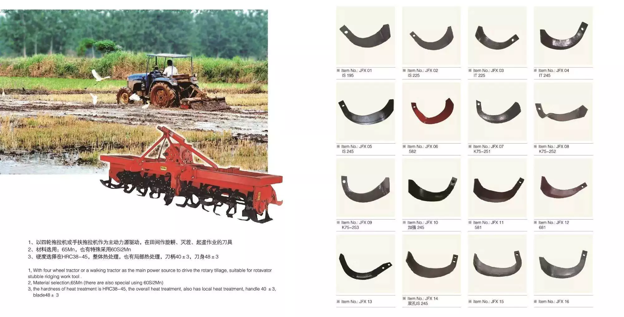
Agricultural machinery, also known as agricultural machinery, is any mechanical device or structure used in agriculture . It includes hand tools, tractors and countless other farm implements. Agricultural machinery can be divided into two categories: power tools and hand tools. Some of the most common types of agricultural equipment are listed below. Each of these categories includes parts used to repair, maintain, and operate a specific piece of equipment or machinery. To learn more about agricultural machinery, please visit the Manufacturers and Suppliers section of our website.
agriculturalparts

Agricultural Machinery

Agricultural machinery parts are critical to the overall operation of a farm or ranch. Replacement parts are essential if your equipment is not functioning as expected. CZPT’s consumables experts are ready to help you find the right replacement parts for your equipment. You can rely on our knowledgeable staff to provide you with fast and accurate replacement services. If your agricultural machinery needs replacement parts, please contact us for assistance.
Key drivers of the agricultural machinery market include high global demand for food, rapid crop production, access to resources, and availability of credit. Agricultural machinery is mainly manufactured in Europe, the United States, Japan and China. Overall, we expect the agricultural machinery market to exceed $118 billion by 2025. Additionally, agricultural machinery OEM components are expected to grow at a CAGR of 3.6% over the next five years.
Agricultural machinery accessories include accessories and accessories other than tractor accessories. Plows loosen the soil and kill surface vegetation, fertilizer spreaders apply fertilizer evenly, rakes agitate the soil, and seeders sow seeds. Other accessories include balers, which collect materials and bundle them into management packs. Transplanters are used to transplant plants from one location to another. It must be properly maintained to maximize its useful life.
Farm machinery accessories can be found in all types of farming. From sowing to harvesting, farm machinery equipment is necessary to help farmers in various agricultural activities. Without mechanization, farming would not be as profitable as it is today. In Iran, CZPT produces agricultural machinery parts including harrows, tillers, grain refiners, spinning machines and threshers. You can also find farm machinery accessories for sale through these companies.
A well-known brand in the field of agricultural machinery is CZPT. Parts can be found for CZPT and CZPT models. The company also produces replacement parts for many different models. The company’s extensive dealer network spans more than 160 countries. PDF also supplies agricultural machinery parts for brands such as Ford and CZPT. If you are looking for reliable quality and cost-effective agricultural machinery, we can get the parts you need from these brands.

Agricultural Equipment

Growing population and demand for equipment drive the demand for agricultural equipment in Asia. In countries with limited land such as India, low-paying agricultural jobs are not enough for many farmers. At the same time, Australia has a large amount of agricultural land, but the reduction of agricultural labor has led to the increasing mechanization and integration of agricultural production. This, in turn, has fueled a surge in demand for Australian agricultural products in Asia, particularly in China and India.
Tractor transplanter is a common agricultural equipment. Tractors pull on these machines, which dig holes and put plants into the holes. A cultivator is another type of agricultural equipment that tills the soil and controls weeds. Smaller operations often use a cultivator. Large plastic farms, on the other hand, need to invest in cladding, using a series of wheels to lay down a layer of plastic.
Agricultural machinery is widely used. For example, tractors can carry heavy agricultural attachments such as haymakers and grain turbines. Farm equipment also helps farmers prepare soil for growing and harvesting large quantities of crops. It also helps transport food to other regions for processing. These machines make farming easier and more efficient. With all these benefits, it’s no wonder so many people engage in farming as a profession. The world needs food and agriculture, and agricultural equipment is an integral part of the process.
Agricultural equipment operators use heavy agricultural machinery every day. They inspect the equipment and make minor repairs to keep it running smoothly. They also monitor the working environment and working conditions around the equipment. Depending on the field, agricultural equipment operators can operate a variety of agricultural equipment, load and unload products, and even harvest crops. These workers may spend most of the year working outdoors, which can take a long time. The average workweek for an agricultural equipment operator is approximately 18 hours.
Agricultural equipment operators often gain practical experience on the job. Some jobs in the industry may require a high school diploma, and students without a high school diploma can work on farms to learn the skills needed for the position. The industry requires employees to be properly trained and certified to operate equipment safely. AWS certification is highly recommended. All Associate of Applied Science in Agricultural Production Systems include core business and management courses applicable to the agricultural industry.
agriculturalparts

Agricultural machinery manufacturers

Agricultural machinery manufacturers produce agricultural implements such as tractors and combines for agricultural purposes. The production of these machines increases the productivity and efficiency of farmers around the world. These machines and parts increase the quality and quantity of crop production while reducing labor costs. They also help improve soil fertility. It’s important to choose the right type of machine for your farm because not all farm machinery is the same. There are many high-quality agricultural machinery manufacturers in China, whose prices are competitive with the local market prices.
The growth of the agricultural machinery market is mainly driven by the growing global food demand. Agricultural equipment manufacturers are investing in precision-based technologies, which allow them to build better agricultural machines. In addition, OEM parts manufacturers focus on the safety, quality and continuous improvement of agricultural machinery parts. With the shift in focus, the agricultural machinery market is expected to make great strides in the coming years. Along with these improvements, the demand for agricultural machinery OEM parts is expected to grow at an annual rate of over 3%.
CZPT Group: This agricultural machinery manufacturer has more than 20 overseas service centers around the world. The company is committed to providing excellent customer service and provides a warranty on all of its products. CZPT Machinery’s space parts are easily available at their service center. Shandong CZPT Heavy Industry International, a Chinese agricultural machinery manufacturer, was established in 1998 and is headquartered in Weifang City, Shandong Province.
Although the agricultural machinery industry is growing, the market is still affected by the economic downturn. The COVID-19 pandemic has put pressure on farming operations, who may forgo buying expensive equipment. Private investment in industrial equipment is also falling and is expected to decline further in 2020 and 2021. On the other hand, aftermarket agricultural machinery parts are tailored for an exact fit and outperform OEM parts.
agriculturalparts

Agricultural Machinery Suppliers

Agricultural Machinery Suppliers have a wide variety of products. From large farm machines to small ones, you’ll find it all in one place. In addition to providing first-class machinery, agricultural machinery suppliers can also provide you with spare parts. Shandong Heavy Industry International, for example, is China’s largest agricultural machinery maker, with annual sales of $9 billion. The company is headquartered in Weifang, Shandong and has been operating for more than six years.
Most farm equipment consists of hundreds of parts. For example, a typical tractor has more than 1,700 parts. Manufacturers have been shifting to just-in-time delivery of parts and raw materials. While the system works for predictable supply chains, it can break down when one component fails. Therefore, the best way to avoid problems and maximize profits is to get a list of Indian agricultural machinery suppliers through a dedicated marketplace.
Therefore, there are many suppliers of agricultural machinery. Some of the biggest names in the industry include CZPT and CZPT, both of which employ thousands of people. CZPT also offers a complete line of walk-behind and riding mowers, as well as log splitters and snow blowers. In addition, the German-made CZPT tractor line is being launched in Brazil. Finally, some smaller agricultural machinery enterprises produce and sell agricultural machinery.
In the next decade, the global agricultural machinery market will grow moderately. But in the short term, crop prices are expected to fall, which will negatively affect agricultural income and the agricultural machinery market. Experts predict that this will affect the demand for agricultural machinery. These factors will continue to influence the market and help farmers make better decisions. However, no single factor can guarantee that the agricultural machinery industry will not be affected by economic changes.
In addition to tractors, other types of agricultural machinery are also widely used for agricultural purposes. Tractors are the most common type of agricultural machinery and include rotary tillers, power tillers, subsoilers and trowels. Other equipment used for planting includes planters, planters and irrigation systems. Some specialized equipment includes sprinkler systems, micro sprinklers, and soil spray technology.

China OEM Custom High Precision CNC Machine Tools Machining Stainless Steel Brass Parts for Auto Agricultural Sewing Coffee Machinery     agricultural parts onlineChina OEM Custom High Precision CNC Machine Tools Machining Stainless Steel Brass Parts for Auto Agricultural Sewing Coffee Machinery     agricultural parts online
editor by czh 2022-12-29

China OEM Qingdao Ruilan Custom Die-Casting Part with Elbow Flange to Hose, Made of Die-Casting and Machine wholesaler

Product Description

Product Photos


Product Detail


Product Description

Type

Casting

Application

agriculture machinery\ construction machinery\ mining machinery and so on

Material

Gray cast iron, nodular cast iron,steel cast

Weight

1-500kg

Machine Tolerance

Controlled by ISO 2768-mk

Design Support

Auto CAD, Solid works, PDF

Casting Tolerance

CT10-13

Standard

ISO9001

Process

Casting + Machining + Zinc Plate

Service

OEM


 Product Process

Sand casting is a casting-based manufacturing process that involves the use of a sand mold. It’s used to create metal products and components in a variety of sizes and shapes. Half of all metal castings – about 60% – are produced using sand casting. Below, the steps of sand casting.

Sand preparation → mold making → core making → pouring → shaved sand  → daring processing → inspection


Other Casting parts

Quality Control

1.All specification is designed by professional engineers.

2.All material is processed by skilled workers and advanced CNC lathe.

3.All cylinders are 100% tested before package to ensure every cylinder is qualified for its purpose.

4.Package is air cushion film for each cylinder, and wooden case or steel pallet for all cylinders to ensure goods can arrive at customer safely.

5.One year warranty and long time track service is offered to solve any problems of after sale.

Packaging & Shipping 

1. Packing: Air cushion film+ Steel Pallet or Plywood Case or Carton


2. Shipping: By sea, By air, or By express.

About Company

HangZhou Ruilan specialize in OEM customize casting parts that used in agriculture machinery\ construction machinery\ mining machinery and so on.

Casting is a manufacturing process in which a liquid material is usually poured into a mold, which contains a hollow cavity of the desired shape, and then allowed to solidify. The solidified part is also known as a casting, which is ejected or broken out of the mold to complete the process. Casting materials are usually metals or various time setting materials that cure after mixing 2 or more components together; examples are epoxy, concrete, plaster and clay. Casting is most often used for making complex shapes that would be otherwise difficult or uneconomical to make by other methods.

We can offer OEM service,please offer us below data:

a. casting parts size:

b. casting parts material:

c. casting parts drawing:

d. the quantity of casting parts


Company Other Products


FAQ

 1. who are we?
We are based in ZheJiang , China, start from 2011,sell to South Asia(8.33%),Southern Europe(8.33%),Northern Europe(8.33%),Central America(8.33%),Western Europe(8.33%),Eastern Asia(8.33%),Mid East(8.33%),Africa(8.33%),Southeast Asia(8.33%),Eastern Europe(8.33%),South America(8.33%),North America(8.33%). There are total about 51-100 people in our office.

2. how can we guarantee quality?
Always a pre-production sample before mass production;
Always final Inspection before shipment;

3.what can you buy from us?
Welding Mathinery attachment and equipment, Hydraulic cylinder, Railway Casting,Railway wagon,steel casting,iron casting,Precision Casting

4. why should you buy from us not from other suppliers?
professional weding machinery attachment and equipment supplier, hydraulic cylinders,casting parts, welding parts, forging parts

5. what services can we provide?
Accepted Delivery Terms: FOB,CFR,CIF,EXW;
Accepted Payment Currency:USD;
Accepted Payment Type: T/T;
Language Spoken:English,Chinese,Russian

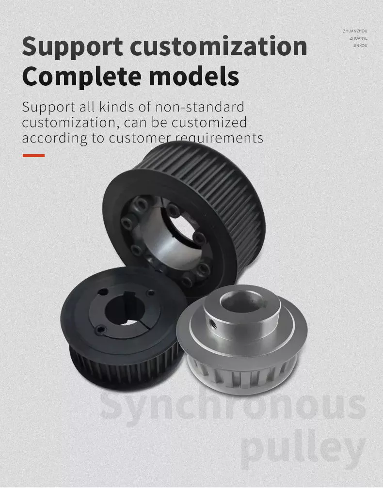
What Is a Pulley?

The pulley is a wheel mounted on a shaft or axle. Its purpose is to support the movement of a cable that is taut. This cable transfers power to a shaft. However, there are certain safety precautions that you should follow when using a pulley. Read on to learn more! Listed below are common uses and their main parts. Listed below are some of the benefits of using a pulley.
pulley

Common uses of a pulley

A pulley is a common mechanical device used to increase the force needed to lift a heavy object. Most commonly, these devices are used in construction equipment. These machines use high-10sion ropes to transfer heavy objects from 1 floor to another. Other common uses of a pulley include buckets and flagpoles. These devices are extremely useful in a wide range of applications. To learn more about the common uses of pulleys, keep reading.
A pulley is a wheel with grooves for holding rope. Its purpose is to change the direction and point at which a pulling force acts. It is usually used in sets to reduce the amount of force needed to lift a load, but the work involved is similar. Pulleys are also used in rock climbing devices. For many applications, a pulley is a vital part of construction.
The most common use of a pulley involves hoisting and lowering a flag. Other examples include clotheslines, bird feeders, and escalators. Pulleys are also commonly used on oil derricks. Many other common applications include hoisting and lowering garage doors. Pulley systems are also used in engines and cranes. For more information, check out our interactive pulley diagram!
Pulleys can also be used to lower total work required for a task. In many cases, a pulley will consist of 2 parts: the pulley hub and the shaft pulley. The hub clamps the shaft pulley, while the pulley itself is connected to the motor or other device. If you’re looking for a pulley, it’s important to learn how it works.
The most common uses for a pulley involve lifting heavy objects, and the mechanism used to lift them is known as a pulley. A pulley is an industrial device that uses 2 wheels to reduce the force needed to lift a weight. The pulley reduces this force by half by allowing the user to pull on the rope 4 times as far. The pulley also allows for a smaller lifting distance.

Main parts of a pulley

A pulley consists of the main element of a system. This is typically a cable, rope, belt, or chain. There are 2 basic types of pulleys – a Driver Pulley and a Follower Pulley. Pulleys are available in small and large sizes. The periphery part of the pulley is called the Face, and the protruding middle part is called the Crown. A pulley’s face can be round, rectangular, or even “V” shaped.
The first pulley was created by the Greek mathematician Archimedes in the third century BCE. These simple machines are made of a rope, an axle, and a wheel. The pulley’s end is attached to a person, object, or motor. These machines can be used in various tasks to lift heavy objects. The pulley is a great mechanical advantage for any lifter.
The ideal mechanical advantage of a pulley is defined by the number of rope segments that pull an object. The higher the number of loops on the rope, the higher the mechanical advantage. The greater the mechanical advantage, the less force is required to move the object. Likewise, the greater the distance the rope traverses, the higher the mechanical advantage of a pulley. There are several different types of pulley, depending on their combination of rope, wheel, and rope.
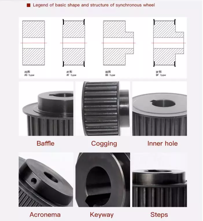
The basic components of a pulley are the face and hub, and the rope is threaded into the center of the pulley. The pulley is usually made of a rope and can be used to lift heavy weights. It can also be used to apply great force in any direction. Step pulleys have multiple faces, which are fixed in sequence. They can also increase the speed of the driven pulley.
A pulley is a simple machine consisting of a wheel, rope, or chain. These parts are crucial for making moving and lifting easier. Because they change the direction and magnitude of force, they can be a useful tool. Some pulleys even change direction. You can learn more about the pulley by downloading this resource today. The resources are designed to support the new 9-1 GCSEs in Design & Technology and Engineering.
pulley

Mechanical advantage

Pulleys have been used to move heavy objects for centuries. When 2 rope sections are used, the weight of a 100kg mass can be moved with only 500 newtons of force. Adding an extra pulley increases the mechanical advantage. If the pulley has 2 wheels, the distance between the rope sections and the wheel grooves is only half the distance, but the mechanical advantage still applies. Adding another pulley increases the mechanical advantage, but can be risky.
Mechanical advantage is the ratio of force used versus force applied. The calculations are made under the assumption that the ropes and weights do not elongate or lose energy due to friction. If the weights are very light, the mechanical advantage is greater than that in the real world. To calculate the mechanical advantage, the weight of the load to be lifted must be the same as the weight of the person using the pulley.
A single moveable pulley has a mechanical advantage of two. The weight passes around the pulley, and 1 end of the rope is attached to a fixed point. The pulling force is then applied to the other end of the rope. The distance the weight travels doubles, or halved, depending on the direction of the pulley. Adding a second pulley reduces the distance and the effort required to lift it.
There are several ways to calculate the mechanical advantage of a pulley system. Some methods are specific to certain types of systems, while others work for all systems. The T-Method is a good choice in many applications, as it calculates the units of tension for each rope segment. Once you have determined the input force, you need to determine the maximum force that will be applied to each component. A compound pulley, for example, will require 4 units of tension for each rope segment.
In simple terms, the effort is the amount of force needed to lift the load. This force is measured in newtons (N). A mechanical advantage is often presented without units. If the student does not have this unit, you may need to convert the units to newtons, since 1 kilogram is equal to 10 newtons. If you can’t figure out the units of effort, you can use the KWL chart provided by the teacher.
pulley

Safety precautions

There are a few safety precautions you should take when using a pulley. First, always check the SWL (safe working load) before attaching anything to the pulley. This indicates the maximum weight and angle the pulley can safely handle. Second, make sure that your work area is free from people and debris. Third, wear a hard hat to protect your head from blows and falling objects.
Another important consideration is anchoring. Although the pulley reduces the weight of an object, it is not enough to eliminate the weight. This is especially true if you are hoisting a heavy object, such as a motorcycle or lawnmower. It is important to ensure that the anchoring point can support the entire weight of the load. It is also important to follow proper anchoring procedures when using a pulley to lift a motorcycle or lawnmower.
In addition to the safety latch, you should use a tag line to control the suspended load. Remember that a chain pulley block is necessary for vertical lifting. You should also wear personal protective equipment (PPE) while using a pulley to avoid injuries. If your workplace does not have an PPE policy, you should consider implementing a similar policy. These safety guidelines are a good start.
If you are using a pulley to lift heavy objects, make sure to wear gloves. Those who are not familiar with rope-pulling will have an easier time demonstrating how it works. If you are using a rope-pulley system in a classroom, be sure to follow lab safety guidelines. Wear cloth gloves, clear the area, and do not jerk the rope. In addition, never allow yourself to be pulled into the rope by an unfamiliar person.
Another important safety precaution when using a pulley is to ensure that the anchor point for your system is adequate to support the weight of the object being lifted. Check with the manufacturer of the pulley to find out what its weight limit is, as some types of pulleys are designed to lift much heavier weights than others. It is important to follow all manufacturer’s instructions when using a pulley.

China OEM Qingdao Ruilan Custom Die-Casting Part with Elbow Flange to Hose, Made of Die-Casting and Machine     wholesaler China OEM Qingdao Ruilan Custom Die-Casting Part with Elbow Flange to Hose, Made of Die-Casting and Machine     wholesaler

China Standard Custom CNC Milling Machine Lathe Spare Auto Motor Motorcycle Turning Engine Metal Brass Copper Steel Aluminum Part near me manufacturer

Product Description

Basic Info
 

Surface treatment  polishing, chrome plating, zinc plating, nickel plating, clear/black anodizing, Black, Nitrogenation, sandblasting,  powder coating, etc.
Heat Treatment Nitride, Hardening etc.
Machining Equipment CNC Machining Center, CNC Turning Machine, CNC Milling Machine, Surface Grinders, Wire Cutting Machine,Electrical Discharge Machine,Drilling Machine, Rolling Machine
 
 
 Quality We have kind of measuring equipment like Coordinate Measuring Machine to check the pecision for the parts, and we will also make full protect for package for shipping. High Precision quality as drawing request will be provided.
 
Application Heavy industrial machinery, automation equipment, vehicles, package machines, food processing machines, agricultural machines, electronic machines, etc
Lead Time According to the quantity and drawings’ difficulties of clients
Trade Terms EXW, FOB, CIF, DAP.etc
Drawing Format . pdf / .dwg / .igs / .stp etc.

FAQ

Q1: Are you a trading company or a manufacturer? Location?
A1: We are a factory located in Bao’an, HangZhou, China.

Q2: Is there any MOQ required?
A2: No, there is no MOQ required, even 1 piece we can also process. 

Q3: How to ensure the quality of every process?
A3: The part will be checked when each process is finished, which makes sure there are no defects on the customers’ end.

Q4: How can I get the quotation?
A4: We will offer you the quotation within 12 working hours after receiving your detailed information. In order to quote you faster and more accurate, please provide us with the following information together with your inquiry:
1) CAD or 3D Drawings
2) Tolerance.
3) Material requirement
4) Surface treatment
5) Quantity (per order/per month/annual)
6) Any special demands or requirements, such as packing, labels, delivery, etc.

Q5: How do you make sure my drawings are confidential?
A5: we will keep them well and not release them to others without your permission. NDA can be also signed, if you needed.

Q6: Why choose HangZhou XYX Precision Co., Ltd?
A6:  1. Years of experience, which can offer you tailored solutions to your projects.
        2. Flexibility in lead time.
        3. Assurance in high-quality parts.


What Is a Pulley?

The pulley is a wheel mounted on a shaft or axle. Its purpose is to support the movement of a cable that is taut. This cable transfers power to a shaft. However, there are certain safety precautions that you should follow when using a pulley. Read on to learn more! Listed below are common uses and their main parts. Listed below are some of the benefits of using a pulley.
pulley

Common uses of a pulley

A pulley is a common mechanical device used to increase the force needed to lift a heavy object. Most commonly, these devices are used in construction equipment. These machines use high-10sion ropes to transfer heavy objects from 1 floor to another. Other common uses of a pulley include buckets and flagpoles. These devices are extremely useful in a wide range of applications. To learn more about the common uses of pulleys, keep reading.
A pulley is a wheel with grooves for holding rope. Its purpose is to change the direction and point at which a pulling force acts. It is usually used in sets to reduce the amount of force needed to lift a load, but the work involved is similar. Pulleys are also used in rock climbing devices. For many applications, a pulley is a vital part of construction.
The most common use of a pulley involves hoisting and lowering a flag. Other examples include clotheslines, bird feeders, and escalators. Pulleys are also commonly used on oil derricks. Many other common applications include hoisting and lowering garage doors. Pulley systems are also used in engines and cranes. For more information, check out our interactive pulley diagram!
Pulleys can also be used to lower total work required for a task. In many cases, a pulley will consist of 2 parts: the pulley hub and the shaft pulley. The hub clamps the shaft pulley, while the pulley itself is connected to the motor or other device. If you’re looking for a pulley, it’s important to learn how it works.
The most common uses for a pulley involve lifting heavy objects, and the mechanism used to lift them is known as a pulley. A pulley is an industrial device that uses 2 wheels to reduce the force needed to lift a weight. The pulley reduces this force by half by allowing the user to pull on the rope 4 times as far. The pulley also allows for a smaller lifting distance.

Main parts of a pulley

A pulley consists of the main element of a system. This is typically a cable, rope, belt, or chain. There are 2 basic types of pulleys – a Driver Pulley and a Follower Pulley. Pulleys are available in small and large sizes. The periphery part of the pulley is called the Face, and the protruding middle part is called the Crown. A pulley’s face can be round, rectangular, or even “V” shaped.
The first pulley was created by the Greek mathematician Archimedes in the third century BCE. These simple machines are made of a rope, an axle, and a wheel. The pulley’s end is attached to a person, object, or motor. These machines can be used in various tasks to lift heavy objects. The pulley is a great mechanical advantage for any lifter.
The ideal mechanical advantage of a pulley is defined by the number of rope segments that pull an object. The higher the number of loops on the rope, the higher the mechanical advantage. The greater the mechanical advantage, the less force is required to move the object. Likewise, the greater the distance the rope traverses, the higher the mechanical advantage of a pulley. There are several different types of pulley, depending on their combination of rope, wheel, and rope.
The basic components of a pulley are the face and hub, and the rope is threaded into the center of the pulley. The pulley is usually made of a rope and can be used to lift heavy weights. It can also be used to apply great force in any direction. Step pulleys have multiple faces, which are fixed in sequence. They can also increase the speed of the driven pulley.
A pulley is a simple machine consisting of a wheel, rope, or chain. These parts are crucial for making moving and lifting easier. Because they change the direction and magnitude of force, they can be a useful tool. Some pulleys even change direction. You can learn more about the pulley by downloading this resource today. The resources are designed to support the new 9-1 GCSEs in Design & Technology and Engineering.
pulley

Mechanical advantage

Pulleys have been used to move heavy objects for centuries. When 2 rope sections are used, the weight of a 100kg mass can be moved with only 500 newtons of force. Adding an extra pulley increases the mechanical advantage. If the pulley has 2 wheels, the distance between the rope sections and the wheel grooves is only half the distance, but the mechanical advantage still applies. Adding another pulley increases the mechanical advantage, but can be risky.
Mechanical advantage is the ratio of force used versus force applied. The calculations are made under the assumption that the ropes and weights do not elongate or lose energy due to friction. If the weights are very light, the mechanical advantage is greater than that in the real world. To calculate the mechanical advantage, the weight of the load to be lifted must be the same as the weight of the person using the pulley.
A single moveable pulley has a mechanical advantage of two. The weight passes around the pulley, and 1 end of the rope is attached to a fixed point. The pulling force is then applied to the other end of the rope. The distance the weight travels doubles, or halved, depending on the direction of the pulley. Adding a second pulley reduces the distance and the effort required to lift it.
There are several ways to calculate the mechanical advantage of a pulley system. Some methods are specific to certain types of systems, while others work for all systems. The T-Method is a good choice in many applications, as it calculates the units of tension for each rope segment. Once you have determined the input force, you need to determine the maximum force that will be applied to each component. A compound pulley, for example, will require 4 units of tension for each rope segment.
In simple terms, the effort is the amount of force needed to lift the load. This force is measured in newtons (N). A mechanical advantage is often presented without units. If the student does not have this unit, you may need to convert the units to newtons, since 1 kilogram is equal to 10 newtons. If you can’t figure out the units of effort, you can use the KWL chart provided by the teacher.
pulley

Safety precautions

There are a few safety precautions you should take when using a pulley. First, always check the SWL (safe working load) before attaching anything to the pulley. This indicates the maximum weight and angle the pulley can safely handle. Second, make sure that your work area is free from people and debris. Third, wear a hard hat to protect your head from blows and falling objects.
Another important consideration is anchoring. Although the pulley reduces the weight of an object, it is not enough to eliminate the weight. This is especially true if you are hoisting a heavy object, such as a motorcycle or lawnmower. It is important to ensure that the anchoring point can support the entire weight of the load. It is also important to follow proper anchoring procedures when using a pulley to lift a motorcycle or lawnmower.
In addition to the safety latch, you should use a tag line to control the suspended load. Remember that a chain pulley block is necessary for vertical lifting. You should also wear personal protective equipment (PPE) while using a pulley to avoid injuries. If your workplace does not have an PPE policy, you should consider implementing a similar policy. These safety guidelines are a good start.
If you are using a pulley to lift heavy objects, make sure to wear gloves. Those who are not familiar with rope-pulling will have an easier time demonstrating how it works. If you are using a rope-pulley system in a classroom, be sure to follow lab safety guidelines. Wear cloth gloves, clear the area, and do not jerk the rope. In addition, never allow yourself to be pulled into the rope by an unfamiliar person.
Another important safety precaution when using a pulley is to ensure that the anchor point for your system is adequate to support the weight of the object being lifted. Check with the manufacturer of the pulley to find out what its weight limit is, as some types of pulleys are designed to lift much heavier weights than others. It is important to follow all manufacturer’s instructions when using a pulley.

China Standard Custom CNC Milling Machine Lathe Spare Auto Motor Motorcycle Turning Engine Metal Brass Copper Steel Aluminum Part     near me manufacturer China Standard Custom CNC Milling Machine Lathe Spare Auto Motor Motorcycle Turning Engine Metal Brass Copper Steel Aluminum Part     near me manufacturer

China wholesaler CZPT CZPT Machine Parts CZPT PAM Precision Correction Material KA-9898 K53050 with Free Design Custom

Product Description

Fuji CZPT machine parts CZPT PAM precision correction material KA-9898 K53050
 

Description: FUJI CZPT PAM precision correction material
Part No: KA-9898
Condition: original new
Applicable models: KA-9898
Payment Term: T/T, Paypal, Westernunion are all allowed.
Lead time: in stock!

We also supply following CZPT spare parts:

FUJI XPF NOZZLE 0.4MM/0.7MM 1.MM/1.3MM/1.8MM/2.5MM/3.7MM/5.0MM 
FUJI XP142/XP143 NOZZLE 0.4MM/0.7MM/1.0MM/1.3MM/ 1.8MM/2.5MM /3.7MM/5.0MM 
FUJI XP T1065Z
FUJI XP142/XP143 S40159
XP243E DNSY3732/DNSY3731
FUJI XP142/XP143 PISTON AGDFPH8014
FUJI XP142/XP143 BODY ADNPH8810
FUJI XP142 CV-A1 (K1312A)
FUJI XP143 Z Q R  DNEH7042
FUJI XP142 Z Q R  DNEH7571
FUJI XP142/XP143  pin DNH8171       
FUJI XP142/XP143 pin DNPH8181
FUJI XP142/XP143 W1200-363PGX-C5Z
FUJI XP242XP243 DEEM5462/DEEM5461
FUJI XP142XP143 DEEM5391/DEEM5392
FUJI XP CXSM10-K6869-35,CXSL10-2-DCJ4481J
FUJI XP242/243 GFSY3310 W2515-235PGK-C5Z
FUJI XP242/XP243 H1007G:VKBH12R;H1007D:VKBH12W
FUJI XP242 DNSY3902 W2513-252PGX-C5Z
FUJI XP242/XP243  SGMAS-04A2A-FJ21
FUJI XP242/XP243 SGMAS-01A2A-FJ31
FUJI XP242/XP243 H4591T
FUJI XP242/XP243 DNSY3731
FUJI XP242/XP243 ADETR8066
FUJI XP242/XP243  XC-HR50 K1131F
FUJI XP242/XP243  VQZ312-5L1-C8
FUJI XP242/XP243   ADEGC8311
FUJI XP242/XP243   ADNAJ8310
FUJI XP142/XP143/XPF STOPPEP DNPH2100  
FUJI XP/QP/IP FEEDER 8MM/12MM/16MM/24MM/32MM/44MM 56MM/72MM/88MM

The responsibility of our enterprise:

1.We have always been adhering to the “quality of survival, quality tree brand, quality and efficiency, quality to promote development” quality policy
2.We always adhere to the premise of ensuring the quality of customer production, reduce customer production costs.
3.Unremittingly to the needs of our customers for the direction of our work.

Our business scope:

1.Nozzles, Feeders, Feeder Parts, cutters, filters, belts, motors, valves, sensors, camera, board cards and other machine parts…
2.Feeder Calibration Jigs, Feeder Storage Carts, IC Tray feeders, Stick feeders, Feeder Loading Unit,
3.Printer squeegee holder/blade, Clamp foil and other Printer Parts.
4.ESD splice tape, tool, stencil clean wiper/paper, PCB Magazine…
5.CZPT Peripheral equipment (PCB Separator, Solder paste mixer, Automatic SMD Chip Counter, etc… )
6.CZPT product recycling (feeder nozzle used machine…)                  

Terms of Payment:
     
        T/T, PayPal, Western Union

Our Advantages:

  1.  High quality and low cost. 
  2. Original new and copy new all available.
  3. Ship to worldwide.
  4. 10 years trading experience.
  5. Various brands available.
  6. Special type is available.

Contact us:
contact-info.html
 
Website: smtpartssupply

Three basic types of pulleys, their applications and ideal mechanical advantages

There are 3 basic types of pulleys: movable, fixed and compound. Each has its advantages and disadvantages, and you should be able to judge which type is best for your needs by looking at the table below. Once you have mastered the different types of pulleys, you can choose the right pulley for your next project. Now that you have mastered the 3 basic types, it is time to understand their applications and ideal mechanical advantages.
pulley

describe

The stress characteristics of a pulley depend on its size and construction. These stresses are derived by comparing the stress characteristics of different pulley designs. Stress criteria include static and fatigue strength analyses and specify maximum stress ranges. Stresses are calculated in a 3D stress field, including radial, tangential and axial stresses. The stress characteristics of pulleys are critical to the design and manufacture of industrial machines.
The principal stresses on the pulley shell are distributed in the tangential and hoop directions, close to the centerline of the pulley. If the pulley has a wide face, the axial stress occurring near the shell/disk junction can be large. The stress distribution was determined using British Standard BS5400 Part 10: Stresses at the shell and end disc connections for infinite fatigue life.
Another type of composite is a pulley with a belt section. Such structures are well known in the art. The corresponding help chapters for these elements contain detailed descriptions of the internal structure of these components. Chamfers between pulleys can also be defined using multiple tapers, with a smaller taper extending from midpoint 44 to large diameter 42. Additionally, the pulley can have multiple taper angles, and as the pulley moves away, the taper angle is from the center.

type

A pulley system uses a rope to move the object and 1 side of the rope to lift the load. The load is attached to 1 end of the pulley, while the other end can move freely in space. The force applied to the free end of the rope pulls the load up or down. Because of this, the mechanical advantage of the movable pulley is 2 to one. The greater the force applied to the free end of the rope, the greater the amount of movement achieved.
There are 3 common types of pulleys. The cast-iron variety has a rim at the front and a hub at the back. The arms of the pulley can be straight or curved. When the arms contract and yield instead of breaking, they are in tension. The top of the pulley centers the belt in motion and is available in widths ranging from 9mm to 300mm.
The rope, hub and axle are mounted on the pulley. They are common and versatile mechanical devices that make it easier to move or lift objects. Some pulleys change the direction of the force. Others change the magnitude. All types of pulleys can be used for a variety of different applications. Here are some examples. If you’re not sure which type to choose, you can find more resources online.
pulley

application

The applications for pulleys are almost limitless. This simple machine turns complex tasks into simple ones. They consist of a rope or chain wrapped around a wheel or axle. Using ropes, 1 can lift heavy objects without the enormous physical exertion of traditional lifting equipment. Some pulleys are equipped with rollers, which greatly magnifies the lifting force.
When used properly, the pulley system can change the direction of the applied force. It provides a mechanical advantage and allows the operator to remain separate from heavy objects. They are also inexpensive, easy to assemble, and require little lubrication after installation. Also, once installed, the pulley system requires little maintenance. They can even be used effortlessly. Despite having many moving parts, pulley systems do not require lubrication, making them a cost-effective alternative to mechanical lifts.
Pulleys are used in many applications including adjustable clotheslines in different machines, kitchen drawers and motor pulleys. Commercial users of pulley systems include cranes. These machines use a pulley system to lift and place heavy objects. They are also used by high-rise building washing companies. They can easily move a building without compromising its structural integrity. As a result, many industries rely on technology to make elevators easier.

Ideal mechanical advantage

The ideal mechanical advantage of a pulley system is the result of rope tension. The load is pulled to the center of the pulley, but the force is evenly distributed over the cable. Two pulleys will provide the mechanical advantage of 2 pulleys. The total energy used will remain the same. If multiple pulleys are used, friction between pulleys and pulleys reduces the return of energy.
Lever-based machines are simple devices that can work. These include levers, wheels and axles, screws, wedges and ramps. Their ability to work depends on their efficiency and mechanical superiority. The ideal mechanical advantage assumes perfect efficiency, while the actual mechanical advantage takes friction into account. The distance traveled by the load and the force applied are also factors in determining the ideal mechanical advantage of the pulley.
A simple pulley system has an MA of two. The weight attached to 1 end of the rope is called FA. Force FE and load FL are connected to the other end of the rope. The distance that the lifter pulls the rope must be twice or half the force required to lift the weight. The same goes for side-by-side pulley systems.

Materials used in manufacturing

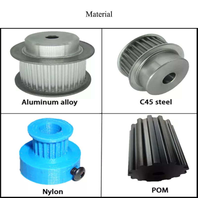
While aluminum and plastic are the most common materials for making pulleys, there are other materials to choose from for your timing pulleys. Despite their different physical properties, they all offer similar benefits. Aluminum is dense and corrosion-resistant, and plastic is lightweight and durable. Stainless steel is resistant to stains and rust, but is expensive to maintain. For this reason, aluminum is a popular choice for heavy duty pulleys.
Metal can also be used to make pulleys. Aluminum pulleys are lightweight and strong, while other materials are not as durable. CZPT produces aluminium pulleys, but can also produce other materials or special finishes. The list below is just representative of some common materials and finishes. Many different materials are used, so you should discuss the best options for your application with your engineer.
Metals such as steel and aluminum are commonly used to make pulleys. These materials are relatively light and have a low coefficient of friction. Steel pulleys are also more durable than aluminum pulleys. For heavier applications, steel and aluminum are preferred, but consider weight limitations when selecting materials. For example, metal pulleys can be used in electric motors to transmit belt motion.
pulley

cost

Replacing a tensioner in a car’s engine can cost anywhere from $90 to $300, depending on the make and model of the car. Cost can also be affected by the complexity of the pulley system and how many pulleys are required. Replacement costs may also increase depending on the severity of the damage. The cost of replacing pulleys also varies from car to car, as different manufacturers use different engines and drivetrains.
Induction motors have been an industrial workhorse for 130 years, but their cost is growing. As energy costs rise and the cost of ownership increases, these motors will only get more expensive. New technologies are now available to increase efficiency, reduce costs and improve safety standards.
The average job cost to replace an idler varies from $125 to $321, including labor. Parts and labor to replace a car pulley can range from $30 to $178. Labor and parts can cost an additional $10 to $40, depending on the make and model of the car. But the labor is worth the money because these pulleys are a critical part of a car’s engine.

China wholesaler CZPT CZPT Machine Parts CZPT PAM Precision Correction Material KA-9898 K53050     with Free Design CustomChina wholesaler CZPT CZPT Machine Parts CZPT PAM Precision Correction Material KA-9898 K53050     with Free Design Custom

China factory Custom CZPT Aluminium Die Casting CZPT Die Casting Die Fitting Moulds Toy CZPT Washing Machine CZPT Pet Preform CZPT Auto Car Cycles and Parts Auto Parts with Free Design Custom

Product Description

Product Description


Product name High Pressure Die Casting Mold
Mould Material H13, DIEVAR,SKD61, 8407, 8418, 1.2343,1.2344,1.2367,3Cr2W8V, 4Cr5MoSiV, W400, DAC55, DH-31, etc
Casting Alloy Aluminum, Magnesium
Cavity Qty Single Cavity, Multiple Cavity or Unit Cavity
Tonnage 200T-4400T
Treatment Heat Treatment, Nitriding, Polishing etc.
Mold Life 50,000 to 300,000 depend on products
Applications 1. Automobile and motorcycle parts;
2. Telecom Parts;
3. Electrical appliance parts;
4. Lights & lamps parts;
5. Industrial hardware and Machine Sparepart;
6. Household Appliance parts;
7. Medical Instrument parts;
Lead Time 35-60 days
Special request According to customer’s request


Our Advantages


1)

Around 20 years mold making experience, certificated with IS09001 & IATF 16949 and with skilled and professional workers. We are the expert at Strong engineering, exquisite workmanship, products of various materials high precision request and complex shapes;
2) More than 30 countries export experience ensure our technical team are CZPT to offer tailor-made service with International standard towards to our customers;
3) We are big company group investing a lot on hardware and software facilities. We have advanced and high precision equipment and machines as well as latest mold design software and mold flow analysis software;
4) Work with many world class Japanese brands, sound & rigorous Japanese management and quality control system.Very high quality in the industry;
5) Direct export to be sure cost-effective and competitive. For some mature molds,we are 20-30% cheaper than others;
6) Three factories guarantee our plenty production capacity and our short lead time and quick response capability;
7) Familiar with material industry, to use  high quality materials to be sure long life time and excellent hot runner system and cooling system to increase production efficiency;


Mold & molding parts we made


Patents Awards Certificates

Global customers & Exhibition

Company Profile

About Us:

As the professional tooling & Die making company group in China, Symbos has 3 manufacturing bases, 2 in ZheJiang and 1 in HangZhou. We can provide customers with products and services which not only meet their requirements in quality products but surpass their expectations each time. We pride ourselves in offering customers bespoke services at every stage.

Symbos provides professional mould, CZPT components, injection moulding and CNC machining for domestic as well as oversea companies. A certain number of products have been exported to Japan, Germany, USA, Canada, Italy, Spain, India, Thailand and other countries. We work with the world-class brands like Toyota, Nissan, Arcelik, Simens, BMW, Philips, AISIN, etc.

Symbos works with a diverse range of customers from a variety of industry sectors, included but not limited to: Automotive,, home appliances, electronics products, house-hold goods, consumer products and small precision parts. Based on innovation and investment in advanced equipment and economically attractive concepts, we are successful in not only high-end die casting die but als low cost plastic injection mold.

For die casting mold, 90% is automotive sector. For plastic injection mold, we are strong on electronics products, home appliances (MDA& SDA), house-hold goods, insert molding, over molding and precision parts like caps and connector. We provide plastic injection mold as well as plastic molding parts.

Punctuality and know-how, dedication and skilled people are the solid basis for our many years of successful operation.
Innovation and investment in advanced equipment and new applications are the driving forces for the common success.

We expect to work with your esteemed company to realize mutual growth!

Packaging & Shipping


Q&A:

Q1. Do you provide OEM Service?
A: Yes, we provide OEM Service.
Q2.  What do I need to provide if I want to customize products and get a offer?
A:  Pls send 2D or 3D drawing(.step/.stp/.igs/.dwg is prefer) or samples and detailed requirement.
Q3.  What’s the process of Customized product?
A:1. Mold design from product drawings or samples. 2. Confirm the drawings with customer. 3. Make mold.  4. T1 test and send samples to customer for adjustment. 5. Adjust mold and retest and send samples to customer for approval. 7. Receive confirmation from customer. 8.Send out mold or arrange series production.
Q4: What if I got some defective mold/products?
A: We will take full responsibility for our defaulty. We will implement the fastest remedy to rework or to reproduce on our account. As for parts, will exchange good products or refund you immediately. If you have any questions, please feel free to contact us.
 

The Benefits of Spline Couplings for Disc Brake Mounting Interfaces

Spline couplings are commonly used for securing disc brake mounting interfaces. Spline couplings are often used in high-performance vehicles, aeronautics, and many other applications. However, the mechanical benefits of splines are not immediately obvious. Listed below are the benefits of spline couplings. We’ll discuss what these advantages mean for you. Read on to discover how these couplings work.

Disc brake mounting interfaces are splined

There are 2 common disc brake mounting interfaces – splined and six-bolt. Splined rotors fit on splined hubs; six-bolt rotors will need an adapter to fit on six-bolt hubs. The six-bolt method is easier to maintain and may be preferred by many cyclists. If you’re thinking of installing a disc brake system, it is important to know how to choose the right splined and center lock interfaces.
splineshaft

Aerospace applications

The splines used for spline coupling in aircraft are highly complex. While some previous researches have addressed the design of splines, few publications have tackled the problem of misaligned spline coupling. Nevertheless, the accurate results we obtained were obtained using dedicated simulation tools, which are not commercially available. Nevertheless, such tools can provide a useful reference for our approach. It would be beneficial if designers could use simple tools for evaluating contact pressure peaks. Our analytical approach makes it possible to find answers to such questions.
The design of a spline coupling for aerospace applications must be accurate to minimize weight and prevent failure mechanisms. In addition to weight reduction, it is necessary to minimize fretting fatigue. The pressure distribution on the spline coupling teeth is a significant factor in determining its fretting fatigue. Therefore, we use analytical and experimental methods to examine the contact pressure distribution in the axial direction of spline couplings.
The teeth of a spline coupling can be categorized by the type of engagement they provide. This study investigates the position of resultant contact forces in the teeth of a spline coupling when applied to pitch diameter. Using FEM models, numerical results are generated for nominal and parallel offset misalignments. The axial tooth profile determines the behavior of the coupling component and its ability to resist wear. Angular misalignment is also a concern, causing misalignment.
In order to assess wear damage of a spline coupling, we must take into consideration the impact of fretting on the components. This wear is caused by relative motion between the teeth that engage them. The misalignment may be caused by vibrations, cyclical tooth deflection, or angular misalignment. The result of this analysis may help designers improve their spline coupling designs and develop improved performance.
CZPT polyimide, an abrasion-resistant polymer, is a popular choice for high-temperature spline couplings. This material reduces friction and wear, provides a low friction surface, and has a low wear rate. Furthermore, it offers up to 50 times the life of metal on metal spline connections. For these reasons, it is important to choose the right material for your spline coupling.
splineshaft

High-performance vehicles

A spline coupler is a device used to connect splined shafts. A typical spline coupler resembles a short pipe with splines on either end. There are 2 basic types of spline coupling: single and dual spline. One type attaches to a drive shaft, while the other attaches to the gearbox. While spline couplings are typically used in racing, they’re also used for performance problems.
The key challenge in spline couplings is to determine the optimal dimension of spline joints. This is difficult because no commercial codes allow the simulation of misaligned joints, which can destroy components. This article presents analytical approaches to estimating contact pressures in spline connections. The results are comparable with numerical approaches but require special codes to accurately model the coupling operation. This research highlights several important issues and aims to make the application of spline couplings in high-performance vehicles easier.
The stiffness of spline assemblies can be calculated using tooth-like structures. Such splines can be incorporated into the spline joint to produce global stiffness for torsional vibration analysis. Bearing reactions are calculated for a certain level of misalignment. This information can be used to design bearing dimensions and correct misalignment. There are 3 types of spline couplings.
Major diameter fit splines are made with tightly controlled outside diameters. This close fit provides concentricity transfer from the male to the female spline. The teeth of the male spline usually have chamfered tips and clearance with fillet radii. These splines are often manufactured from billet steel or aluminum. These materials are renowned for their strength and uniform grain created by the forging process. ANSI and DIN design manuals define classes of fit.
splineshaft

Disc brake mounting interfaces

A spline coupling for disc brake mounting interfaces is a type of hub-to-brake-disc mount. It is a highly durable coupling mechanism that reduces heat transfer from the disc to the axle hub. The mounting arrangement also isolates the axle hub from direct contact with the disc. It is also designed to minimize the amount of vehicle downtime and maintenance required to maintain proper alignment.
Disc brakes typically have substantial metal-to-metal contact with axle hub splines. The discs are held in place on the hub by intermediate inserts. This metal-to-metal contact also aids in the transfer of brake heat from the brake disc to the axle hub. Spline coupling for disc brake mounting interfaces comprises a mounting ring that is either a threaded or non-threaded spline.
During drag brake experiments, perforated friction blocks filled with various additive materials are introduced. The materials included include Cu-based powder metallurgy material, a composite material, and a Mn-Cu damping alloy. The filling material affects the braking interface’s wear behavior and friction-induced vibration characteristics. Different filling materials produce different types of wear debris and have different wear evolutions. They also differ in their surface morphology.
Disc brake couplings are usually made of 2 different types. The plain and HD versions are interchangeable. The plain version is the simplest to install, while the HD version has multiple components. The two-piece couplings are often installed at the same time, but with different mounting interfaces. You should make sure to purchase the appropriate coupling for your vehicle. These interfaces are a vital component of your vehicle and must be installed correctly for proper operation.
Disc brakes use disc-to-hub elements that help locate the forces and displace them to the rim. These elements are typically made of stainless steel, which increases the cost of manufacturing the disc brake mounting interface. Despite their benefits, however, the high braking force loads they endure are hard on the materials. Moreover, excessive heat transferred to the intermediate elements can adversely affect the fatigue life and long-term strength of the brake system.

China factory Custom CZPT Aluminium Die Casting CZPT Die Casting Die Fitting Moulds Toy CZPT Washing Machine CZPT Pet Preform CZPT Auto Car Cycles and Parts Auto Parts     with Free Design CustomChina factory Custom CZPT Aluminium Die Casting CZPT Die Casting Die Fitting Moulds Toy CZPT Washing Machine CZPT Pet Preform CZPT Auto Car Cycles and Parts Auto Parts     with Free Design Custom

China Best Sales New Custom CNC Turning Milling Machine Component Metal Steel Aluminum CNC Precision Machining Part for Vehicle Auto Engine near me factory

Product Description

Basic Info
 

Surface treatment  polishing, chrome plating, zinc plating, nickel plating, clear/black anodizing, Black, Nitrogenation, sandblasting,  powder coating, etc.
Heat Treatment Nitride, Hardening etc.
Machining Equipment CNC Machining Center, CNC Turning Machine, CNC Milling Machine, Surface Grinders, Wire Cutting Machine,Electrical Discharge Machine,Drilling Machine, Rolling Machine
 
 
 Quality We have kind of measuring equipment like Coordinate Measuring Machine to check the pecision for the parts, and we will also make full protect for package for shipping. High Precision quality as drawing request will be provided.
 
Application Heavy industrial machinery, automation equipment, vehicles, package machines, food processing machines, agricultural machines, electronic machines, etc
Lead Time According to the quantity and drawings’ difficulties of clients
Trade Terms EXW, FOB, CIF, DAP.etc
Drawing Format . pdf / .dwg / .igs / .stp etc.

FAQ

Q1: Are you a trading company or a manufacturer? Location?
A1: We are a factory located in Bao’an, HangZhou, China.

Q2: Is there any MOQ required?
A2: No, there is no MOQ required, even 1 piece we can also process. 

Q3: How to ensure the quality of every process?
A3: The part will be checked when each process is finished, which makes sure there are no defects on the customers’ end.

Q4: How can I get the quotation?
A4: We will offer you the quotation within 12 working hours after receiving your detailed information. In order to quote you faster and more accurate, please provide us with the following information together with your inquiry:
1) CAD or 3D Drawings
2) Tolerance.
3) Material requirement
4) Surface treatment
5) Quantity (per order/per month/annual)
6) Any special demands or requirements, such as packing, labels, delivery, etc.

Q5: How do you make sure my drawings are confidential?
A5: we will keep them well and not release them to others without your permission. NDA can be also signed, if you needed.

Q6: Why choose HangZhou XYX Precision Co., Ltd?
A6:  1. Years of experience, which can offer you tailored solutions to your projects.
        2. Flexibility in lead time.
        3. Assurance in high-quality parts.


Helical, Straight-Cut, and Spiral-Bevel Gears

If you are planning to use bevel gears in your machine, you need to understand the differences between Helical, Straight-cut, and Spiral bevel gears. This article will introduce you to these gears, as well as their applications. The article will also discuss the benefits and disadvantages of each type of bevel gear. Once you know the differences, you can choose the right gear for your machine. It is easy to learn about spiral bevel gears.
gear

Spiral bevel gear

Spiral bevel gears play a critical role in the aeronautical transmission system. Their failure can cause devastating accidents. Therefore, accurate detection and fault analysis are necessary for maximizing gear system efficiency. This article will discuss the role of computer aided tooth contact analysis in fault detection and meshing pinion position errors. You can use this method to detect problems in spiral bevel gears. Further, you will learn about its application in other transmission systems.
Spiral bevel gears are designed to mesh the gear teeth more slowly and appropriately. Compared to straight bevel gears, spiral bevel gears are less expensive to manufacture with CNC machining. Spiral bevel gears have a wide range of applications and can even be used to reduce the size of drive shafts and bearings. There are many advantages to spiral bevel gears, but most of them are low-cost.
This type of bevel gear has 3 basic elements: the pinion-gear pair, the load machine, and the output shaft. Each of these is in torsion. Torsional stiffness accounts for the elasticity of the system. Spiral bevel gears are ideal for applications requiring tight backlash monitoring and high-speed operations. CZPT precision machining and adjustable locknuts reduce backlash and allow for precise adjustments. This reduces maintenance and maximizes drive lifespan.
Spiral bevel gears are useful for both high-speed and low-speed applications. High-speed applications require spiral bevel gears for maximum efficiency and speed. They are also ideal for high-speed and high torque, as they can reduce rpm without affecting the vehicle’s speed. They are also great for transferring power between 2 shafts. Spiral bevel gears are widely used in automotive gears, construction equipment, and a variety of industrial applications.

Hypoid bevel gear

The Hypoid bevel gear is similar to the spiral bevel gear but differs in the shape of the teeth and pinion. The smallest ratio would result in the lowest gear reduction. A Hypoid bevel gear is very durable and efficient. It can be used in confined spaces and weighs less than an equivalent cylindrical gear. It is also a popular choice for high-torque applications. The Hypoid bevel gear is a good choice for applications requiring a high level of speed and torque.
The Hypoid bevel gear has multiple teeth that mesh with each other at the same time. Because of this, the gear transmits torque with very little noise. This allows it to transfer a higher torque with less noise. However, it must be noted that a Hypoid bevel gear is usually more expensive than a spiral bevel gear. The cost of a Hypoid bevel gear is higher, but its benefits make it a popular choice for some applications.
A Hypoid bevel gear can be made of several types. They may differ in the number of teeth and their spiral angles. In general, the smaller hypoid gear has a larger pinion than its counterpart. This means that the hypoid gear is more efficient and stronger than its bevel cousin. It can even be nearly silent if it is well lubricated. Once you’ve made the decision to get a Hypoid bevel gear, be sure to read up on its benefits.
Another common application for a Hypoid bevel gear is in automobiles. These gears are commonly used in the differential in automobiles and trucks. The torque transfer characteristics of the Hypoid gear system make it an excellent choice for many applications. In addition to maximizing efficiency, Hypoid gears also provide smoothness and efficiency. While some people may argue that a spiral bevel gear set is better, this is not an ideal solution for most automobile assemblies.
gear

Helical bevel gear

Compared to helical worm gears, helical bevel gears have a small, compact housing and are structurally optimized. They can be mounted in various ways and feature double chamber shaft seals. In addition, the diameter of the shaft and flange of a helical bevel gear is comparable to that of a worm gear. The gear box of a helical bevel gear unit can be as small as 1.6 inches, or as large as 8 cubic feet.
The main characteristic of helical bevel gears is that the teeth on the driver gear are twisted to the left and the helical arc gears have a similar design. In addition to the backlash, the teeth of bevel gears are twisted in a clockwise and counterclockwise direction, depending on the number of helical bevels in the bevel. It is important to note that the tooth contact of a helical bevel gear will be reduced by about 10 to 20 percent if there is no offset between the 2 gears.
In order to create a helical bevel gear, you need to first define the gear and shaft geometry. Once the geometry has been defined, you can proceed to add bosses and perforations. Then, specify the X-Y plane for both the gear and the shaft. Then, the cross section of the gear will be the basis for the solid created after revolution around the X-axis. This way, you can make sure that your gear will be compatible with the pinion.
The development of CNC machines and additive manufacturing processes has greatly simplified the manufacturing process for helical bevel gears. Today, it is possible to design an unlimited number of bevel gear geometry using high-tech machinery. By utilizing the kinematics of a CNC machine center, you can create an unlimited number of gears with the perfect geometry. In the process, you can make both helical bevel gears and spiral bevel gears.

Straight-cut bevel gear

A straight-cut bevel gear is the easiest to manufacture. The first method of manufacturing a straight bevel gear was to use a planer with an indexing head. Later, more efficient methods of manufacturing straight bevel gears were introduced, such as the Revacycle system and the Coniflex system. The latter method is used by CZPT. Here are some of the main benefits of using a straight-cut bevel gear.
A straight-cut bevel gear is defined by its teeth that intersect at the axis of the gear when extended. Straight-cut bevel gears are usually tapered in thickness, with the outer part being larger than the inner portion. Straight-cut bevel gears exhibit instantaneous lines of contact, and are best suited for low-speed, static-load applications. A common application for straight-cut bevel gears is in the differential systems of automobiles.
After being machined, straight-cut bevel gears undergo heat treatment. Case carburizing produces gears with surfaces of 60-63 Rc. Using this method, the pinion is 3 Rc harder than the gear to equalize wear. Flare hardening, flame hardening, and induction hardening methods are rarely used. Finish machining includes turning the outer and inner diameters and special machining processes.
The teeth of a straight-cut bevel gear experience impact and shock loading. Because the teeth of both gears come into contact abruptly, this leads to excessive noise and vibration. The latter limits the speed and power transmission capacity of the gear. On the other hand, a spiral-cut bevel gear experiences gradual but less-destructive loading. It can be used for high-speed applications, but it should be noted that a spiral-cut bevel gear is more complicated to manufacture.
gear

Spur-cut bevel gear

CZPT stocks bevel gears in spiral and straight tooth configurations, in a range of ratios from 1.5 to five. They are also highly remachinable except for the teeth. Spiral bevel gears have a low helix angle and excellent precision properties. CZPT stock bevel gears are manufactured using state-of-the-art technologies and know-how. Compared with spur-cut gears, these have a longer life span.
To determine the strength and durability of a spur-cut bevel gear, you can calculate its MA (mechanical advantage), surface durability (SD), and tooth number (Nb). These values will vary depending on the design and application environment. You can consult the corresponding guides, white papers, and technical specifications to find the best gear for your needs. In addition, CZPT offers a Supplier Discovery Platform that allows you to discover more than 500,000 suppliers.
Another type of spur gear is the double helical gear. It has both left-hand and right-hand helical teeth. This design balances thrust forces and provides extra gear shear area. Helical gears, on the other hand, feature spiral-cut teeth. While both types of gears may generate significant noise and vibration, helical gears are more efficient for high-speed applications. Spur-cut bevel gears may also cause similar effects.
In addition to diametral pitch, the addendum and dedendum have other important properties. The dedendum is the depth of the teeth below the pitch circle. This diameter is the key to determining the center distance between 2 spur gears. The radius of each pitch circle is equal to the entire depth of the spur gear. Spur gears often use the addendum and dedendum angles to describe the teeth.

China Best Sales New Custom CNC Turning Milling Machine Component Metal Steel Aluminum CNC Precision Machining Part for Vehicle Auto Engine     near me factory China Best Sales New Custom CNC Turning Milling Machine Component Metal Steel Aluminum CNC Precision Machining Part for Vehicle Auto Engine     near me factory